Page 3179 of 3342
B6M0205
D: MODE F03 AND F04
—MEMORIZED CRUISE SET SPEED (MSP)—
CONDITION:
Driving at minimum of 40 km/h (25 MPH) and set cruise
control.
SPECIFIED DATA:
Compare displayed vehicle speed on select monitor in
mode“F03”and“F04”with the speed in mode“F01”and
“F02”.
�F03: Memorized cruise set speed is indicated in mile
per hour (MPH).
�F04: Memorized cruise set speed is indicated in kilome-
ter per hour (km/h).
NOTE:
�F01: Actual vehicle speed is indicated in mile per hour
(MPH).
�F02: Actual vehicle speed is indicated in kilometer per
hour (km/h).
�Probable cause (Item outside“specified data”)
1. Cruise control module
�Check cruise control module input/output signals.
2. Cruise control command switch�Check cruise control command switch.
33
6-2BODY ELECTRICAL SYSTEM
9. Diagnostics Chart with Select Monitor
Page 3180 of 3342
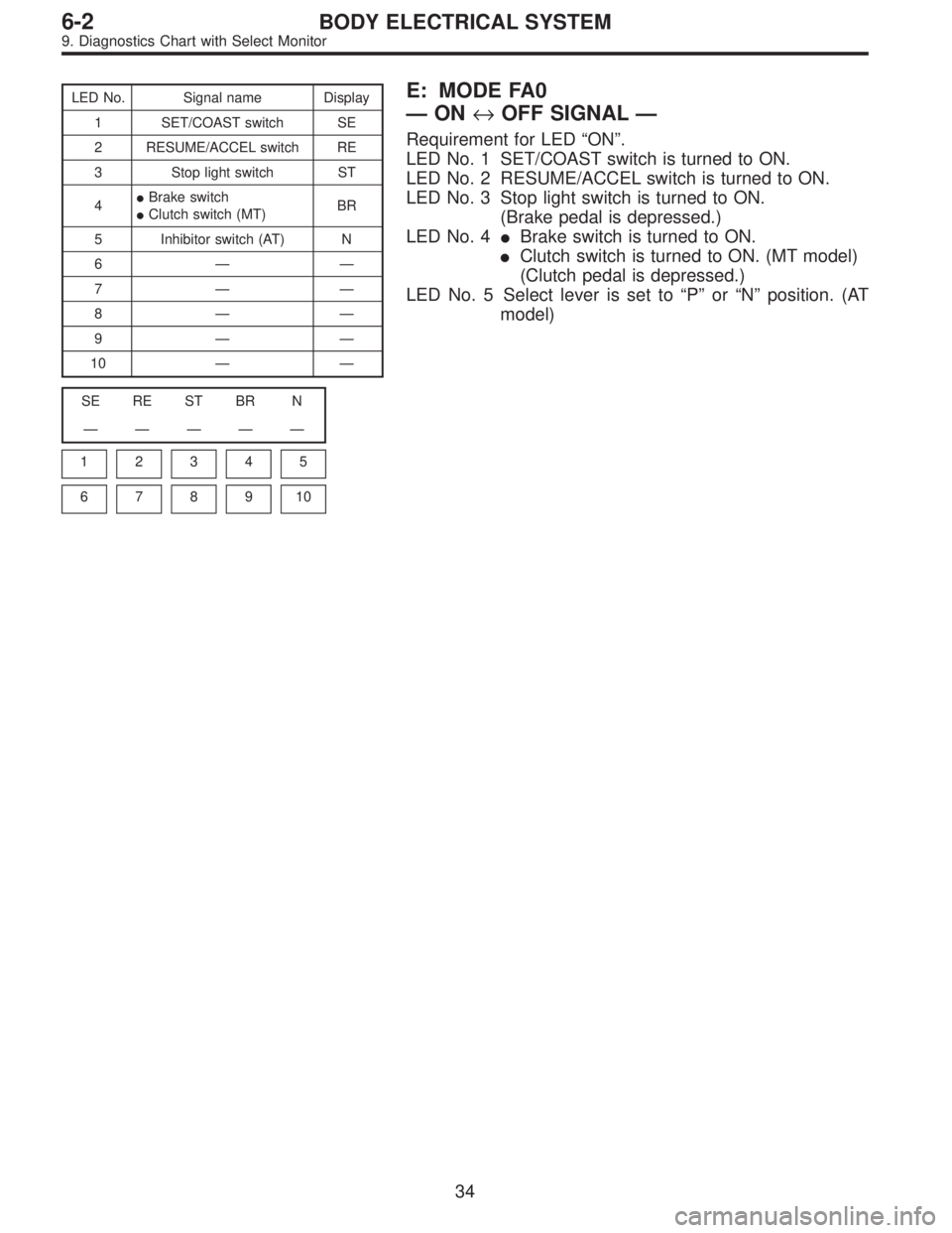
LED No. Signal name Display
1 SET/COAST switch SE
2 RESUME/ACCEL switch RE
3 Stop light switch ST
4�Brake switch
�Clutch switch (MT)BR
5 Inhibitor switch (AT) N
6——
7——
8——
9——
10——
SE RE ST BR N
—————
1
2345
678910
E: MODE FA0
—ON↔OFF SIGNAL—
Requirement for LED“ON”.
LED No. 1 SET/COAST switch is turned to ON.
LED No. 2 RESUME/ACCEL switch is turned to ON.
LED No. 3 Stop light switch is turned to ON.
(Brake pedal is depressed.)
LED No. 4�Brake switch is turned to ON.
�Clutch switch is turned to ON. (MT model)
(Clutch pedal is depressed.)
LED No. 5 Select lever is set to“P”or“N”position. (AT
model)
34
6-2BODY ELECTRICAL SYSTEM
9. Diagnostics Chart with Select Monitor
Page 3341 of 3342
![SUBARU LEGACY 1997 Service Repair Manual G3M0151
3) Turn ignition switch and select monitor switch ON.
4) After display is shown, press slash“/”key.
5) After AT mode is displayed, press function“[0]”.
(Display returns to AT mode when](/manual-img/17/57434/w960_57434-3340.png "SUBARU LEGACY 1997 Service Repair Manual G3M0151
3) Turn ignition switch and select monitor switch ON.
4) After display is shown, press slash“/”key.
5) After AT mode is displayed, press function“[0]”.
(Display returns to AT mode when")
G3M0151
3) Turn ignition switch and select monitor switch ON.
4) After display is shown, press slash“/”key.
5) After AT mode is displayed, press function“[0]”.
(Display returns to AT mode when slash“/”is pressed during
on-board diagnostic operation.)
G3M0152
4. READ TROUBLE CODE SHOWN ON DISPLAY.
1) Connect select monitor.
2) Designate mode using function key.
Press [F] [B] [0] [ENT] in that order.
3) Ensure trouble code(s) is shown.
G3M0152
5. PREVIOUS TROUBLE CODE READING
1) Connect select monitor.
2) Designate mode using function key.
Press [F] [B] [1] [ENT] in that order.
3) Ensure displayed trouble code(s).
C: USING AN OSCILLOSCOPE
A malfunction can be determined by displaying the waveforms
of input/output signals on the oscilloscope.
1. DIAGNOSIS
A simple comparison of the waveforms may lead to an incor-
rect diagnosis. To exactly determine the sources of the mal-
function it will be necessary to determine them under consid-
eration about information other than waveforms.
2. APPLYING INPUT/OUTPUT SIGNALS
Connect the probe directly with the terminal of the signal.
11
[T4C2] FOREWORDFOREWORD
4. Diagnosis and Checking Procedure Using Instruments
—
CONDITION:
Driving at minimum of 40 km/h (25 MPH) and set cruise
control.
SPECIFIED DATA:
Compare displayed vehicle speed on select m")