Page 2954 of 3342

Function code
Measuring items Cont")
G2M0096
9. Select Monitor Function Mode
Applicable cartridge of select monitor: No. 498346300
A: LIST OF FUNCTION MODE
1. F MODE (ROM ID, ANALOG DATA ARE
DISPLAYED.)
Function code
Measuring items Contents to be monitored Scroll Ref. to
Code Abbreviation
F00 ROM ID ECM identificationROM ID number of ECM is read and enabled com-
munication state is displayed.Possible 4-4d [T9B0]
F01 FRFR wheel speed
(mile/h)Wheel speed detected by the FR ABS sensor is
displayed in mile/h.Possible 4-4d [T9C0]
F02 FLFL wheel speed
(mile/h)Wheel speed detected by the FL ABS sensor is dis-
played in mile/h.Possible 4-4d [T9D0]
F03 RRRR wheel speed
(mile/h)Wheel speed detected by the RR ABS sensor is
displayed in mile/h.Possible 4-4d [T9E0]
F04 RLRL wheel speed
(mile/h)Wheel speed detected by the RL ABS sensor is
displayed in mile/h.Possible 4-4d [T9F0]
F05 FRFR wheel speed
(km/h)Wheel speed detected by the FR ABS sensor is
displayed in km/h.Possible 4-4d [T9C0]
F06 FLFL wheel speed
(km/h)Wheel speed detected by the FL ABS sensor is dis-
played in km/h.Possible 4-4d [T9D0]
F07 RRRR wheel speed
(km/h)Wheel speed detected by the RR ABS sensor is
displayed in km/h.Possible 4-4d [T9E0]
F08 RLRL wheel speed
(km/h)Wheel speed detected by the RL ABS sensor is
displayed in km/h.Possible 4-4d [T9F0]
F09 BLSStop light switch
monitorStop light switch monitor voltage is displayed. Possible 4-4d [T9G0]
F10 G-SENSG sensor output volt-
age (V)Refers to vehicle acceleration detecting by the ana-
log G sensor. It appears on the select monitor dis-
play in volts.Possible 4-4d [T9H0]
78
4-4dBRAKES [ABS 5.3i TYPE]
9. Select Monitor Function Mode
Page 2955 of 3342

Function code
Measuring items Contents to be monitored Scroll Ref. to
Code Abbreviation
FA 0B1 Stop light switchLED 1 comes on with the switch on (with the brak")
2. FA MODE (ON/OFF DATA ARE DISPLAYED.)
Function code
Measuring items Contents to be monitored Scroll Ref. to
Code Abbreviation
FA 0B1 Stop light switchLED 1 comes on with the switch on (with the brake
pedal down).
Possible 4-4d [T9I0] VR Valve relay signal LED 2 comes on with the valve relay off.
MR Motor relay signal LED 3 comes on with the motor on.
AT AT ABS signal LED 4 comes on when ABS control is on.
AW ABS warning light LED 6 comes on when the warning light is on.
VM Valve relay monitor LED 1 comes on with the valve relay off.
MM Motor relay monitor LED 8 comes on when the motor relay is on.
CM CCM signal LED 9 comes on when ABS control is on.
3. FB MODE (TROUBLE CODES ARE DISPLAYED.)
Function code
Measuring items Contents to be monitored Scroll Ref. to
Code Abbreviation
FB1D⋅ALL
History of trouble
codes is displayed.A maximum of 3 trouble codes are displayed in
order of occurrence.
Possible 4-4d [T10B0] D⋅NEWThe most recent trouble code appears on the select
monitor display.
D⋅MIDThe second most recent trouble code appears on
the select monitor display.
D⋅OLDThe third most recent trouble code appears on the
select monitor display.
D⋅REFA specified period of time proceeding trouble code
appears on the select monitor display.
B4M0919
NOTE:
�If a particular trouble code is not properly stored in
memory (due to a drop in ABSCM&H/U power supply, etc.)
when a problem occurs, the trouble code, followed by a
question mark“?”, appears on the select monitor display.
This shows it may be an unreliable reading.
�arefers to the troubles in order of occurrence (NEW.
MID, OLD and REF).
79
4-4dBRAKES [ABS 5.3i TYPE]
9. Select Monitor Function Mode
Page 2956 of 3342

Function code
Measuring items Contents to be monitored Scroll Ref. to
Code Abbreviation
FC0 D⋅CLRHistory of trouble
codes is erased.Function of clearing troubl")
4. FC MODE (TROUBLE CODES ARE ERASED.)
Function code
Measuring items Contents to be monitored Scroll Ref. to
Code Abbreviation
FC0 D⋅CLRHistory of trouble
codes is erased.Function of clearing trouble code. Possible 4-4d [T9J0]
5. FD MODE (ABS SEQUENCE CONTROL MODE)
Function code
Measuring items Contents to be monitored Scroll Ref. to
Code Abbreviation
FD1 A⋅CHKABS sequence con-
trolPerform ABS sequence control by operating valve
and pump motor sequentially.Impossible4-4
[W20D2]
6. FE MODE (FREEZE FRAME DATA)
NOTE:
�Data stored at the time of trouble occurrence is shown
on display.
�Each time trouble occurs, the latest information is stored
in the freeze frame data in memory.
Function code
Measuring items Contents to be monitored Scroll Ref. to
Code Abbreviation
FE1 FRFR wheel speed
(mile/h)Wheel speed detected by the FR ABS sensor is
displayed in mile/h.Possible 4-4d [T9K0]
FE2 FLFL wheel speed
(mile/h)Wheel speed detected by the FL ABS sensor is dis-
played in mile/h.Possible 4-4d [T9L0]
FE3 RRRR wheel speed
(mile/h)Wheel speed detected by the RR ABS sensor is
displayed in mile/h.Possible 4-4d [T9M0]
FE4 RLRL wheel speed
(mile/h)Wheel speed detected by the RL ABS sensor is
displayed in mile/h.Possible 4-4d [T9N0]
FE5 FRFR wheel speed
(km/h)Wheel speed detected by the FR ABS sensor is
displayed in km/h.Possible 4-4d [T9K0]
FE6 FLFL wheel speed
(km/h)Wheel speed detected by the FL ABS sensor is dis-
played in km/h.Possible 4-4d [T9L0]
FE7 RRRR wheel speed
(km/h)Wheel speed detected by the RR ABS sensor is
displayed in km/h.Possible 4-4d [T9M0]
FE8 RLRL wheel speed
(km/h)Wheel speed detected by the RL ABS sensor is
displayed in km/h.Possible 4-4d [T9N0]
FE13 POWERABSCM&H/U power
supply voltage (V)Power (in volts) supplied to ABSCM&H/U appears
on the select monitor display.Possible 4-4d [T9O0]
FE14 G-SENSG sensor output volt-
age (V)Refers to vehicle acceleration detected by the ana-
log G sensor. It appears on the select monitor dis-
play in volts.Possible 4-4d [T9P0]
FE15MM Motor relay monitor LED 1 comes on when motor relay is on.
Possible 4-4d [T9Q0] B1 Stop light switchLED 2 comes on with the stop light switch on (with
the brake pedal depressed).
AT AT ABS signal LED 3 comes on when ABS control is on.
CM CCM signal LED 4 comes on when ABS control is on.
A0 ABS control LED 5 comes on when ABS control is on.
FE16 CODE Trouble codeThe most recent trouble code appears on select
monitor display.Possible 4-4d [T9R0]
80
4-4dBRAKES [ABS 5.3i TYPE]
9. Select Monitor Function Mode
Page 2957 of 3342
1) When a trouble code is not stored in memory, activat-
ing the FE mode causes the initial value to appear on the
select monitor display.
�FE1—4: 159 mile/h
�FE5—8: 255 km/h
�FE13: 18.05 V
�FE14: 5.00 V
�FE15: The MM, B1 and A0 LEDs are on.
The AT and CM LEDs are out.
�FE16: NO HISTORY OF OCCURRED
B4M1056
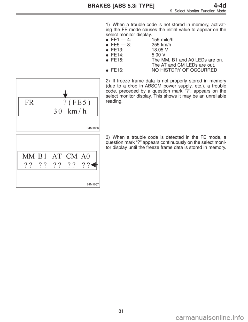
2) If freeze frame data is not properly stored in memory
(due to a drop in ABSCM power supply, etc.), a trouble
code, preceded by a question mark“?”, appears on the
select monitor display. This shows it may be an unreliable
reading.
B4M1057
3) When a trouble code is detected in the FE mode, a
question mark“?”appears continuously on the select moni-
tor display until the freeze frame data is stored in memory.
81
4-4dBRAKES [ABS 5.3i TYPE]
9. Select Monitor Function Mode
Page 2958 of 3342
H4M1117
B: MODE F00
—ROM ID NUMBER (ROM)—
CONDITION:
Ignition switch ON
SPECIFIED DATA:
Presentation display
9B1
CHECK MESSAGE OF DISPLAY.
: Does display indicate message“Error 1”?
: Repair loose or disconnect connector, or discon-
tinued circuit in data link circuit.
: Go to step9B2.
9B2
CHECK MESSAGE OF DISPLAY.
: Does display indicate message“Error 2”?
: Repair poor contact of select monitor cartridge, or
installation of different type select monitor car-
tridge.
: Data link system is normal.
B4M0922
C: MODE F01 AND F05
—FRONT RIGHT WHEEL SPEED SIGNAL
(FR)—
�Compare speedometer with monitor indications.
�F01: FR wheel speed is indicated in mile per hour (mile/
h).
�F05: FR wheel speed is indicated in kilometer per hour
(km/h).
NOTE:
The monitor as shown, indicates that FR wheel speed is 30
km/h.
82
4-4dBRAKES [ABS 5.3i TYPE]
9. Select Monitor Function Mode
Page 2960 of 3342
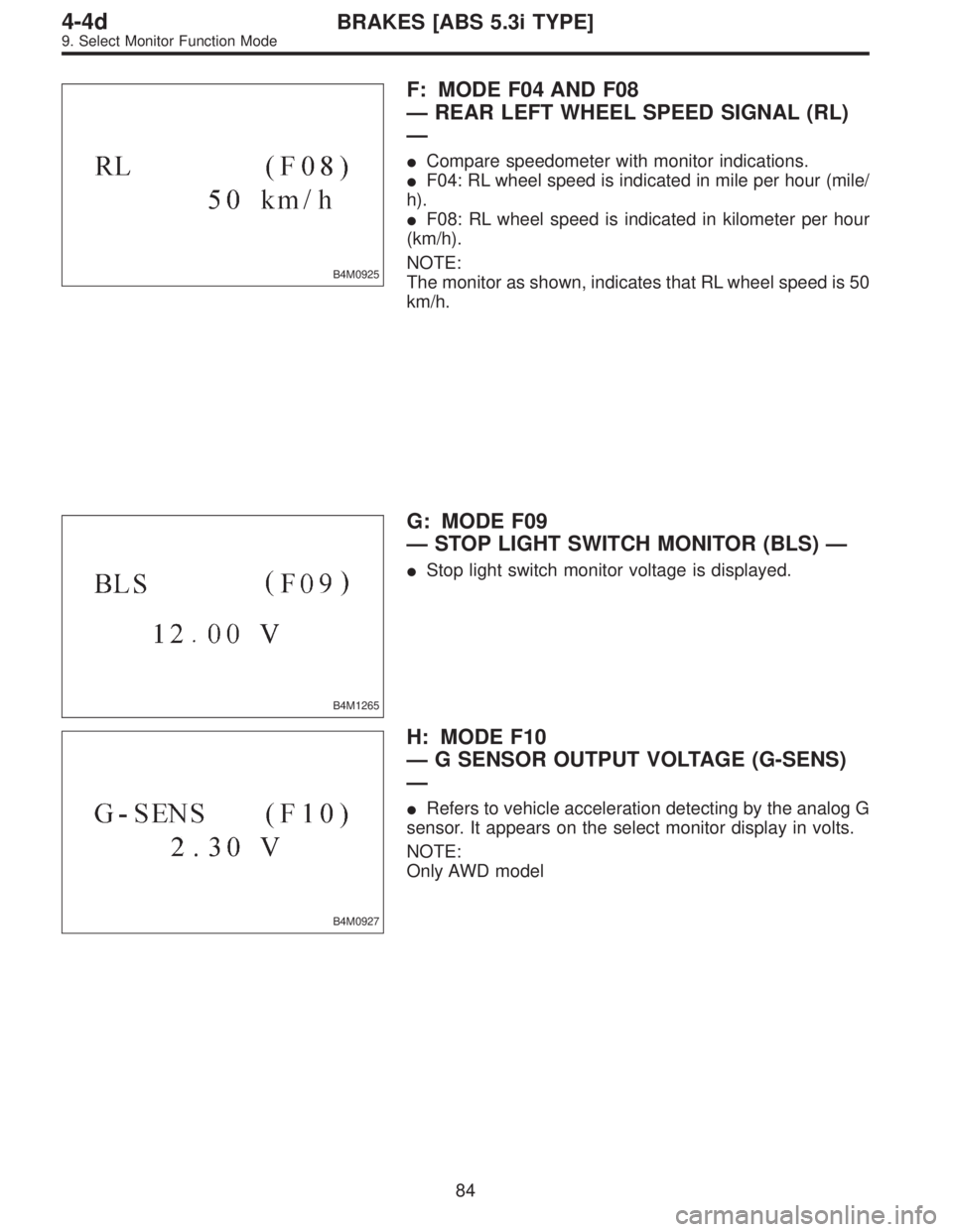
B4M0925
F: MODE F04 AND F08
—REAR LEFT WHEEL SPEED SIGNAL (RL)
—
�Compare speedometer with monitor indications.
�F04: RL wheel speed is indicated in mile per hour (mile/
h).
�F08: RL wheel speed is indicated in kilometer per hour
(km/h).
NOTE:
The monitor as shown, indicates that RL wheel speed is 50
km/h.
B4M1265
G: MODE F09
—STOP LIGHT SWITCH MONITOR (BLS)—
�Stop light switch monitor voltage is displayed.
B4M0927
H: MODE F10
—G SENSOR OUTPUT VOLTAGE (G-SENS)
—
�Refers to vehicle acceleration detecting by the analog G
sensor. It appears on the select monitor display in volts.
NOTE:
Only AWD model
84
4-4dBRAKES [ABS 5.3i TYPE]
9. Select Monitor Function Mode
Page 2961 of 3342
LED No. Signal name Display
1 Stop light switch B1
2 Valve relay signal VR
3 Motor relay signal MR
4 AT ABS signal AT
5——
6 ABS warning light AW
7 Valve relay monitor VM
8 Motor relay monitor MM
9 CCM signal CM
10——
B1 VR MR AT—
AW VM MM CM—
1
2345
678910
I: MODE FA0
—ON↔OFF SIGNAL—
Requirement for LED“ON”
LED No. 1 Stop light switch is turned ON. (With brake
pedal depressed.)
LED No. 2 Valve relay is turned OFF.
LED No. 3 Motor relay is turned ON.
LED No. 4 ABS control operates.
LED No. 6 ABS warning light is ON.
LED No. 7 Valve relay is turned OFF.
LED No. 8 Motor relay is turned ON.
LED No. 9 ABS control operates.
85
4-4dBRAKES [ABS 5.3i TYPE]
9. Select Monitor Function Mode
Page 2965 of 3342
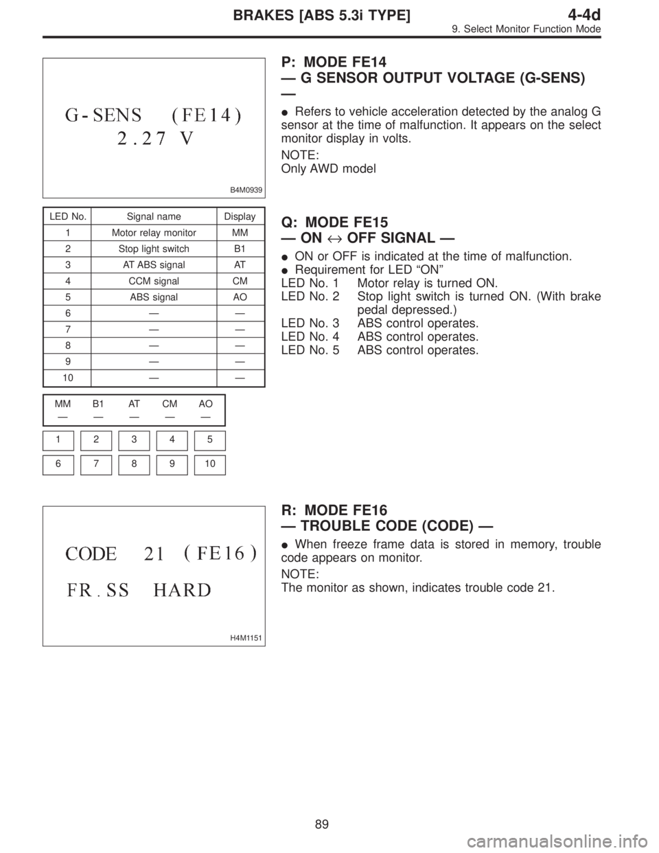
B4M0939
P: MODE FE14
—G SENSOR OUTPUT VOLTAGE (G-SENS)
—
�Refers to vehicle acceleration detected by the analog G
sensor at the time of malfunction. It appears on the select
monitor display in volts.
NOTE:
Only AWD model
LED No. Signal name Display
1 Motor relay monitor MM
2 Stop light switch B1
3 AT ABS signal AT
4 CCM signal CM
5 ABS signal AO
6——
7——
8——
9——
10——
MM B1 AT CM AO
—————
1
2345
678910
Q: MODE FE15
—ON↔OFF SIGNAL—
�ON or OFF is indicated at the time of malfunction.
�Requirement for LED“ON”
LED No. 1 Motor relay is turned ON.
LED No. 2 Stop light switch is turned ON. (With brake
pedal depressed.)
LED No. 3 ABS control operates.
LED No. 4 ABS control operates.
LED No. 5 ABS control operates.
H4M1151
R: MODE FE16
—TROUBLE CODE (CODE)—
�When freeze frame data is stored in memory, trouble
code appears on monitor.
NOTE:
The monitor as shown, indicates trouble code 21.
89
4-4dBRAKES [ABS 5.3i TYPE]
9. Select Monitor Function Mode
—
CONDITION:
Ignition switch ON
SPECIFIED DATA:
Presentation display
9B1
CHECK MESSAGE OF DISPLAY.
: Does display indicate message“Error 1”?
: Repair lo")