Page 2967 of 3342
![SUBARU LEGACY 1997 Service Repair Manual B: LIST OF TROUBLE CODE
Code Display screen (FB1) Contents of diagnosis Ref. to
—ERROR 3 (1) Select monitor communication failure 4-4d [T10C0]
11 NO TROUBLEAlthough no trouble appears on the select](/manual-img/17/57434/w960_57434-2966.png "SUBARU LEGACY 1997 Service Repair Manual B: LIST OF TROUBLE CODE
Code Display screen (FB1) Contents of diagnosis Ref. to
—ERROR 3 (1) Select monitor communication failure 4-4d [T10C0]
11 NO TROUBLEAlthough no trouble appears on the select")
B: LIST OF TROUBLE CODE
Code Display screen (FB1) Contents of diagnosis Ref. to
—ERROR 3 (1) Select monitor communication failure 4-4d [T10C0]
11 NO TROUBLEAlthough no trouble appears on the select monitor display, the ABS
warning light remains on.4-4d [T10D0]
21 FR. SS HARD Open circuit or input voltage too high of FR sensor 4-4d [T10E0]
22 FR. SS SOFT Abnormal ABS sensor signal of FR sensor 4-4d [T10I0]
23 FL. SS HARD Open circuit or input voltage too high of FL sensor 4-4d [T10F0]
24 FL. SS SOFT Abnormal ABS sensor signal of FL sensor 4-4d [T10J0]
25 RR. SS HARD Open circuit or input voltage too high of RR sensor 4-4d [T10G0]
26 RR. SS SOFT Abnormal ABS sensor signal of RR sensor 4-4d [T10K0]
27 RL. SS HARD Open circuit or input voltage too high of RL sensor 4-4d [T10H0]
28 RL. SS SOFT Abnormal ABS sensor signal of RL sensor 4-4d [T10L0]
29 EITHER. SS SOFT Abnormal ABS sensor signal (any one of four) 4-4d [T10M0]
31 FR. EV VALVE Abnormal FR inlet valve 4-4d [T10N0]
32 FR. AV VALVE Abnormal FR outlet valve 4-4d [T10R0]
33 FL. EV VALVE Abnormal FL inlet valve 4-4d [T10O0]
34 FL. AV VALVE Abnormal FL outlet valve 4-4d [T10S0]
35 RR. EV VALVE Abnormal RR inlet valve 4-4d [T10P0]
36 RR. AV VALVE Abnormal RR outlet valve 4-4d [T10T0]
37 RL. EV VALVE Abnormal RL inlet valve 4-4d [T10Q0]
38 RL. AV VALVE Abnormal RL outlet valve 4-4d [T10U0]
41 ECU Abnormal ABSCM&H/U 4-4d [T10V0]
42LOW VOLTAGE Source voltage is low. 4-4d [T10W0]
HIGH VOLTAGE Source voltage is high. 4-4d [T10X0]
44CCM LINE A combination of AT control abnormals (ABS not in control) 4-4d [T10Y0]
CCM OPEN A combination of AT control abnormals (ABS in control) 4-4d [T10Z0]
51V. RELAY Abnormal valve relay 4-4d [T10AA0]
V. RELAY ON Valve relay ON failure 4-4d [T10AB0]
52M. RELAY OPEN Open circuit of motor relay 4-4d [T10AC0]
M. RELAY ON Motor relay ON failure 4-4d [T10AD0]
MOTOR Abnormal motor 4-4d [T10AE0]
54 BLS Abnormal stop light switch 4-4d [T10AF0]
56G SENSOR LINE Open or short circuit of G sensor 4-4d [T10AG0]
G SENSOR +B Battery short of G sensor 4-4d [T10AH0]
G SENSOR H µ Abnormal G sensor high µ output 4-4d [T10AI0]
G SENSOR STICK G sensor output is stuck. 4-4d [T10AJ0]
NOTE:
High µ means high friction coefficient against road sur-
face.
91
4-4dBRAKES [ABS 5.3i TYPE]
10. Diagnostics Chart with Select Monitor
Page 2968 of 3342
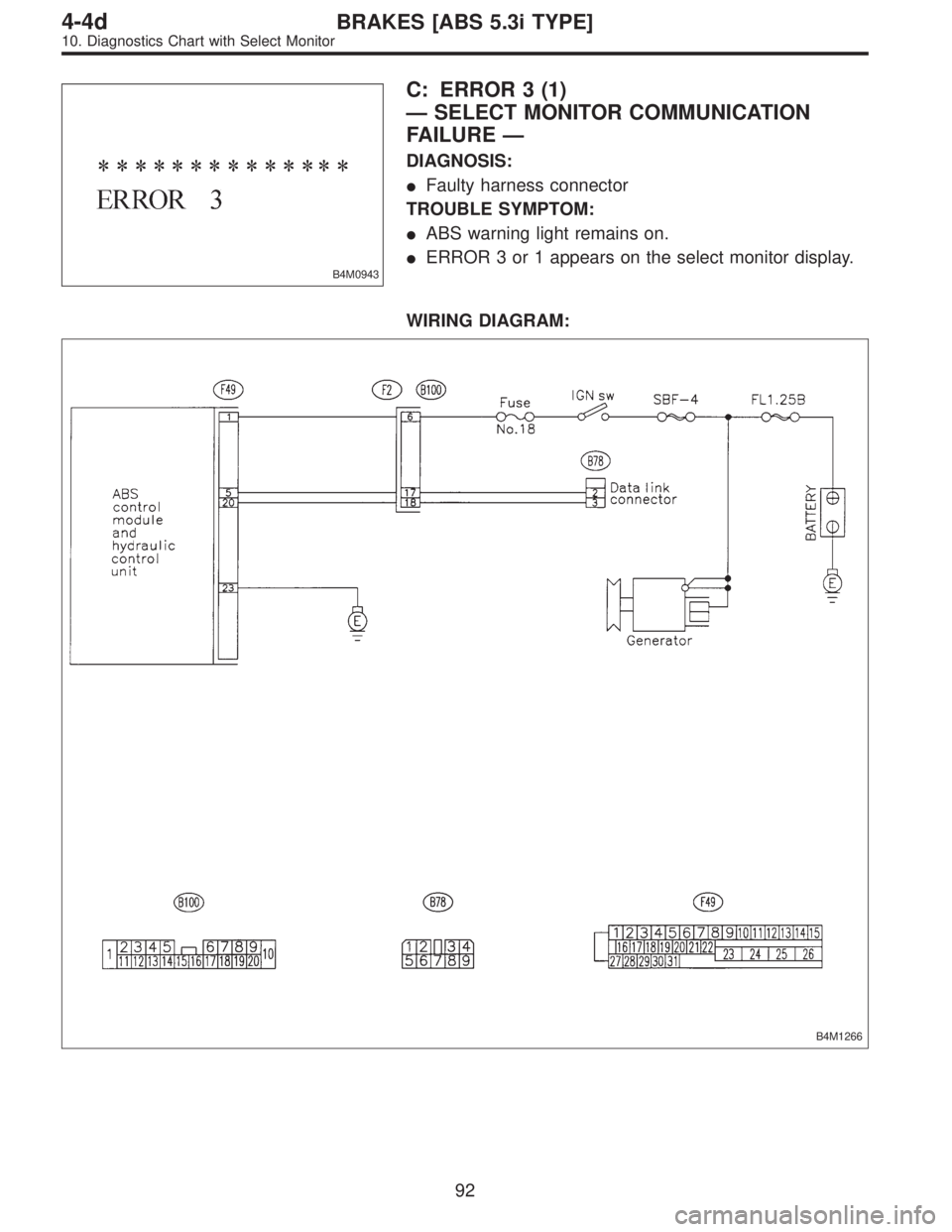
B4M0943
C: ERROR 3 (1)
—SELECT MONITOR COMMUNICATION
FAILURE—
DIAGNOSIS:
�Faulty harness connector
TROUBLE SYMPTOM:
�ABS warning light remains on.
�ERROR 3 or 1 appears on the select monitor display.
WIRING DIAGRAM:
B4M1266
92
4-4dBRAKES [ABS 5.3i TYPE]
10. Diagnostics Chart with Select Monitor
Page 2972 of 3342
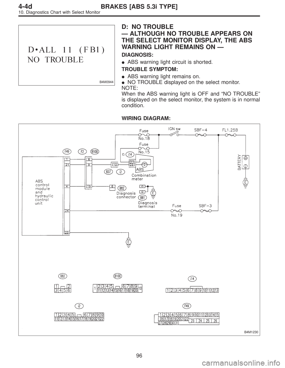
B4M0944
D: NO TROUBLE
—ALTHOUGH NO TROUBLE APPEARS ON
THE SELECT MONITOR DISPLAY, THE ABS
WARNING LIGHT REMAINS ON—
DIAGNOSIS:
�ABS warning light circuit is shorted.
TROUBLE SYMPTOM:
�ABS warning light remains on.
�NO TROUBLE displayed on the select monitor.
NOTE:
When the ABS warning light is OFF and“NO TROUBLE”
is displayed on the select monitor, the system is in normal
condition.
WIRING DIAGRAM:
B4M1230
96
4-4dBRAKES [ABS 5.3i TYPE]
10. Diagnostics Chart with Select Monitor
Page 2977 of 3342

B4M0922
10H1CHECK OUTPUT OF ABS SENSOR
USING SELECT MONITOR.
Read the ABS sensor output corresponding to the faulty
system in the select monitor function mode.
NOTE:
The select monitor display shows that the front right wheel
is rotating at 30 km/h.
: Does the speed indicated on the display
change in response to the speedometer
reading during acceleration/deceleration
when the steering wheel is in the straight-
ahead position?
: Go to step10H2.
: Go to step10H9.
10H2CHECK INSTALLATION OF ABS SEN-
SOR.
Tightening torque:
32±10 N⋅m (3.3±1.0 kg-m, 24±7 ft-lb)
: Are the ABS sensor installation bolts tight-
ened securely?
: Go to step10H3.
: Tighten ABS sensor installation bolts securely.
10H3CHECK INSTALLATION OF TONE
WHEEL.
Tightening torque:
13±3 N⋅m (1.3±0.3 kg-m, 9±2.2 ft-lb)
: Are the tone wheel installation bolts tight-
ened securely?
: Go to step10H4.
: Tighten tone wheel installation bolts securely.
101
4-4dBRAKES [ABS 5.3i TYPE]
10. Diagnostics Chart with Select Monitor
Page 2987 of 3342

B4M0922
10L1CHECK OUTPUT OF ABS SENSOR
USING SELECT MONITOR.
Read the ABS sensor output corresponding to the faulty
system in the select monitor function mode.
NOTE:
The select monitor display shows that the front right wheel
is rotating at 30 km/h.
: Does the speed indicated on the display
change in response to the speedometer
reading during acceleration/deceleration
when the steering wheel is in the straight-
ahead position?
: Go to step10L2.
: Go to step10L8.
10L2CHECK POOR CONTACT IN CONNEC-
TORS.
Turn ignition switch to OFF.
: Is there poor contact in connectors between
ABSCM&H/U and ABS sensor?
: Repair connector.
: Go to step10L3.
10L3
CHECK SOURCES OF SIGNAL NOISE.
: Is the car telephone or the wireless trans-
mitter properly installed?
: Go to step10L4.
: Properly install the car telephone or the wireless
transmitter.
10L4
CHECK SOURCES OF SIGNAL NOISE.
: Are noise sources (such as an antenna)
installed near the sensor harness?
: Install the noise sources apart from the sensor
harness.
: Go to step10L5.
111
4-4dBRAKES [ABS 5.3i TYPE]
10. Diagnostics Chart with Select Monitor
Page 3018 of 3342
![SUBARU LEGACY 1997 Service Repair Manual H4M1117
10Y1CHECK SPECIFICATIONS OF
ABSCM&H/U USING SELECT MONITOR.
1) Press [F], [0] and [0] on the select monitor.
2) Read the select monitor display.
: Is an ABSCM&H/U for AT model installed on
a M](/manual-img/17/57434/w960_57434-3017.png "SUBARU LEGACY 1997 Service Repair Manual H4M1117
10Y1CHECK SPECIFICATIONS OF
ABSCM&H/U USING SELECT MONITOR.
1) Press [F], [0] and [0] on the select monitor.
2) Read the select monitor display.
: Is an ABSCM&H/U for AT model installed on
a M")
H4M1117
10Y1CHECK SPECIFICATIONS OF
ABSCM&H/U USING SELECT MONITOR.
1) Press [F], [0] and [0] on the select monitor.
2) Read the select monitor display.
: Is an ABSCM&H/U for AT model installed on
a MT model?
: Replace ABSCM&H/U.
: Go to step10Y2.
B4M1249A
10Y2
CHECK GROUND SHORT OF HARNESS.
1) Turn ignition switch to OFF.
2) Disconnect two connectors from TCM.
3) Disconnect connector from ABSCM&H/U.
4) Measure resistance between ABSCM&H/U connector
and chassis ground.
Connector & terminal
(F49) No. 3—Chassis ground:
: Is the resistance more than 1 MΩ?
: Go to step10Y3.
: Repair harness between TCM and ABSCM&H/U.
B4M1251A
10Y3
CHECK TCM.
1) Connect all connectors to TCM.
2) Turn ignition switch to ON.
3) Measure voltage between TCM connector terminal and
chassis ground.
Connector & terminal
(B55) No. 5 (+)—Chassis ground (�):
: Is the voltage between 10 V and 15 V?
: Go to step10Y5.
: Go to step10Y4.
142
4-4dBRAKES [ABS 5.3i TYPE]
10. Diagnostics Chart with Select Monitor
Page 3038 of 3342
B4M0973
10AF1CHECK OUTPUT OF STOP LIGHT
SWITCH USING SELECT MONITOR.
1) Press [F], [0] and [9] on the select monitor.
2) Depress the brake pedal.
3) Read the stop light switch output on the select monitor
display.
: Is the reading indicated on monitor display
less than 1.5 V?
: Go to step10AF2.
: Go to step10AF3.
B4M1265
10AF2CHECK OUTPUT OF STOP LIGHT
SWITCH USING SELECT MONITOR.
1) Release the brake pedal.
2) Read the stop light switch output on the select monitor
display.
: Is the reading indicated on monitor display
between 10 V and 15 V?
: Go to step10AF5.
: Go to step10AF3.
10AF3
CHECK IF STOP LIGHTS COME ON.
Depress the brake pedal.
: Do stop lights turn on?
: Go to step10AF4.
: Repair stop lights circuit.
162
4-4dBRAKES [ABS 5.3i TYPE]
10. Diagnostics Chart with Select Monitor
Page 3041 of 3342
![SUBARU LEGACY 1997 Service Repair Manual H4M1117
10AG1CHECK SPECIFICATIONS OF
ABSCM&H/U USING SELECT MONITOR.
1) Press [F], [0] and [0] on the select monitor.
2) Read the select monitor display.
: Is an ABSCM&H/U for 4WD model installed
on a](/manual-img/17/57434/w960_57434-3040.png "SUBARU LEGACY 1997 Service Repair Manual H4M1117
10AG1CHECK SPECIFICATIONS OF
ABSCM&H/U USING SELECT MONITOR.
1) Press [F], [0] and [0] on the select monitor.
2) Read the select monitor display.
: Is an ABSCM&H/U for 4WD model installed
on a")
H4M1117
10AG1CHECK SPECIFICATIONS OF
ABSCM&H/U USING SELECT MONITOR.
1) Press [F], [0] and [0] on the select monitor.
2) Read the select monitor display.
: Is an ABSCM&H/U for 4WD model installed
on a FWD model?
: Replace ABSCM&H/U.
: Go to step10AG2.
B4M0927
10AG2CHECK OUTPUT OF G SENSOR USING
SELECT MONITOR.
1) Press [F], [1] and [0] on the select monitor.
2) Read the select monitor display.
: Is the indicated reading between 2.1 and 2.5
V when the G sensor is in horizontal posi-
tion?
: Go to step10AG3.
: Go to step10AG6.
10AG3CHECK POOR CONTACT IN CONNEC-
TORS.
: Is there poor contact in connector between
ABSCM&H/U and G sensor?
WORD [T3C1].>
: Repair connector.
: Go to step10AG4.
10AG4
CHECK ABSCM&H/U.
1) Connect all connectors.
2) Erase the memory.
3) Perform inspection mode.
4) Read out the trouble code.
: Is the same trouble code as in the current
diagnosis still being output?
: Replace ABSCM&H/U.
: Go to step10AG5.
10AG5CHECK ANY OTHER TROUBLE CODES
APPEARANCE.
: Are other trouble codes being output?
: Proceed with the diagnosis corresponding to the
trouble code.
: A temporary poor contact.
165
4-4dBRAKES [ABS 5.3i TYPE]
10. Diagnostics Chart with Select Monitor
![SUBARU LEGACY 1997 Service Repair Manual B4M0973
10AF1CHECK OUTPUT OF STOP LIGHT
SWITCH USING SELECT MONITOR.
1) Press [F], [0] and [9] on the select monitor.
2) Depress the brake pedal.
3) Read the stop light switch output on the select mon](/manual-img/17/57434/w960_57434-3037.png "SUBARU LEGACY 1997 Service Repair Manual B4M0973
10AF1CHECK OUTPUT OF STOP LIGHT
SWITCH USING SELECT MONITOR.
1) Press [F], [0] and [9] on the select monitor.
2) Depress the brake pedal.
3) Read the stop light switch output on the select mon")