Page 3042 of 3342
![SUBARU LEGACY 1997 Service Repair Manual B4M0977
10AG6
CHECK FREEZE FRAME DATA.
1) Press [F], [E] and [5] on the select monitor.
2) Read the select monitor display.
: Is the reading indicated on monitor display
0 km?
: Go to step10AG7.
: Go](/manual-img/17/57434/w960_57434-3041.png "SUBARU LEGACY 1997 Service Repair Manual B4M0977
10AG6
CHECK FREEZE FRAME DATA.
1) Press [F], [E] and [5] on the select monitor.
2) Read the select monitor display.
: Is the reading indicated on monitor display
0 km?
: Go to step10AG7.
: Go")
B4M0977
10AG6
CHECK FREEZE FRAME DATA.
1) Press [F], [E] and [5] on the select monitor.
2) Read the select monitor display.
: Is the reading indicated on monitor display
0 km?
: Go to step10AG7.
: Go to step10AG15.
B4M0978
10AG7
CHECK FREEZE FRAME DATA.
1) Press the scroll key so that FE6 appears on the moni-
tor display.
2) Read the select monitor display.
: Is the reading indicated on monitor display
0 km?
: Go to step10AG8.
: Go to step10AG15.
B4M0979
10AG8
CHECK FREEZE FRAME DATA.
1) Press the scroll key so that FE7 appears on the moni-
tor display.
2) Read the select monitor display.
: Is the reading indicated on monitor display
0 km?
: Go to step10AG9.
: Go to step10AG15.
B4M0980
10AG9
CHECK FREEZE FRAME DATA.
1) Press the scroll key so that FE8 appears on the moni-
tor display.
2) Read the select monitor display.
: Is the reading indicated on monitor display
0 km?
: Go to step10AG10.
: Go to step10AG15.
B4M0981
10AG10
CHECK FREEZE FRAME DATA.
1) Press the scroll key so that FE14 appears on the moni-
tor display.
2) Read the select monitor display.
: Is the reading indicated on monitor display
more than 3.65 V?
: Go to step10AG11.
: Go to step10AG15.
166
4-4dBRAKES [ABS 5.3i TYPE]
10. Diagnostics Chart with Select Monitor
Page 3048 of 3342
![SUBARU LEGACY 1997 Service Repair Manual B4M0927
10AH1CHECK OUTPUT OF G SENSOR USING
SELECT MONITOR.
1) Press [F], [1] and [0] on the select monitor.
2) Read the select monitor display.
: Is the indicated reading between 2.1 and 2.5
V when t](/manual-img/17/57434/w960_57434-3047.png "SUBARU LEGACY 1997 Service Repair Manual B4M0927
10AH1CHECK OUTPUT OF G SENSOR USING
SELECT MONITOR.
1) Press [F], [1] and [0] on the select monitor.
2) Read the select monitor display.
: Is the indicated reading between 2.1 and 2.5
V when t")
B4M0927
10AH1CHECK OUTPUT OF G SENSOR USING
SELECT MONITOR.
1) Press [F], [1] and [0] on the select monitor.
2) Read the select monitor display.
: Is the indicated reading between 2.1 and 2.5
V when the G sensor is in horizontal posi-
tion?
: Replace ABSCM&H/U.
: Go to step10AH2.
B4M1263A
10AH2
CHECK BATTERY SHORT OF HARNESS.
1) Turn ignition switch to OFF.
2) Remove console box.
3) Disconnect connector from G sensor.
4) Disconnect connector from ABSCM&H/U.
5) Measure voltage between ABSCM&H/U connector and
chassis ground.
Connector & terminal
(F49) No. 6 (+)—Chassis ground (�):
: Is the voltage less than 1 V?
: Go to step10AH3.
: Repair harness between G sensor and
ABSCM&H/U.
B4M1263A
10AH3
CHECK BATTERY SHORT OF HARNESS.
1) Turn ignition switch to ON.
2) Measure voltage between ABSCM&H/U connector and
chassis ground.
Connector & terminal
(F49) No. 6 (+)—Chassis ground (�):
: Is the voltage less than 1 V?
: Go to step10AH4.
: Repair harness between G sensor and
ABSCM&H/U.
172
4-4dBRAKES [ABS 5.3i TYPE]
10. Diagnostics Chart with Select Monitor
Page 3051 of 3342
B4M0927
10AI1CHECK OUTPUT OF G SENSOR USING
SELECT MONITOR.
1) Press [F], [1] and [0] on the select monitor.
2) Read the select monitor display.
: Is the indicated reading 2.3±0.2 V when the
G sensor is in horizontal position?
: Go to step10AI2.
: Go to step10AI6.
10AI2CHECK POOR CONTACT IN CONNEC-
TORS.
Turn ignition switch to OFF.
: Is there poor contact in connector between
ABSCM&H/U and G sensor?
WORD [T3C1].>
: Repair connector.
: Go to step10AI3.
10AI3
CHECK ABSCM&H/U.
1) Connect all connectors.
2) Erase the memory.
3) Perform inspection mode.
4) Read out the trouble code.
: Is the same trouble code as in the current
diagnosis still being output?
: Replace ABSCM&H/U.
: Go to step10AI4.
10AI4CHECK ANY OTHER TROUBLE CODES
APPEARANCE.
: Are other trouble codes being output?
: Proceed with the diagnosis corresponding to the
trouble code.
: A temporary poor contact.
175
4-4dBRAKES [ABS 5.3i TYPE]
10. Diagnostics Chart with Select Monitor
Page 3056 of 3342

10AJ1CHECK ALL FOUR WHEELS FOR FREE
TURNING.
: Have the wheels been turned freely such as
when the vehicle is lifted up, or operated on
a rolling road?
: The ABS is normal. Erase the trouble code.
: Go to step10AJ2.
B4M0927
10AJ2CHECK OUTPUT OF G SENSOR USING
SELECT MONITOR.
1) Press [F], [1] and [0] on the select monitor.
2) Read the select monitor display.
: Is the indicated reading between 2.1 and 2.5
V when the vehicle is in horizontal position?
: Go to step10AJ3.
: Go to step10AJ8.
B4M0917A
10AJ3CHECK OUTPUT OF G SENSOR USING
SELECT MONITOR.
1) Turn ignition switch to OFF.
2) Remove console box.
3) Remove G sensor from vehicle. (Do not disconnect
connector.)
4) Turn ignition switch to ON.
5) Press [F], [1] and [0] on the select monitor.
6) Read the select monitor display.
: Is the indicated reading between 3.7 and 4.1
V when G sensor is inclined forwards to
90°?
: Go to step10AJ4.
: Replace G sensor.
B4M0918A
10AJ4CHECK OUTPUT OF G SENSOR USING
SELECT MONITOR.
Read the select monitor display.
: Is the indicated reading between 0.5 and 0.9
V when G sensor is inclined backwards to
90°?
: Go to step10AJ5.
: Replace G sensor.
180
4-4dBRAKES [ABS 5.3i TYPE]
10. Diagnostics Chart with Select Monitor
Page 3156 of 3342
 Connect select monitor.
2) Start the engine and turn cruise control main switch to
ON.
3) Set select monitor in“FB0”mode.
4) Drive vehicle at least 40 km/h")
2. CRUISE CANCEL CONDITIONS DIAGNOSIS
1) Connect select monitor.
2) Start the engine and turn cruise control main switch to
ON.
3) Set select monitor in“FB0”mode.
4) Drive vehicle at least 40 km/h (25 MPH) with cruise
speed set.
5) If cruise speed is canceled itself (without doing any
cancel operations), a trouble code will appear on select
monitor display.
CAUTION:
�A trouble code will also appear when cruise cancel
is effected by driver. Do not confuse.
�Have a co-worker ride in vehicle to assist in diagno-
sis during driving.
NOTE:
Trouble code will be cleared by turning ignition switch or
cruise control main switch to OFF.
3. REAL-TIME DIAGNOSIS
1) Connect select monitor.
2) Turn ignition switch and cruise control main switch to
ON.
3) Set select monitor in“FA 0”mode.
4) Ensure that normal indication is displayed when con-
trols are operated as indicated below:
�When SET/COAST switch is pressed.
�When RESUME/ACCEL switch is pressed.
�When brake pedal is depressed. (Stop and brake switch
turns ON.)
�When clutch pedal is depressed. (MT model)
�When select lever is set to N position. (AT model)
10
6-2BODY ELECTRICAL SYSTEM
6. Diagnostics Chart for On-board Diagnosis System
Page 3164 of 3342
BR
5 Inhibitor switch (AT) N
6——
7——
8——
9——
10—�")
LED No. Signal name Display
1 SET/COAST switch SE
2 RESUME/ACCEL switch RE
3 Stop light switch ST
4�Brake switch
�Clutch switch (MT)BR
5 Inhibitor switch (AT) N
6——
7——
8——
9——
10——
SE RE ST BR N
—————
1
2345
678910
1. CHECK THE SIGNAL USING A SELECT MONITOR.
1) Turn ignition switch to ON.
2) Turn cruise control main switch to ON.
3) Set select monitor in“FA 0”mode.
4) Check signals for proper operation.
(1) When pushing the SET switch:
LED No. 1 goes out—lights.
(2) When pushing the RESUME switch:
LED No. 2 goes out—lights.
B6M0533
B6M0527
2. CHECK THE CRUISE CONTROL COMMAND
SWITCH.
1) Disconnect connector from command switch.
2) Measure voltage between connector (S1) and body.
Connector & terminal / Specified voltage:
(S1) No. 1—Body / 10 V, or more
3) Check for harness short circuit between command
switch and body.
Terminals / Specified resistance:
No. 2—Body / 1 MΩ, min.
No. 3—Body / 1 MΩ, min.
B6M0534
4) Measure resistance between each terminal of switch
side connector to check the switch operation.
Terminals:
No. 1—No. 2 (SET/COAST SWITCH)
No. 1—No. 3 (RESUME/ACCEL SWITCH)
Specified resistance:
10Ω, max. (ON)
1MΩ, min. (OFF)
18
6-2BODY ELECTRICAL SYSTEM
8. Diagnostics Chart with Trouble Code
Page 3166 of 3342
BR
5 Inhibitor switch (AT) N
6——
7——
8——
9——
10—�")
LED No. Signal name Display
1 SET/COAST switch SE
2 RESUME/ACCEL switch RE
3 Stop light switch ST
4�Brake switch
�Clutch switch (MT)BR
5 Inhibitor switch (AT) N
6——
7——
8——
9——
10——
SE RE ST BR N
—————
1
2345
678910
1. CHECK THE SIGNAL USING A SELECT MONITOR.
1) Turn ignition switch to ON.
2) Turn cruise control main switch to ON.
3) Apply parking brake securely.
4) Set select monitor in“FA 0”mode.
5) Release the clutch pedal. (MT model)
6) Depress the brake pedal and check signals for proper
operation.
Stop light switch: LED No. 3 goes out—lights.
Brake switch : LED No. 4 goes out—lights.
7) Release the brake pedal.
8) Depress the clutch pedal and check signal for proper
operation. (MT model)
Clutch switch: LED No. 4 goes out—lights.
9) Set the selector lever from D to N position and check
signal for proper operation. (AT model)
Inhibitor switch: LED No. 5 goes out—lights.
G6M0183
2. CHECK BRAKE SWITCH AND STOP LIGHT
SWITCH.
1) Remove connector of stop and brake switch.
2) Check circuit between each terminal.
Pedal operationBrake switch between
No. 1—No. 4Stop light switch between
No. 2—No. 3
Depressing the
brake pedal.1MΩ,ormore 1Ω, or less
Without
depressing the
brake pedal.1Ω, or less 1 MΩ,ormore
G6M0184
3. CHECK CLUTCH SWITCH. (MT MODEL)
1) Disconnect connector from clutch switch.
2) Check continuity of the clutch switch.
Terminals / Specified resistance:
No. 1—No. 2 / 10Ω, max. (Without pedal
depressing.)
/1MΩ, min. (Pedal depressing.)
20
6-2BODY ELECTRICAL SYSTEM
8. Diagnostics Chart with Trouble Code
Page 3178 of 3342
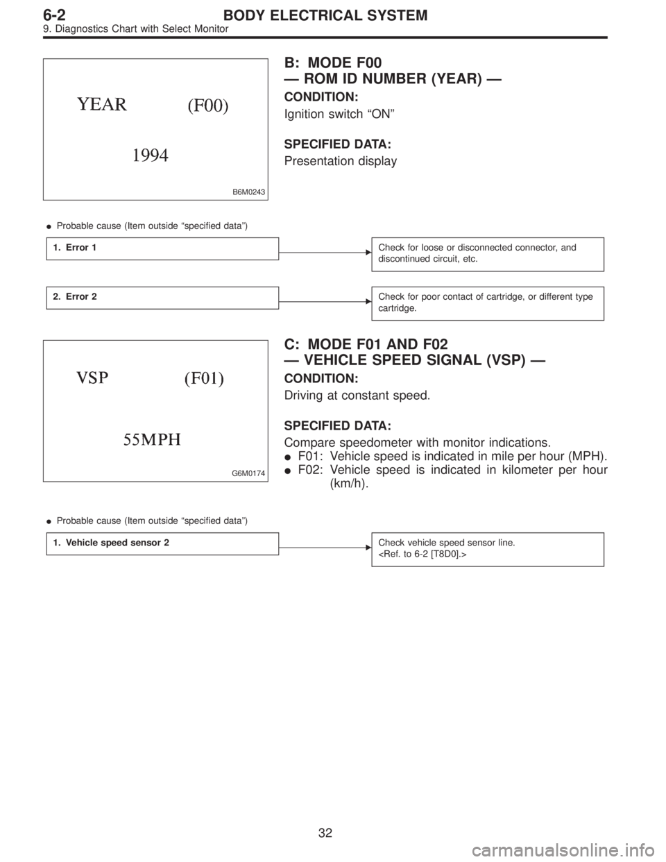
B6M0243
B: MODE F00
—ROM ID NUMBER (YEAR)—
CONDITION:
Ignition switch“ON”
SPECIFIED DATA:
Presentation display
�Probable cause (Item outside“specified data”)
1. Error 1
�Check for loose or disconnected connector, and
discontinued circuit, etc.
2. Error 2�Check for poor contact of cartridge, or different type
cartridge.
G6M0174
C: MODE F01 AND F02
—VEHICLE SPEED SIGNAL (VSP)—
CONDITION:
Driving at constant speed.
SPECIFIED DATA:
Compare speedometer with monitor indications.
�F01: Vehicle speed is indicated in mile per hour (MPH).
�F02: Vehicle speed is indicated in kilometer per hour
(km/h).
�Probable cause (Item outside“specified data”)
1. Vehicle speed sensor 2
�Check vehicle speed sensor line.
32
6-2BODY ELECTRICAL SYSTEM
9. Diagnostics Chart with Select Monitor
![SUBARU LEGACY 1997 Service Repair Manual B4M0927
10AI1CHECK OUTPUT OF G SENSOR USING
SELECT MONITOR.
1) Press [F], [1] and [0] on the select monitor.
2) Read the select monitor display.
: Is the indicated reading 2.3±0.2 V when the
G sensor](/manual-img/17/57434/w960_57434-3050.png "SUBARU LEGACY 1997 Service Repair Manual B4M0927
10AI1CHECK OUTPUT OF G SENSOR USING
SELECT MONITOR.
1) Press [F], [1] and [0] on the select monitor.
2) Read the select monitor display.
: Is the indicated reading 2.3±0.2 V when the
G sensor")