Page 1899 of 3342
B2M0755
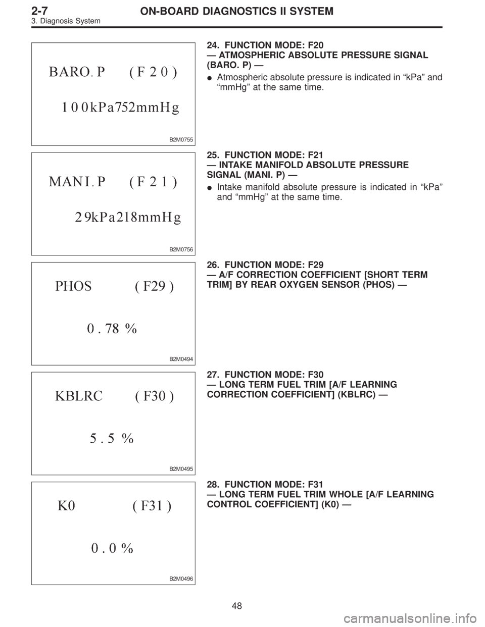
24. FUNCTION MODE: F20
—ATMOSPHERIC ABSOLUTE PRESSURE SIGNAL
(BARO. P)—
�Atmospheric absolute pressure is indicated in“kPa”and
“mmHg”at the same time.
B2M0756
25. FUNCTION MODE: F21
—INTAKE MANIFOLD ABSOLUTE PRESSURE
SIGNAL (MANI. P)—
�Intake manifold absolute pressure is indicated in“kPa”
and“mmHg”at the same time.
B2M0494
26. FUNCTION MODE: F29
—A/F CORRECTION COEFFICIENT [SHORT TERM
TRIM] BY REAR OXYGEN SENSOR (PHOS)—
B2M0495
27. FUNCTION MODE: F30
—LONG TERM FUEL TRIM [A/F LEARNING
CORRECTION COEFFICIENT] (KBLRC)—
B2M0496
28. FUNCTION MODE: F31
—LONG TERM FUEL TRIM WHOLE [A/F LEARNING
CONTROL COEFFICIENT] (K0)—
48
2-7ON-BOARD DIAGNOSTICS II SYSTEM
3. Diagnosis System
Page 1901 of 3342
B2M0501
34. FUNCTION MODE: F38
—MAXIMUM VALUE OF CYLINDER #3 MISFIRE RATE
DURING 100 ROTATIONS (MF3)—
B2M0502
35. FUNCTION MODE: F39
—MAXIMUM VALUE OF CYLINDER #4 MISFIRE RATE
DURING 100 ROTATIONS (MF4)—
B2M0759
36. FUNCTION MODE: F42
—MAXIMUM AND MINIMUM EGR SYSTEM
PRESSURE VALUE [AT VEHICLES] (EGRMAX-MIN)—
�Maximum and minimum EGR system pressure value are
indicated at the same time.
H2M1326
37. FUNCTION MODE: F43
—FUEL TANK PRESSURE SIGNAL (TNKP)—
H2M1308
38. FUNCTION MODE: F44
—FUEL TEMPERATURE SIGNAL (TNKT)—
50
2-7ON-BOARD DIAGNOSTICS II SYSTEM
3. Diagnosis System
Page 1902 of 3342
H2M1327
39. FUNCTION MODE: F45
—FUEL LEVEL SIGNAL (FLEVEL)—
51
2-7ON-BOARD DIAGNOSTICS II SYSTEM
3. Diagnosis System
Page 1903 of 3342

40. FA MODE FOR ENGINE
Function
modeLED No. Contents Display LED“ON”requirements
FA 03 Neutral switch NT When neutral position signal is entered.
7 Test mode connector UD When test mode connector is connected.
8 AT/MT identification signal AT When AT identification signal is entered.
9 Ignition switch IG When ignition switch is turned ON.
FA 11 Radiator fan relay 2 R2 When radiator fan relay 2 is in function.
2 Knock signal KS When knock signal is entered.
3 Purge control solenoid valve CN When purge control solenoid valve is in function.
4 Fuel pump relay FP When fuel pump relay is in function.
6 Radiator fan relay 1 R1 When radiator fan relay 1 is in function.
7 Air conditioner relay AR When air conditioner relay is in function.
8 Air conditioner switch AC When air conditioner switch is turned ON.
FA 22 AEC signal EC When AEC signal is entered.
3 EAM signal AM When EAM signal is gone out.
4 AEB signal EB When AEB signal is entered.
6 AET signal ET When AET signal is entered.
7 Engine torque control signal TR When engine torque control signal is entered.
FA3 7 Pressure sources switching solenoid valve BRWhen pressure sources switching solenoid valve
is in function.
FA 41 Catalyst CA When diagnosis of catalyzer is finished.
2 EGR system E1 When diagnosis of EGR system is finished.
3 California spec. vehicle identification signal FCWhen Federal spec. vehicle identification signal is
entered.
8 Rear oxygen sensor signal OR When rear oxygen sensor mixture ratio is rich.
9 Front oxygen sensor signal O2 When front oxygen sensor mixture ratio is rich.
FA 56 Vent control solenoid valve AL When vent control solenoid valve is in function.
7 EGR solenoid valve ER When EGR solenoid valve is in function.
8 Pressure control solenoid valve PCWhen pressure control solenoid valve is in
function.
52
2-7ON-BOARD DIAGNOSTICS II SYSTEM
3. Diagnosis System
Page 1904 of 3342

LED No. Signal name Display
1——
2——
3 Neutral switch NT
4——
5——
6——
7 Test mode connector UD
8 Identification of AT model AT
9 Ignition switch IG
0——
——NT——
—UD AT IG—
1
2345
67890
41. FUNCTION MODE: FA0
—ON↔OFF SIGNAL—
Requirement for LED“ON”.
LED No. 3�On MT model, gear position is in neutral.
�On AT model, shift position is in“P”or“N”.
LED No. 7 Test mode connector is connected.
LED No. 8 Vehicle is AT model.
LED No. 9 Ignition switch is turned ON.
LED No. Signal name Display
1 Radiator fan relay 2 R2
2 Knock signal KS
3Purge control solenoid
valveCN
4 Fuel pump relay FP
5——
6 Radiator fan relay 1 R1
7 A/C relay AR
8 A/C switch AC
9——
0——
R2 KS CN FP—
R1 AR AC——
1
2345
67890
42. FUNCTION MODE: FA1
—ON↔OFF SIGNAL—
Requirement for LED“ON”.
LED No. 1 Radiator fan relay 2 is turned ON.
LED No. 2 Engine is knocking.
LED No. 3 Purge control solenoid valve is in function.
LED No. 4 Fuel pump relay is turned ON.
LED No. 6 Radiator fan relay 1 is turned ON.
LED No. 7 A/C relay is turned ON.
LED No. 8 A/C switch is turned ON.
NOTE:
�When LED No. 1, 3, 4, 6 and 7 blinks with the test mode
connector connected and the ignition switch turned to ON,
the corresponding part is functioning properly.
�When LED No. 4 illuminates for only 2 seconds after the
ignition switch is turned to ON, (and then goes out), the
corresponding part is functioning properly.
�LED No. 3 is applicable only to the models not equipped
with enhanced evaporative emission control system.
53
2-7ON-BOARD DIAGNOSTICS II SYSTEM
3. Diagnosis System
Page 1907 of 3342
Current trouble code indicated by on-board
diagnostics after clear memo")
47. FB MODE FOR ENGINE
Function mode Abbreviation Contents Contents of display Page
FB0 INSPECT On-board diagnostics (Inspection)Current trouble code indicated by on-board
diagnostics after clear memory.65
FB1 OBD On-board diagnostics (Read data)Current trouble code indicated by on-board
diagnostics.37
FB2LOAD�F Load data
�Freeze frame data
�Data stored at the time of trouble
occurrence, is shown on display.38
TW�F Engine coolant temperature signal
ALPH�F Throttle position signal
KBLR�F Long term fuel trim
MANI�FIntake manifold absolute pressure
signal
EREV�F Engine speed signal
VSP�F Vehicle speed signal
FB3QA�F (P0100) Mass air flow signal
�Freeze frame data
�Data stored at the time of trouble
occurrence, is shown on display.40
PS�F (P0105) Pressure signal
PR�F (P0106) Pressure signal
TW�F (P0115) Engine coolant temperature signal
THV�F (P0120) Throttle position signal
EGR (P0403) EGR control solenoid valve signal
CPC (P0443) Purge control solenoid valve signal
STSW (P1100) Start switch signal
BR1 (P1102)Pressure sources switching sole-
noid valve signal
FAN1 (P1500) Radiator fan relay 1 signal
48. FC MODE FOR ENGINE
Function mode Abbreviation Contents Contents of display Page
FC0 MEMORY CLR Back-up memory clearFunction of clearing trouble code stored in
memory.64
49. FD MODE FOR ENGINE
Function mode Abbreviation Contents Contents of display Page
FD01 FUEL PUMP
Compulsory valve operation checkFunction of checking operation of fuel
pump relay, purge control solenoid valve,
radiator fan relay, A/C relay, EGR control
solenoid valve, pressure control solenoid
valve, vent control solenoid valve and pres-
sure sources switching solenoid valve.71
FD02 CPC SOL
FD03 RAD FAN
FD04 A/C RELAY
FD05 EGR SOL
FD07 PCV SOL
FD08 VENT SOL
FD10 BR SOL
NOTE:
Because ASV solenoid valve, FICD solenoid valve and air
injection system diagnosis solenoid valve are not installed,
FD06, FD09 and FD11 will be displayed but non-functional.
56
2-7ON-BOARD DIAGNOSTICS II SYSTEM
3. Diagnosis System
Page 1927 of 3342
, main relay and fuel pump relay.
CAUTION:
�All Airbag system wirin")
4. Cautions
A: SUPPLEMENTAL RESTRAINT SYSTEM
“AIRBAG”
Airbag system wiring harness is routed near the engine
control module (ECM), main relay and fuel pump relay.
CAUTION:
�All Airbag system wiring harness and connectors
are colored yellow. Do not use electrical test equip-
ment on these circuit.
�Be careful not to damage Airbag system wiring har-
ness when servicing the engine control module (ECM),
transmission control module (TCM), main relay and
fuel pump relay.
B: PRECAUTIONS
1) Never connect the battery in reverse polarity.
�The ECM will be destroyed instantly.
�The fuel injector and other part will be damaged in just
a few minutes more.
2) Do not disconnect the battery terminals while the
engine is running.
�A large counter electromotive force will be generated in
the alternator, and this voltage may damage electronic
parts such as ECM, etc.
3) Before disconnecting the connectors of each sensor
and the ECM, be sure to turn OFF the ignition switch.
4) Before removing ECM from the located position, dis-
connect two cables on battery.
�Otherwise, the ECM may be damaged.
5) The connectors to each sensor in the engine compart-
ment and the harness connectors on the engine side and
body side are all designed to be waterproof. However, it is
still necessary to take care not to allow water to get into the
connectors when washing the vehicle, or when servicing
the vehicle on a rainy day.
H2M1154A
6) Use ECM mounting stud bolts at the body head ground-
ing point when measuring voltage and resistance inside the
passenger compartment.
76
2-7ON-BOARD DIAGNOSTICS II SYSTEM
4. Cautions
Page 1928 of 3342
 Use engine grounding terminal or engine proper as the
grounding point to the body when measuring voltage and
resistance in the engine compartment.
OBD0040B
8) Use TCM mounting stud bolts a")
B2M0648A
7) Use engine grounding terminal or engine proper as the
grounding point to the body when measuring voltage and
resistance in the engine compartment.
OBD0040B
8) Use TCM mounting stud bolts at the body head ground-
ing point when measuring voltage and resistance inside the
passenger compartment.
9) Every MFI-related part is a precision part. Do not drop
them.
10) Observe the following cautions when installing a radio
in MFI equipped models.
CAUTION:
�The antenna must be kept as far apart as possible
from the control unit.
(The ECM is located under the steering column, inside
of the instrument panel lower trim panel.)
�The antenna feeder must be placed as far apart as
possible from the ECM and MFI harness.
�Carefully adjust the antenna for correct matching.
�When mounting a large power type radio, pay spe-
cial attention to the three items above mentioned.
�Incorrect installation of the radio may affect the
operation of the ECM.
11) Before disconnecting the fuel hose, disconnect the fuel
pump connector and crank the engine for more than five
seconds to release pressure in the fuel system. If engine
starts during this operation, run it until it stops.
12) Problems in the electronic-controlled automatic trans-
mission may be caused by failure of the engine, the elec-
tronic control system, the transmission proper, or by a com-
bination of these. These three causes must be distin-
guished clearly when performing diagnostics.
13) Diagnostics should be conducted by rotating with
simple, easy operations and proceeding to complicated,
difficult operations. The most important thing in diagnostics
is to understand the customer’s complaint, and distinguish
between the three causes.
77
2-7ON-BOARD DIAGNOSTICS II SYSTEM
4. Cautions
—
B2M0502
35. FUNCTION MODE: F39
—MAXIMUM VALUE OF CYLINDER #4 MISFIRE RATE
DURING 100 ROTATIO")
—
51
2-7ON-BOARD DIAGNOSTICS II SYSTEM
3. Diagnosis System")