Page 553 of 3342
G2M0864
4) Disconnect connector from fuel sub meter.
5) Disconnect jet pump hose.
G2M0865
6) Remove fuel sub meter unit.
G2M0866
7) Installation is in the reverse order of removal procedure.
Tightening torque:
T: 3—6N⋅m (0.3—0.6 kg-m, 2.2—4.3 ft-lb)
G2M0356
11. Fuel Cut Valve (AWD model only)
A: REMOVAL AND INSTALLATION
1) Remove fuel tank.
G2M0867
2) Disconnect evaporation hose from fuel cut valve.
3) Remove fuel cut valve.
4) Installation is in the reverse order of removal procedure.
Tightening torque:
4.4±1.5 N⋅m (0.45±0.15 kg-m, 3.3±1.1 ft-lb)
26
2-8SERVICE PROCEDURE
10. Fuel Sub Meter Unit (AWD model only) - 11. Fuel Cut Valve (AWD model only)
Page 554 of 3342

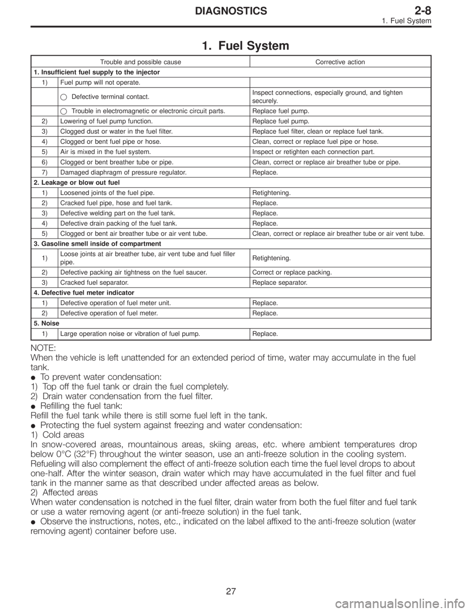
1. Fuel System
Trouble and possible cause Corrective action
1. Insufficient fuel supply to the injector
1) Fuel pump will not operate.
�Defective terminal contact.Inspect connections, especially ground, and tighten
securely.
�Trouble in electromagnetic or electronic circuit parts. Replace fuel pump.
2) Lowering of fuel pump function. Replace fuel pump.
3) Clogged dust or water in the fuel filter. Replace fuel filter, clean or replace fuel tank.
4) Clogged or bent fuel pipe or hose. Clean, correct or replace fuel pipe or hose.
5) Air is mixed in the fuel system. Inspect or retighten each connection part.
6) Clogged or bent breather tube or pipe. Clean, correct or replace air breather tube or pipe.
7) Damaged diaphragm of pressure regulator. Replace.
2. Leakage or blow out fuel
1) Loosened joints of the fuel pipe. Retightening.
2) Cracked fuel pipe, hose and fuel tank. Replace.
3) Defective welding part on the fuel tank. Replace.
4) Defective drain packing of the fuel tank. Replace.
5) Clogged or bent air breather tube or air vent tube. Clean, correct or replace air breather tube or air vent tube.
3. Gasoline smell inside of compartment
1)Loose joints at air breather tube, air vent tube and fuel filler
pipe.Retightening.
2) Defective packing air tightness on the fuel saucer. Correct or replace packing.
3) Cracked fuel separator. Replace separator.
4. Defective fuel meter indicator
1) Defective operation of fuel meter unit. Replace.
2) Defective operation of fuel meter. Replace.
5. Noise
1) Large operation noise or vibration of fuel pump. Replace.
NOTE:
When the vehicle is left unattended for an extended period of time, water may accumulate in the fuel
tank.
�To prevent water condensation:
1) Top off the fuel tank or drain the fuel completely.
2) Drain water condensation from the fuel filter.
�Refilling the fuel tank:
Refill the fuel tank while there is still some fuel left in the tank.
�Protecting the fuel system against freezing and water condensation:
1) Cold areas
In snow-covered areas, mountainous areas, skiing areas, etc. where ambient temperatures drop
below 0°C (32°F) throughout the winter season, use an anti-freeze solution in the cooling system.
Refueling will also complement the effect of anti-freeze solution each time the fuel level drops to about
one-half. After the winter season, drain water which may have accumulated in the fuel filter and fuel
tank in the manner same as that described under affected areas as below.
2) Affected areas
When water condensation is notched in the fuel filter, drain water from both the fuel filter and fuel tank
or use a water removing agent (or anti-freeze solution) in the fuel tank.
�Observe the instructions, notes, etc., indicated on the label affixed to the anti-freeze solution (water
removing agent) container before use.
27
2-8DIAGNOSTICS
1. Fuel System
Page 596 of 3342

2. Engine
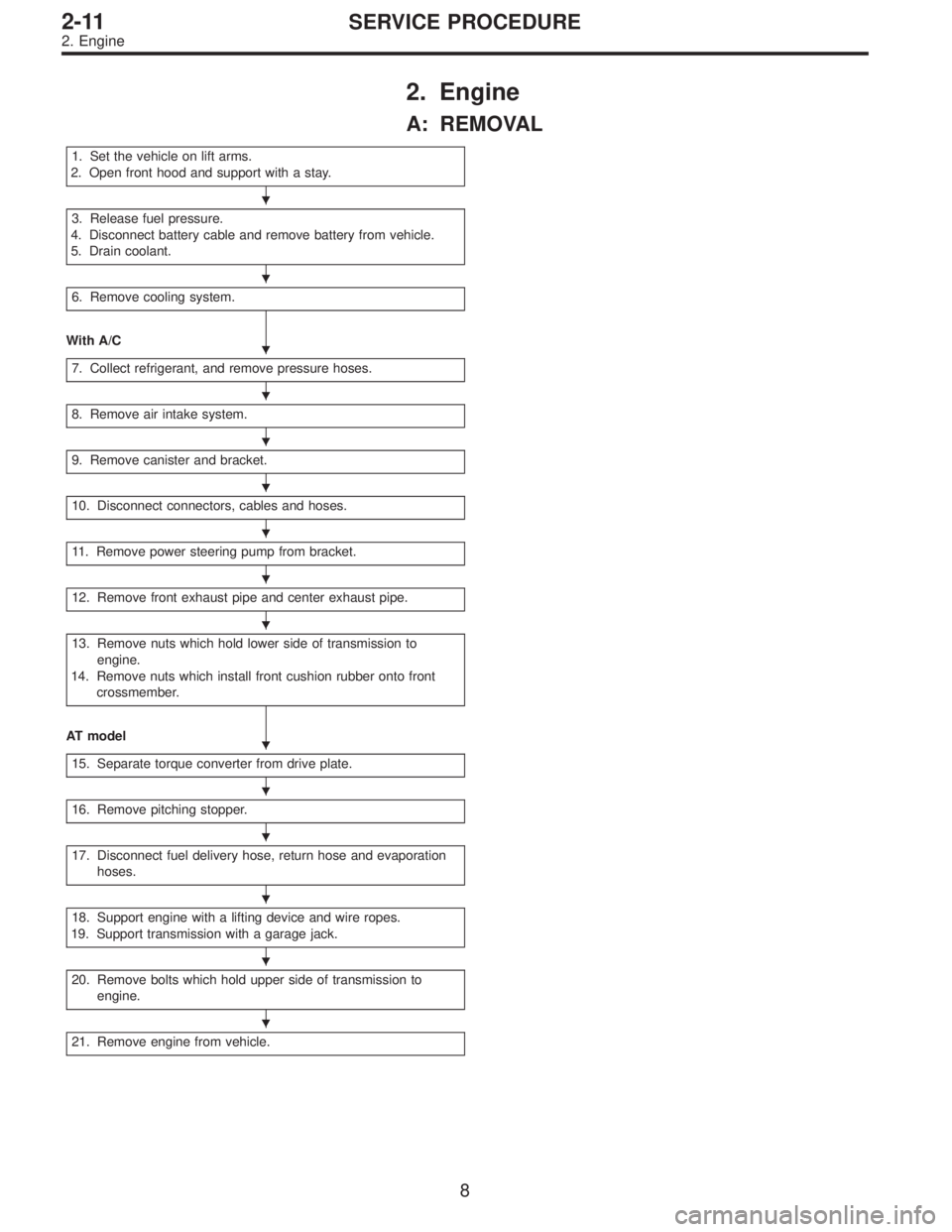
A: REMOVAL
1. Set the vehicle on lift arms.
2. Open front hood and support with a stay.
3. Release fuel pressure.
4. Disconnect battery cable and remove battery from vehicle.
5. Drain coolant.
6. Remove cooling system.
With A/C
7. Collect refrigerant, and remove pressure hoses.
8. Remove air intake system.
9. Remove canister and bracket.
10. Disconnect connectors, cables and hoses.
11. Remove power steering pump from bracket.
12. Remove front exhaust pipe and center exhaust pipe.
13. Remove nuts which hold lower side of transmission to
engine.
14. Remove nuts which install front cushion rubber onto front
crossmember.
AT model
15. Separate torque converter from drive plate.
16. Remove pitching stopper.
17. Disconnect fuel delivery hose, return hose and evaporation
hoses.
18. Support engine with a lifting device and wire ropes.
19. Support transmission with a garage jack.
20. Remove bolts which hold upper side of transmission to
engine.
21. Remove engine from vehicle.
�
�
�
�
�
�
�
�
�
�
�
�
�
�
�
8
2-11SERVICE PROCEDURE
2. Engine
Page 597 of 3342
1) Set the vehicle on lift arms.
2) Open front hood fully and support with stay.
G2M0341
3) Release fuel pressure.
(1) Disconnect fuel tank connector.
(2) Start the engine, and run until it stalls.
(3) After the engine stalls, crank it for five seconds
more.
(4) Turn ignition switch to“OFF”.
G6M0095
4) Disconnect battery cables and remove battery from
vehicle.
B2M0015A
5) Drain coolant.
Set container under the vehicle, and remove drain cock
from radiator.
G2M0263
6) Remove cooling system.
(1) Disconnect radiator fan motor connector.
(2) Disconnect radiator outlet hose from thermostat
cover.
9
2-11SERVICE PROCEDURE
2. Engine
Page 606 of 3342
G2M0294
15) Separate torque converter from drive plate. (AT model)
(1) Lower the vehicle.
(2) Remove service hole plug.
(3) Remove bolts which hold torque converter to drive
plate.
(4) Remove other bolts while rotating the engine using
ST.
ST 499977000 CRANK PULLEY WRENCH
G2M0295
16) Remove pitching stopper.
B2M0336
17) Disconnect fuel delivery hose, return hose and evapo-
ration hose.
CAUTION:
�Disconnect hose with its end wrapped with cloth to
prevent fuel from splashing.
�Catch fuel from hose into container.
G2M0297
18) Support engine with a lifting device and wire ropes.
G2M0298
19) Support transmission with a garage jack.
CAUTION:
Before moving engine away from transmission, check
to be sure no work has been overlooked. Doing this is
very important in order to facilitate re-installation and
because transmission lowers under its own weight.
18
2-11SERVICE PROCEDURE
2. Engine
Page 612 of 3342

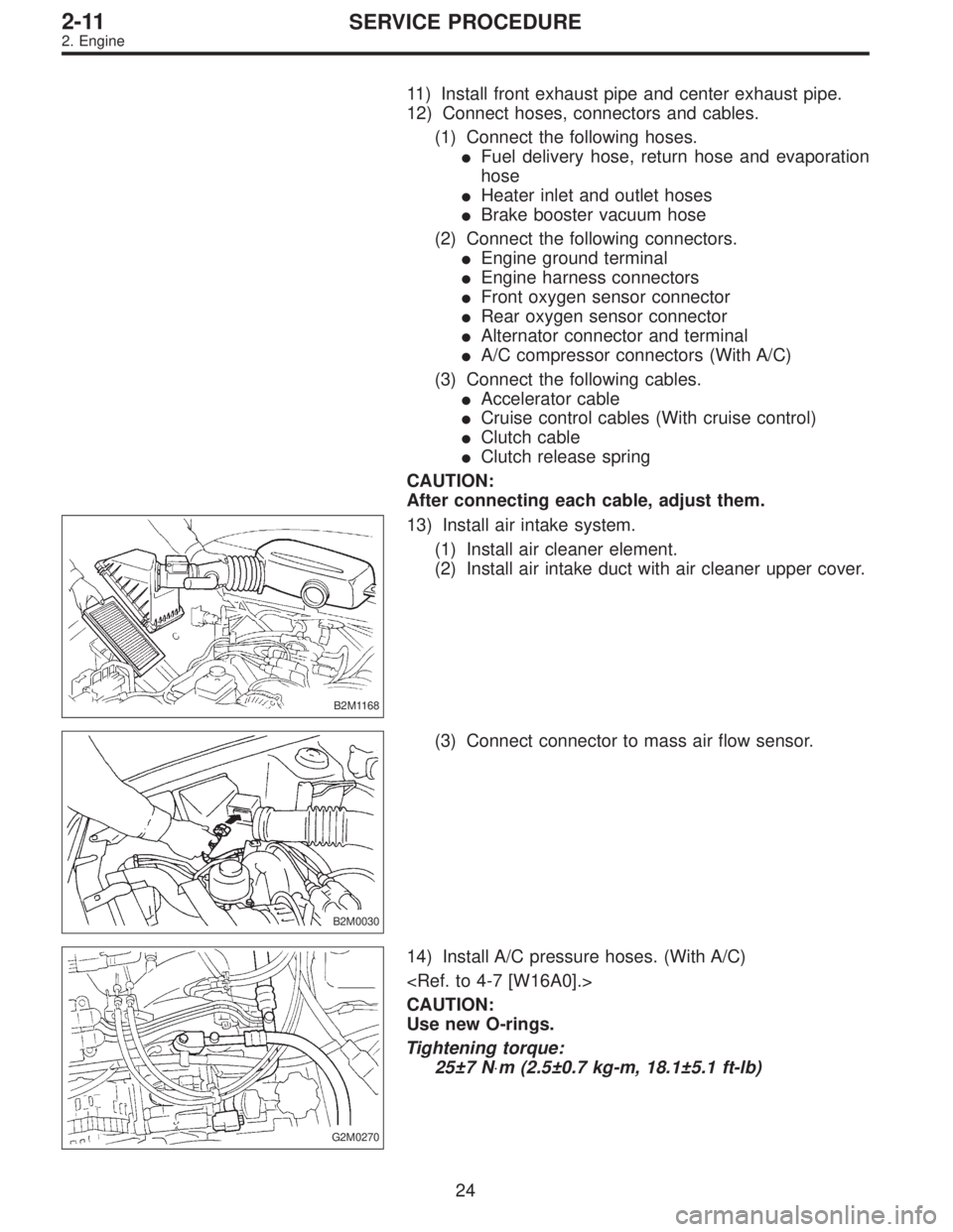
11) Install front exhaust pipe and center exhaust pipe.
12) Connect hoses, connectors and cables.
(1) Connect the following hoses.
�Fuel delivery hose, return hose and evaporation
hose
�Heater inlet and outlet hoses
�Brake booster vacuum hose
(2) Connect the following connectors.
�Engine ground terminal
�Engine harness connectors
�Front oxygen sensor connector
�Rear oxygen sensor connector
�Alternator connector and terminal
�A/C compressor connectors (With A/C)
(3) Connect the following cables.
�Accelerator cable
�Cruise control cables (With cruise control)
�Clutch cable
�Clutch release spring
CAUTION:
After connecting each cable, adjust them.
B2M1168
13) Install air intake system.
(1) Install air cleaner element.
(2) Install air intake duct with air cleaner upper cover.
B2M0030
(3) Connect connector to mass air flow sensor.
G2M0270
14) Install A/C pressure hoses. (With A/C)
CAUTION:
Use new O-rings.
Tightening torque:
25±7 N⋅m (2.5±0.7 kg-m, 18.1±5.1 ft-lb)
24
2-11SERVICE PROCEDURE
2. Engine
Page 1087 of 3342
1. WHEEL ARCH HEIGHT
1) Adjust tire pressure to specifications.
2) Set vehicle under“curb weight”conditions. (Empty lug-
gage compartment, install spare tire, jack, service tools,
and top up fuel tank.)
3) Set steering wheel in a wheel-forward position.
4) Suspend thread from wheel arch (point“A”in figure
below) to determine a point directly above center of
spindle.
5) Measure distance between measuring point and center
of spindle.
B4M0566A
VehiclesSpecified wheel arch height mm (in)
Front Rear
SedanFWD 385
+12
�24(15.16+0.47
�0.94) 369+12
�24(14.53+0.47
�0.94)
AWD 385
+12
�24(15.16+0.47
�0.94) 369+12
�24(14.53+0.47
�0.94)
WagonFWD 385
+12
�24(15.16+0.47
�0.94) 379+12
�24(14.92+0.47
�0.94)
AWD 385
+12
�24(15.16+0.47
�0.94) 379+12
�24(14.92+0.47
�0.94)
OUTBACK AWD 420
+12
�24(16.54+0.47
�0.94) 419+12
�24(16.50+0.47
�0.94)
8
4-1SERVICE PROCEDURE
1. On-car Services
Page 1546 of 3342
B5M0373
3. Fuel Flap
A: REMOVAL
1. FUEL FLAP
Remove bolts which hold hinge to fuel flap, and detach fuel
flap.
B5M0374A
2. FUEL FLAP OPENER
1) Remove rear seats, center pillar lower cover, floor mat,
rear arch cover/rear quarter trim (Wagon), and side sill
cover (on the driver’s side).
2) Remove all clips which hold cable.
3) Disconnect cable from pull handle.
4) Detach pull handle by removing bolts.
5) Detach fuel lock holder by turning it.
B: INSTALLATION
Installation is in the reverse order of removal.
CAUTION:
�When installing cover to pull handle assembly,
observe the following:
�Be careful not to catch harness.
�Engage pull handle assembly pawls firmly.
�Make sure the clearance between fuel flap and
vehicle body is equal at all points.
�After installing opener cable, ensure it moves
smoothly.
37
5-1SERVICE PROCEDURE
3. Fuel Flap