Page 1644 of 3342
1) Remove front seats.
2) Remove rear seat cushion.
3) Remove console box.
4) Remove front pillar lower trim panel.
5) Remove center pillar lower trim panel.
6) Remove side sill cover.
7) Remove fuel opener cover.
G5M0368
8) Remove clip under front seat.
9) Remove clip in toe board area.
NOTE:
When pulling out edge, do not pull mat alone; pull mat
together with edge.
Pry off two steel clips on side sill front cover and one on
side sill rear cover using screwdriver.
10) Remove mat hook.
11) Remove mat from toe board area.
12) Remove mat from heater module.
13) Roll mat, and take it out of opened rear door.
14) Installation is in the reverse order of removal.
NOTE:
�Secure mat firmly with hook and velcro tape.
�Insert mat edge firmly into the groove of side sill cover.
16
5-3SERVICE PROCEDURE
5. Inner Trim Panel
Page 1720 of 3342
 Carbon fouled
Dry fluffy carbon deposits on insulator and electrode are
mostly caused by slow speed driving in city, weak ignition,
too rich fuel mixture, dirty air cleaner, etc.
It is advi")
G6M0088
2) Carbon fouled
Dry fluffy carbon deposits on insulator and electrode are
mostly caused by slow speed driving in city, weak ignition,
too rich fuel mixture, dirty air cleaner, etc.
It is advisable to replace with plugs having hotter heat
range.
G6M0089
3) Oil fouled
Wet black deposits show excessive oil entrance into com-
bustion chamber through worn rings and pistons or exces-
sive clearance between valve guides and stems. If same
condition remains after repair, use a hotter plug.
G6M0090
4) Overheating
White or light gray insulator with black or gray brown spots
and bluish burnt electrodes indicate engine overheating.
Moreover, the appearance results from incorrect ignition
timing, loose spark plugs, wrong selection of fuel, hotter
range plug, etc. It is advisable to replace with plugs having
colder heat range.
G6M0091
C: CLEANING AND REGAPPING
Clean spark plugs in a sand blast type cleaner.
Avoid excessive blasting. Clean and remove carbon or
oxide deposits, but do not wear away porcelain.
If deposits are too stubborn, discard plugs.
After cleaning spark plugs, recondition firing surface of
electrodes with file. Then correct the spark plug gap using
a gap gauge.
Spark plug gap: L
1.0—1.1 mm (0.039—0.043 in)
D: REMOVAL AND INSTALLATION (2500 cc
EXCEPT OUTBACK MODEL)
CAUTION:
All spark plugs installed on an engine, must be of the
same heat range.
Spark plug:
NGK: PFR5B-11
24
6-1SERVICE PROCEDURE
3. Spark Plug
Page 1737 of 3342
, 100 minutes (AT)
Cold cranking ampere 430 amperes (MT), 490 amperes (AT)
Fuse10 A, 15 A, 20 A
Combination
meterSpeedometer")
1. Body Electrical
A: SPECIFICATIONS
BatteryReserve capacity 82 minutes (MT), 100 minutes (AT)
Cold cranking ampere 430 amperes (MT), 490 amperes (AT)
Fuse10 A, 15 A, 20 A
Combination
meterSpeedometer Electric pulse type
Tachometer Electric impulse type
Water temperature gauge Thermistor cross coil type
Fuel gauge Resistance cross coil type
Charge indicator light 12 V—1.4 W
Brake fluid level warning/parking brake indicator light 12 V—1.4 W
AT oil temperature warning light (AWD only) 12 V—1.4 W
ABS warning light 12 V—1.4 W
CHECK ENGINE warning light
(Malfunction indicator lamp)12 V—1.4 W
Oil pressure warning light 12 V—1.4 W
AIRBAG system warning light 12 V—1.4 W
Low fuel warning light 12 V—3W
FWD indicator light 12 V—1.4 W
TCS warning light 12 V—1.4 W
TCS indicator light 12 V—1.4 W
Turn signal indicator light 12 V—1.4 W (2 pieces)
Seat belt warning light 12 V—1.4 W
Door open warning light 12 V—1.4 W (5 pieces)
Headlight beam indicator light 12 V—1.4 W
Meter illumination light12 V—3 W (2 pieces)
12 V—3.4 W (4 pieces)
Headlight 12 V—60/55 W (Halogen)
Front clearance light 12 V—5W
Turn signal lightFront 12 V—21 W
Rear 12 V—21 W
Tail/Stop light 12 V—5/21 W
Back-up light 12 V—21 W
High-mount stop light12 V—18 W (SEDAN), 12 V—13 W
(WAGON)
License plate light 12 V—5W
Room light 12 V—8W
Trunk room light (SEDAN) 12 V—5W
Luggage room light (WAGON) 12 V—5W
Spot light 12 V—8 W (2 pieces)
Glove box light 12 V—3.4 W
Ash tray illumination light 12 V—1.7 W
Selector lever illumination light (AT model) 12 V—1.7 W
2
6-2SPECIFICATIONS
1. Body Electrical
Page 1776 of 3342
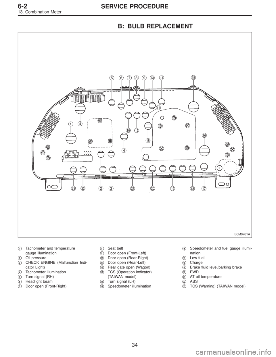
B: BULB REPLACEMENT
B6M0761A
�1Tachometer and temperature
gauge illumination
�
2Oil pressure
�
3CHECK ENGINE (Malfunction Indi-
cator Light)
�
4Tachometer illumination
�
5Turn signal (RH)
�
6Headlight beam
�
7Door open (Front-Right)�
8Seat belt
�
9Door open (Front-Left)
�
10Door open (Rear-Right)
�
11Door open (Rear-Left)
�
12Rear gate open (Wagon)
�
13TCS (Operation indicator)
(TAIWAN model)
�
14Turn signal (LH)
�
15Speedometer illumination�
16Speedometer and fuel gauge illumi-
nation
�
17Low fuel
�
18Charge
�
19Brake fluid level/parking brake
�
20FWD
�
21AT oil temperature
�
22ABS
�
23TCS (Warning) (TAIWAN model)
34
6-2SERVICE PROCEDURE
13. Combination Meter
Page 1853 of 3342
 system detects and
indicates a fault in various inputs and outputs of the com-
plex electronic control. CHECK ENGINE malfunction indi-")
1. General
1. GENERAL DESCRIPTION
�The on-board diagnostics (OBD) system detects and
indicates a fault in various inputs and outputs of the com-
plex electronic control. CHECK ENGINE malfunction indi-
cator lamp (MIL) in the combination meter indicates occur-
rence of a fault or trouble.
�Further, against such a failure or sensors as may disable
the drive, the fail-safe function is provided to ensure the
minimal driveability.
�The OBD system incorporated with the vehicles within
this engine family complies with Section 1968.1, California
Code of Regulations (OBD-II regulation). The OBD system
monitors the components and the system malfunction
listed in Engine Section which affects on emissions.
�When the system decides that a malfunction occurs, MIL
illuminates. At the same time of the MIL illumination or
blinking, a diagnostic trouble code (DTC) and a freeze
frame engine conditions are stored into on-board com-
puter.
�The OBD system stores freeze frame engine condition
data (engine load, engine coolant temperature, fuel trim,
engine speed and vehicle speed, etc.) into on-board com-
puter when it detects a malfunction first.
�If the OBD system detects the various malfunctions
including the fault of fuel trim or misfire, the OBD system
first stores freeze frame engine conditions about the fuel
trim or misfire.
�When the malfunction does not occur again for three
consecutive driving cycles, MIL is turned off, but DTC
remains at on-board computer.
�The OBD-II system is capable of communication with a
general scan tool (OBD-II general scan tool) formed by ISO
9141 CARB.
�The OBD-II diagnostics procedure is different from the
usual diagnostics procedure. When troubleshooting OBD-II
vehicles, connect Subaru select monitor or the OBD-II gen-
eral scan tool to the vehicle.
A: ENGINE
1. ENGINE AND EMISSION CONTROL SYSTEM
�The Multipoint Fuel Injection (MFI) system is a system
that supplies the optimum air-fuel mixture to the engine for
all the various operating conditions through the use of the
latest electronic technology.
With this system fuel, which is pressurized at a constant
pressure, is injected into the intake air passage of the cyl-
inder head. The injection quantity of fuel is controlled by an
intermittent injection system where the electro-magnetic
injection valve (fuel injector) opens only for a short period
of time, depending on the quantity of air required for one
cycle of operation. In actual operation, the injection quan-
2
2-7ON-BOARD DIAGNOSTICS II SYSTEM
1. General
Page 1854 of 3342
tity is determined by the duration of an electric pulse
applied to the fuel injector and this permits simple, yet
highly precise metering of the fuel.
�Further, all the operating conditions of the engine are
converted into electric signals, and this results in additional
features of the system, such as large improved
adaptability, easier addition of compensating element, etc.
The MFI system also has the following features:
1) Reduced emission of harmful exhaust gases.
2) Reduced in fuel consumption.
3) Increased engine output.
4) Superior acceleration and deceleration.
5) Superior startability and warm-up performance in cold
weather since compensation is made for coolant and
intake air temperature.
3
2-7ON-BOARD DIAGNOSTICS II SYSTEM
1. General
Page 1856 of 3342

�
2Ignition coil
�
3Ignitor
�
4Crankshaft position sensor
�
5Camshaft position sensor
�
6Throttle position sensor
�
7Fuel injectors
�
8Pressure regulator
�
9Engine coolan")
�1Engine control module (ECM)
�
2Ignition coil
�
3Ignitor
�
4Crankshaft position sensor
�
5Camshaft position sensor
�
6Throttle position sensor
�
7Fuel injectors
�
8Pressure regulator
�
9Engine coolant temperature sensor
�
10Mass air flow sensor
�
11Idle air control solenoid valve
�
12Purge control solenoid valve
�
13Fuel pump
�
14PCV valve
�
15Air cleaner
�
16Canister
�
17Main relay
�
18Fuel pump relay
�
19Fuel filter
�
20Front catalytic converter
�
21Rear catalytic converter
�
22EGR valve (AT vehicles only)
�
23EGR control solenoid valve (AT vehicles only)
�
24Radiator fan�
25Radiator fan relay
�
26Pressure sources switching solenoid valve
�
27Knock sensor
�
28Back-pressure transducer (AT vehicles only)
�
29Front oxygen sensor
�
30Rear oxygen sensor (2200 cc Federal spec. vehicles)
�
31Pressure sensor
�
32A/C compressor
�
33Inhibitor switch
�
34CHECK ENGINE malfunction indicator lamp (MIL)
�
35Tachometer
�
36A/C relay
�
37A/C control module
�
38Ignition switch
�
39Transmission control module (TCM) (AT vehicles only)
�
40ABS/TCS control module (TCS equipped models)
�
41Vehicle speed sensor
�
42Data link connector (For Subaru select monitor)
�
43Data link connector (For Subaru select monitor and OBD-II
general scan tool)
�
44Two way valve
�
45Rear oxygen sensor (2200 cc California spec. vehicles)
�
46Filter
5
2-7ON-BOARD DIAGNOSTICS II SYSTEM
1. General
Page 1858 of 3342

�
2Ignition coil
�
3Ignitor
�
4Crankshaft position sensor
�
5Camshaft position sensor
�
6Throttle position sensor
�
7Fuel injectors
�
8Pressure regulator
�
9Engine coolan")
�1Engine control module (ECM)
�
2Ignition coil
�
3Ignitor
�
4Crankshaft position sensor
�
5Camshaft position sensor
�
6Throttle position sensor
�
7Fuel injectors
�
8Pressure regulator
�
9Engine coolant temperature sensor
�
10Mass air flow sensor
�
11Idle air control solenoid valve
�
12Purge control solenoid valve
�
13Fuel pump
�
14PCV valve
�
15Air cleaner
�
16Canister
�
17Main relay
�
18Fuel pump relay
�
19Fuel filter
�
20Front catalytic converter
�
21Rear catalytic converter
�
22EGR valve (AT vehicles only)
�
23EGR control solenoid valve (AT vehicles only)
�
24Radiator fan
�
25Radiator fan relay
�
26Pressure sources switching solenoid valve�
27Front oxygen sensor
�
28Rear oxygen sensor (2200 cc Federal spec. vehicles)
�
29Pressure sensor
�
30A/C compressor (With A/C models)
�
31Inhibitor switch
�
32CHECK ENGINE malfunction indicator lamp (MIL)
�
33Tachometer
�
34A/C relay (With A/C models)
�
35A/C control module (With A/C models)
�
36Ignition switch
�
37Transmission control module (TCM)
�
38Vehicle speed sensor
�
39Data link connector (For Subaru select monitor)
�
40Data link connector (For Subaru select monitor and OBD-II
general scan tool)
�
41Rear oxygen sensor (2200 cc California spec. vehicles)
�
42Knock sensor
�
43Back-pressure transducer (AT vehicles only)
�
44Filter
�
45Fuel tank pressure sensor
�
46Pressure control solenoid valve
�
47Fuel temperature sensor
�
48Fuel level sensor
�
49Vent control solenoid valve
�
50Air filter
7
2-7ON-BOARD DIAGNOSTICS II SYSTEM
1. General
![SUBARU LEGACY 1997 Service Repair Manual <Ref. to 5-3 [C500].>
1) Remove front seats.
2) Remove rear seat cushion.
3) Remove console box.
4) Remove front pillar lower trim panel.
5) Remove center pillar lower trim panel.
6) Remove side sill](/manual-img/17/57434/w960_57434-1643.png "SUBARU LEGACY 1997 Service Repair Manual <Ref. to 5-3 [C500].>
1) Remove front seats.
2) Remove rear seat cushion.
3) Remove console box.
4) Remove front pillar lower trim panel.
5) Remove center pillar lower trim panel.
6) Remove side sill")