Page 1965 of 3342
 Turn ignition switch to OFF.
2) Measure resistance of harness connector between fuel
pump and fuel pump relay.
: Connect")
B2M0526A
8E4CHECK HARNESS BETWEEN FUEL
PUMP AND FUEL PUMP RELAY CON-
NECTOR.
1) Turn ignition switch to OFF.
2) Measure resistance of harness connector between fuel
pump and fuel pump relay.
: Connector & terminal
(R58) No. 1—(B46) No. 4:
Is the resistance less than 1Ω?
: Go to next.
: Repair open circuit in harness between fuel pump
and fuel pump relay connector.
: Connector & terminal
(R58) No. 1—Chassis ground:
Is the resistance more than 1 MΩ?
: Go to step8E5.
: Repair short circuit in harness between fuel pump
and fuel pump relay connector.
G2M0461
8E5
CHECK FUEL PUMP RELAY.
1) Disconnect connectors from fuel pump relay and main
relay.
2) Remove fuel pump relay and main relay with bracket.
3) Connect battery to fuel pump relay connector terminals
No. 1 and No. 3.
4) Measure resistance between connector terminals of
fuel pump relay.
: Terminals
No. 2—No. 4:
Is the resistance less than 10Ω?
: Go to step8E6.
: Replace fuel pump relay.
11 4
2-7ON-BOARD DIAGNOSTICS II SYSTEM
8. Diagnostics for Engine Starting Failure
Page 1966 of 3342
B2M0527A
8E6CHECK HARNESS BETWEEN ECM AND
FUEL PUMP RELAY CONNECTOR.
1) Disconnect connectors from ECM.
2) Measure resistance of harness between ECM and fuel
pump relay connector.
: Connector & terminal
(B84) No. 32—(B46) No. 3:
Is the resistance less than 1Ω?
: Go to next.
: Repair open circuit in harness between ECM and
fuel pump relay connector.
: Is there poor contact in ECM connector?
: Repair poor contact in ECM connector.
: Check fuel injector circuit.
11 5
2-7ON-BOARD DIAGNOSTICS II SYSTEM
8. Diagnostics for Engine Starting Failure
Page 1967 of 3342
F: FUEL PUMP CIRCUIT (2200 cc AWD
EXCEPT TAIWAN SPEC. VEHICLES)
WIRING DIAGRAM:
B2M1053
CAUTION:
After repair or replacement of faulty parts, conduct
CLEAR MEMORY and INSPECTION MODES.
11 6
2-7ON-BOARD DIAGNOSTICS II SYSTEM
8. Diagnostics for Engine Starting Failure
Page 1968 of 3342

8F1CHECK OPERATING SOUND OF FUEL
PUMP.
Make sure that fuel pump is in operation for two seconds
when turning ignition switch to ON.
: Does fuel pump produce operating sound?
NOTE:
Fuel pump operation check can also be executed using
Subaru Select Monitor (Function mode: FD01).
For the procedure, refer to“COMPULSORY VALVE
OPERATION CHECK MODE”.
: Check fuel injector circuit.
: Go to step8F2.
OBD0132A
8F2CHECK GROUND CIRCUIT OF FUEL
PUMP.
1) Turn ignition switch to OFF.
2) Disconnect connector from fuel pump.
3) Measure resistance of harness connector between fuel
pump and chassis ground.
: Connector & terminal
(R58) No. 4—Chassis ground:
Is the resistance less than 5Ω?
: Go to step8F3.
: Repair open circuit in fuel pump ground circuit.
OBD0133A
8F3
CHECK POWER SUPPLY TO FUEL PUMP.
1) Turn ignition switch to ON.
2) Measure voltage of power supply circuit between fuel
pump connector and chassis ground.
: Connector & terminal
(R58) No. 1 (+)—Chassis ground (�):
Is the voltage more than 10 V?
: Replace fuel pump.
: Go to step8F4.
11 7
2-7ON-BOARD DIAGNOSTICS II SYSTEM
8. Diagnostics for Engine Starting Failure
Page 1969 of 3342
 Turn ignition switch to OFF.
2) Measure resistance of harness connector between fuel
pump and fuel pump relay.
: Connect")
B2M0526A
8F4CHECK HARNESS BETWEEN FUEL
PUMP AND FUEL PUMP RELAY CON-
NECTOR.
1) Turn ignition switch to OFF.
2) Measure resistance of harness connector between fuel
pump and fuel pump relay.
: Connector & terminal
(R58) No. 1—(B46) No. 4:
Is the resistance less than 1Ω?
: Go to next.
: Repair open circuit in harness between fuel pump
and fuel pump relay connector.
: Connector & terminal
(R58) No. 1—Chassis ground:
Is the resistance more than 1 MΩ?
: Go to step8F5.
: Repair short circuit in harness between fuel pump
and fuel pump relay connector.
G2M0461
8F5
CHECK FUEL PUMP RELAY.
1) Disconnect connectors from fuel pump relay and main
relay.
2) Remove fuel pump relay and main relay with bracket.
3) Connect battery to fuel pump relay connector terminals
No. 1 and No. 3.
4) Measure resistance between connector terminals of
fuel pump relay.
: Terminals
No. 2—No. 4:
Is the resistance less than 10Ω?
: Go to step8F6.
: Replace fuel pump relay.
11 8
2-7ON-BOARD DIAGNOSTICS II SYSTEM
8. Diagnostics for Engine Starting Failure
Page 1970 of 3342
B2M0527A
8F6CHECK HARNESS BETWEEN ECM AND
FUEL PUMP RELAY CONNECTOR.
1) Disconnect connectors from ECM.
2) Measure resistance of harness between ECM and fuel
pump relay connector.
: Connector & terminal
(B84) No. 32—(B46) No. 3:
Is the resistance less than 1Ω?
: Go to next.
: Repair open circuit in harness between ECM and
fuel pump relay connector.
: Is there poor contact in ECM connector?
: Repair poor contact in ECM connector.
: Check fuel injector circuit.
11 9
2-7ON-BOARD DIAGNOSTICS II SYSTEM
8. Diagnostics for Engine Starting Failure
Page 1971 of 3342
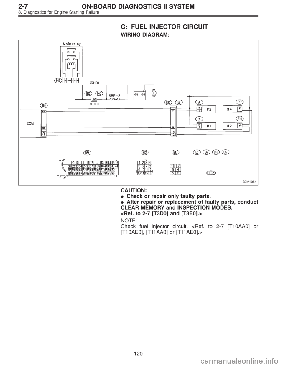
G: FUEL INJECTOR CIRCUIT
WIRING DIAGRAM:
B2M1054
CAUTION:
�Check or repair only faulty parts.
�After repair or replacement of faulty parts, conduct
CLEAR MEMORY and INSPECTION MODES.
NOTE:
Check fuel injector circuit.
[T10AE0], [T11AA0] or [T11AE0].>
120
2-7ON-BOARD DIAGNOSTICS II SYSTEM
8. Diagnostics for Engine Starting Failure
Page 1974 of 3342
![SUBARU LEGACY 1997 Service Repair Manual 9. General Diagnostic Table
A: GENERAL DIAGNOSTICS TABLE WITH
NONCONFORMITY SYMPTOM FOR ENGINE
NOTE:
Malfunction of parts other than those listed is also possible.
<Ref. to 2-3 [K100], 2-3b [K100].>
S](/manual-img/17/57434/w960_57434-1973.png "SUBARU LEGACY 1997 Service Repair Manual 9. General Diagnostic Table
A: GENERAL DIAGNOSTICS TABLE WITH
NONCONFORMITY SYMPTOM FOR ENGINE
NOTE:
Malfunction of parts other than those listed is also possible.
<Ref. to 2-3 [K100], 2-3b [K100].>
S")
9. General Diagnostic Table
A: GENERAL DIAGNOSTICS TABLE WITH
NONCONFORMITY SYMPTOM FOR ENGINE
NOTE:
Malfunction of parts other than those listed is also possible.
Symptom Problem parts
1. Engine stalls during idling.1) Idle air control solenoid valve
2) Mass air flow sensor
3) Ignition parts (*1)
4) Engine coolant temperature sensor (*2)
5) Crankshaft position sensor (*3)
6) Camshaft position sensor (*3)
7) EGR valve
8) Fuel injection parts (*4)
2. Rough idling1) Idle air control solenoid valve
2) Mass air flow sensor
3) Engine coolant temperature sensor (*2)
4) Ignition parts (*1)
5) Air intake system (*5)
6) Fuel injection parts (*4)
7) Throttle position sensor
8) Crankshaft position sensor (*3)
9) Camshaft position sensor (*3)
10) EGR valve
11) Oxygen sensor
12) Fuel pump and fuel pump relay
3. Engine does not return to idle.1) Idle air control solenoid valve
2) Engine coolant temperature sensor
3) Accelerator cable (*6)
4) Throttle position sensor
5) Mass air flow sensor
4. Poor acceleration1) Mass air flow sensor
2) Throttle position sensor
3) Fuel injection parts (*4)
4) Fuel pump and fuel pump relay
5) Engine coolant temperature sensor (*2)
6) Crankshaft position sensor (*3)
7) Camshaft position sensor (*3)
8) A/C switch and A/C cut relay
9) Engine torque control signal circuit
10) Ignition parts (*1)
5. Engine stalls or engine sags or hesitates at
acceleration.1) Mass air flow sensor
2) Engine coolant temperature sensor (*2)
3) Crankshaft position sensor (*3)
4) Camshaft position sensor (*3)
5) Purge control solenoid valve
6) EGR valve
7) Fuel injection parts (*4)
8) Throttle position sensor
9) Fuel pump and fuel pump relay
6. Surge1) Mass air flow sensor
2) Engine coolant temperature sensor (*2)
3) Crankshaft position sensor (*3)
4) Camshaft position sensor (*3)
5) EGR valve
6) Fuel injection parts (*4)
7) Throttle position sensor
8) Fuel pump and fuel pump relay
123
2-7ON-BOARD DIAGNOSTICS II SYSTEM
9. General Diagnostic Table
 Disconnect connectors from ECM.
2) Measure resistance of harness between ECM and fuel
pump relay connector.
: Connector & termin")

WIRING DIAGRAM:
B2M1053
CAUTION:
After repair or replacement of faulty parts, conduct
CLEAR MEMORY and INSPECTION MODES.
<Ref. to 2-7 [T")
 Disconnect connectors from ECM.
2) Measure resistance of harness between ECM and fuel
pump relay connector.
: Connector & termin")