Page 1644 of 2053

SSANGYONG MY2002
8B-62 SUPPLEMENTAL RESTRAINTS SYSTEM
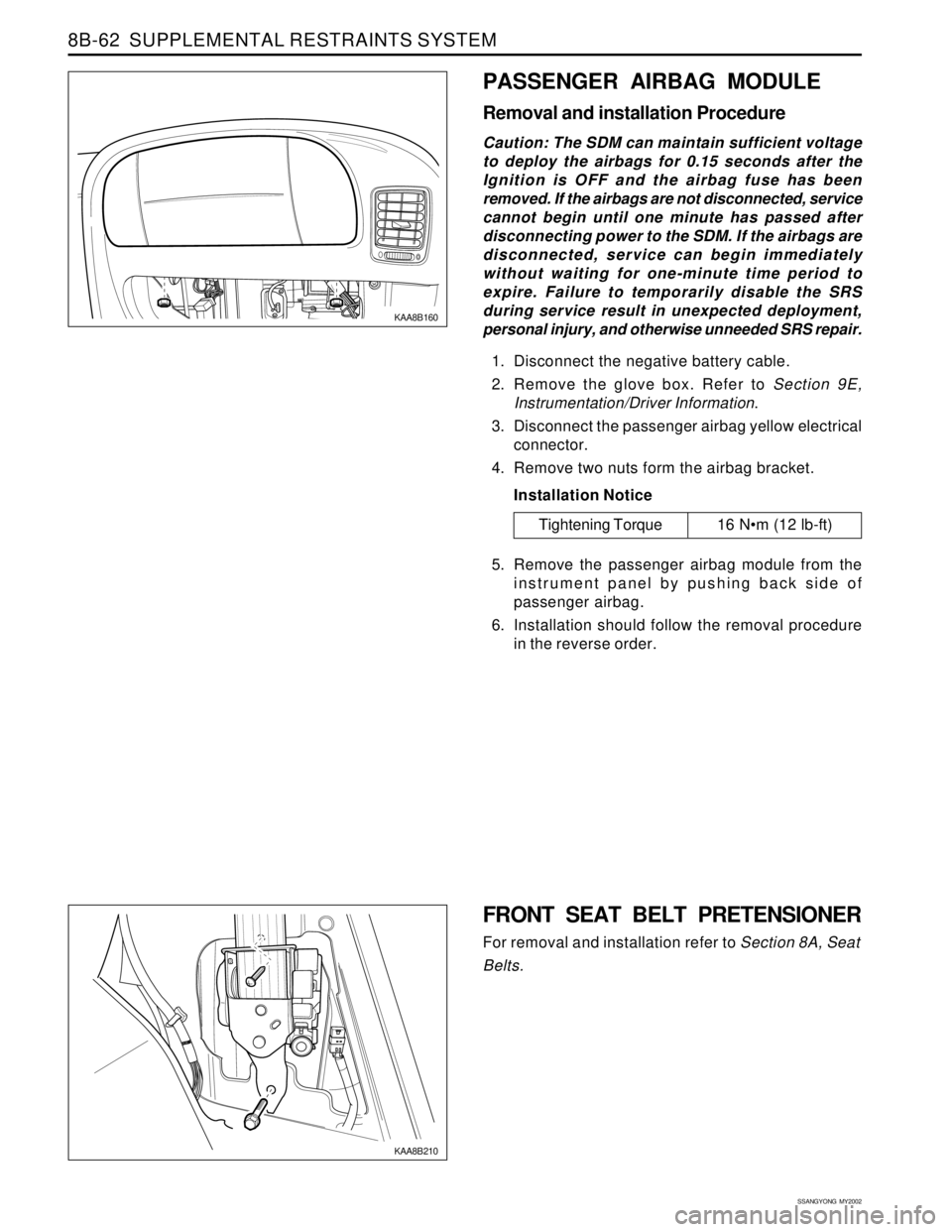
KAA8B160
PASSENGER AIRBAG MODULE
Removal and installation Procedure
Caution: The SDM can maintain sufficient voltage
to deploy the airbags for 0.15 seconds after the
Ignition is OFF and the airbag fuse has been
removed. If the airbags are not disconnected, service
cannot begin until one minute has passed after
disconnecting power to the SDM. If the airbags are
disconnected, service can begin immediately
without waiting for one-minute time period to
expire. Failure to temporarily disable the SRS
during service result in unexpected deployment,
personal injury, and otherwise unneeded SRS repair.
1. Disconnect the negative battery cable.
2. Remove the glove box. Refer to Section 9E,
Instrumentation/Driver Information.
3. Disconnect the passenger airbag yellow electrical
connector.
4. Remove two nuts form the airbag bracket.
Installation Notice
5. Remove the passenger airbag module from the
instrument panel by pushing back side of
passenger airbag.
6. Installation should follow the removal procedure
in the reverse order.
Tightening Torque 16 Nm (12 lb-ft)
FRONT SEAT BELT PRETENSIONER
For removal and installation refer to Section 8A, Seat
Belts.
KAA8B210
Page 1689 of 2053
LIGHTING SYSTEM 9B-15
SSANGYONG MY2002
REPAIR INSTRUCTIONS
KAA9B020
KAA9B030
ON-VEHICLE SERVICE
UNIT REPAIR
HEAD LAMPS
Removal and Installation Procedure
1. Open the hood.
2. Disconnect the negative battery cable.
3. Remove screws and row the radiator grille.
Installation Notice
Dissimilar metals in direct contact with each
other may corrode rapidly. Make sure to use
the correct fasteners to prevent premature
corrosion.
4. Disconnect the headlamp assembly electrical con-
nector.
5. Remove the headlamp.
Installation Notice
Dissimilar metals in direct contact with each
other may corrode rapidly. Make sure to use
the correct fasteners to prevent premature
corrosion.
Tightening Torque5 - 9 Nm
(44 - 80 lb-in)
Tightening Torque5 - 9 Nm
(44 - 80 lb-in)
KAA9B040
6. Turn the headlamp bulb locker and remove the
headlamp bulb.
7. Installation should follow the removal procedure
in the reverse order.
Page 1690 of 2053
SSANGYONG MY2002
9B-16 LIGHTING SYSTEM
KAA9B050
KAA9B060
FRONT COMBINATION LAMP
Removal and Installation Procedure
1. Disconnect negative battery cable.
2. Remove the screws and nuts.
Installation Notice
Dissimilar metals in direct contact with each
other may corrode rapidly. Make sure to use
the correct fasteners to prevent premature
corrosion.
Tightening Torque5 - 9 Nm
(44 - 80 lb-in)
KAA9B080
KAA9B090
CENTER HIGH-MOUNTED STOP
LAMP
Removal and Installation Procedure
1. Disconnect the negative battery cable.
2. Remove the center high-mounted stop lamp cover
3. Disconnect the CHMSL electrical connector.
4. Remove the screws with the CHMSL
5. Installation should follow the removal procedure
in the reverse order. 3. Disconnect and remover the front combination
lamp.
4. Remove the inoperative bulb.
5. Installation should follow the removal procedure
in the reverse order.
Page 1691 of 2053
LIGHTING SYSTEM 9B-17
SSANGYONG MY2002
KAA9B070
REAR COMBINATION LAMPS
Removal and Installation Procedure
1. Disconnect the negative battery cable.
2. Remove the screws and the lamp assembly
3. Remove any inoperative bulb.
4. Installation should follow the removal procedure
in the reverse order.
KAA9B100
FOG LAMPS
Removal and Installation Procedure
1. Disconnect the negative battery cable.
2. Remove the bolts that secure the fog lamp
assembly
Installation Notice
Dissimilar metals in direct contact with each
other may corrode rapidly. Make sure to use
the correct fasteners to prevent premature
corrosion.
3. Remove the fog assembly.
4. Disconnect the fog lamp assembly electrical
connector.
Tightening Torque5 - 9 Nm
(44 - 80 lb-in)
KAA9B110
5. Remove the fog lamp dust cover.
6. Remove the locking clip.
7. Remove the bulb fromthefog lamp assembly.
8. Disconnect the bulb electrical connector.
9. Installation should follow the removal procedure
in the reverse order.
Page 1713 of 2053

WIPER, WASHER SYSTEMS 9D-5
SSANGYONG MY2002
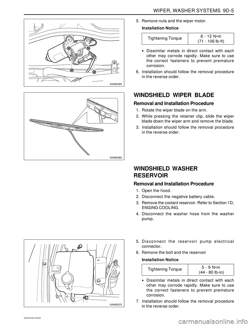
KAA9D050
KAA9D060
5. Remove nuts and the wiper motor.
Installation Notice
Dissimilar metals in direct contact with each
other may corrode rapidly. Make sure to use
the correct fasteners to prevent premature
corrosion.
6. Installation should follow the removal procedure
in the reverse order.
WINDSHIELD WASHER
RESERVOIR
Removal and Installation Procedure
1. Open the hood.
2. Disconnect the negative battery cable.
3. Remove the coolant reservoir. Refer to Section 1D,
ENGING COOLING.
4. Disconnect the washer hose from the washer
pump.
WINDSHIELD WIPER BLADE
Removal and Installation Procedure
1. Rotate the wiper blade on the arm.
2. While pressing the retainer clip, slide the wiper
blade down the wiper arm and remove the blade.
3. Installation should follow the removal procedure
in the reverse order.
Tightening Torque8 - 12 Nm
(71 - 106 lb-ft)
KAA9D070
5. Disconnect the reservoir pump electrical
connector.
6. Remove the bolt and the reservoir
Installation Notice
Dissimilar metals in direct contact with each
other may corrode rapidly. Make sure to use
the correct fasteners to prevent premature
corrosion.
7. Installation should follow the removal procedure
in the reverse order.
Tightening Torque5 - 9 Nm
(44 - 80 lb-in)
Page 1714 of 2053

SSANGYONG MY2002
9D-6 WIPER, WASHER SYSTEMS
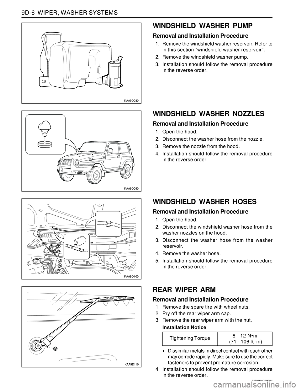
KAA9D080
KAA9D090
KAA9D100
WINDSHIELD WASHER PUMP
Removal and Installation Procedure
1. Remove the windshield washer reservoir. Refer to
in this section “windshield washer reservoir”.
2. Remove the windshield washer pump.
3. Installation should follow the removal procedure
in the reverse order.
WINDSHIELD WASHER HOSES
Removal and Installation Procedure
1. Open the hood.
2. Disconnect the windshield washer hose from the
washer nozzles on the hood.
3. Disconnect the washer hose from the washer
reservoir.
4. Remove the washer hose.
5. Installation should follow the removal procedure
in the reverse order.
KAA9D110
REAR WIPER ARM
Removal and Installation Procedure
1. Remove the spare tire with wheel nuts.
2. Pry off the rear wiper arm cap.
3. Remove the rear wiper arm with the nut.
Installation Notice
Dissimilar metals in direct contact with each other
may corrode rapidly. Make sure to use the correct
fasteners to prevent premature corrosion.
4. Installation should follow the removal procedure
in the reverse order.
WINDSHIELD WASHER NOZZLES
Removal and Installation Procedure
1. Open the hood.
2. Disconnect the washer hose from the nozzle.
3. Remove the nozzle from the hood.
4. Installation should follow the removal procedure
in the reverse order.
Tightening Torque8 - 12 Nm
(71 - 106 lb-in)
Page 1715 of 2053

WIPER, WASHER SYSTEMS 9D-7
SSANGYONG MY2002
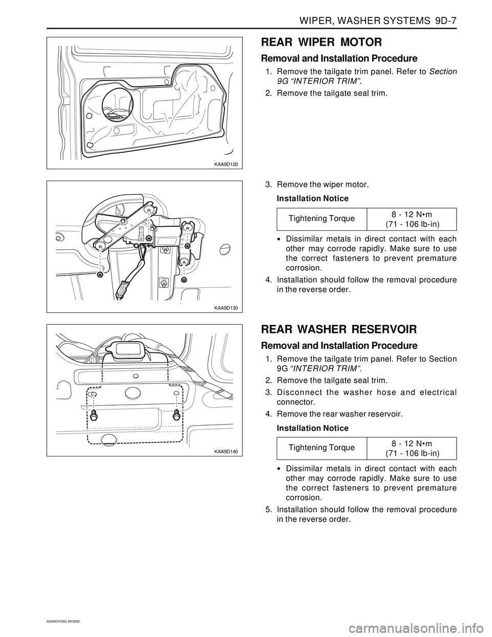
KAA9D120
KAA9D130
REAR WIPER MOTOR
Removal and Installation Procedure
1. Remove the tailgate trim panel. Refer to Section
9G “INTERIOR TRIM”.
2. Remove the tailgate seal trim.
3. Remove the wiper motor.
Installation Notice
Dissimilar metals in direct contact with each
other may corrode rapidly. Make sure to use
the correct fasteners to prevent premature
corrosion.
4. Installation should follow the removal procedure
in the reverse order.
Tightening Torque8 - 12 Nm
(71 - 106 lb-in)
KAA9D140
REAR WASHER RESERVOIR
Removal and Installation Procedure
1. Remove the tailgate trim panel. Refer to Section
9G “INTERIOR TRIM”.
2. Remove the tailgate seal trim.
3. Disconnect the washer hose and electrical
connector.
4. Remove the rear washer reservoir.
Installation Notice
Dissimilar metals in direct contact with each
other may corrode rapidly. Make sure to use
the correct fasteners to prevent premature
corrosion.
5. Installation should follow the removal procedure
in the reverse order.
Tightening Torque8 - 12 Nm
(71 - 106 lb-in)
Page 1754 of 2053
INTERIOR TRIM 9G-5
SSANGYONG MY2002
EF
KAA9G060
KAA9G050
A-PILLAR TRIM PANEL
Removal and Installation Procedure
1. Remove the roof assist handle with the screws.
2. Remove the A-pillar trim panel.
3. Installation should follow the removal procedure
in the reverse order. 6. Disconnect the electrical connector.
7. Remove the door trim panel.
8. Installation should follow the removal procedure
in the reverse order.
KAA9G080
KAA9G070
3. Remove the upper quarter trim panel.
4. Installation should follow the removal procedure
in the reverse order.
UPPER QUARTER TRIM PANEL
Removal and Installation Procedure
1. Remove the roof assist handle with the screws.
2. Remove the seat belt anchor with the bolt.
Installation Notice
•Dissimilar metals in direct contact with each
other may corrode rapidly. Make sure to use
the correct fasteners to prevent premature
corrosion.
Tightening Torque 45 Nm (33 lb-ft)