1997 SSANGYONG KORANDO ignition
[x] Cancel search: ignitionPage 1375 of 2053
TRANSFER CASE 5D1-5
SSANGYONG MY2002
The motor reaches its destination.
The motor is on for 5 seconds without reaching its
destination. The shift has failed and the TCCU will
respond as default mode.
A fault occurs with either the motor or position
encoder. Refer to the diagnosis requirement.
When the motor is energized, the Ignition, 4H/4L
switch, propeller shaft speeds, and transmission
neutral inputs are ignored.
Indicator Function
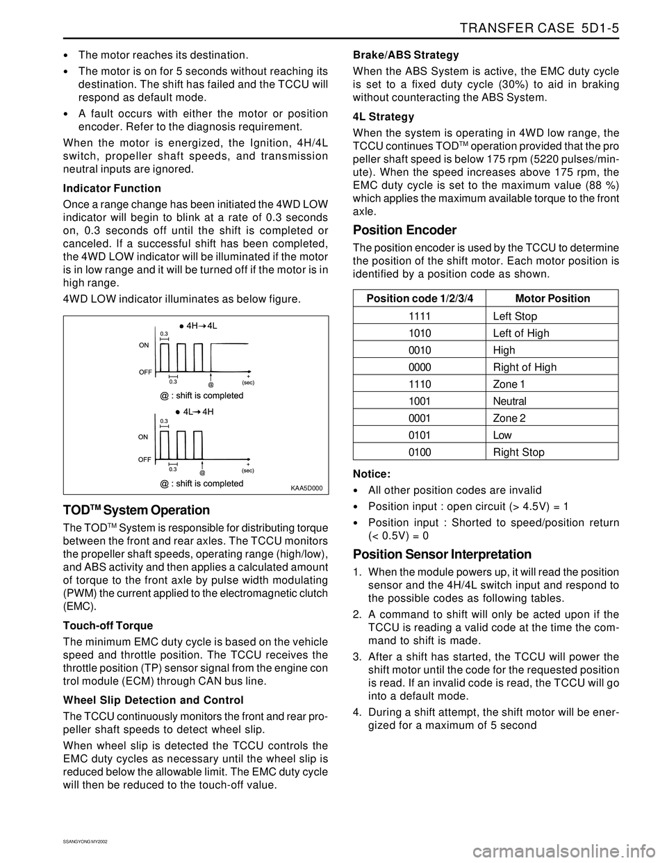
Once a range change has been initiated the 4WD LOW
indicator will begin to blink at a rate of 0.3 seconds
on, 0.3 seconds off until the shift is completed or
canceled. If a successful shift has been completed,
the 4WD LOW indicator will be illuminated if the motor
is in low range and it will be turned off if the motor is in
high range.
4WD LOW indicator illuminates as below figure.
KAA5D000
TODTM System Operation
The TODTM System is responsible for distributing torque
between the front and rear axles. The TCCU monitors
the propeller shaft speeds, operating range (high/low),
and ABS activity and then applies a calculated amount
of torque to the front axle by pulse width modulating
(PWM) the current applied to the electromagnetic clutch
(EMC).
Touch-off Torque
The minimum EMC duty cycle is based on the vehicle
speed and throttle position. The TCCU receives the
throttle position (TP) sensor signal from the engine con
trol module (ECM) through CAN bus line.
Wheel Slip Detection and Control
The TCCU continuously monitors the front and rear pro-
peller shaft speeds to detect wheel slip.
When wheel slip is detected the TCCU controls the
EMC duty cycles as necessary until the wheel slip is
reduced below the allowable limit. The EMC duty cycle
will then be reduced to the touch-off value.Brake/ABS Strategy
When the ABS System is active, the EMC duty cycle
is set to a fixed duty cycle (30%) to aid in braking
without counteracting the ABS System.
4L Strategy
When the system is operating in 4WD low range, the
TCCU continues TOD
TM operation provided that the pro
peller shaft speed is below 175 rpm (5220 pulses/min-
ute). When the speed increases above 175 rpm, the
EMC duty cycle is set to the maximum value (88 %)
which applies the maximum available torque to the front
axle.
Position Encoder
The position encoder is used by the TCCU to determine
the position of the shift motor. Each motor position is
identified by a position code as shown.
Motor Position
Left Stop
Left of High
High
Right of High
Zone 1
Neutral
Zone 2
Low
Right Stop Position code 1/2/3/4
1111
1010
0010
0000
1110
1001
0001
0101
0100
Notice:
All other position codes are invalid
Position input : open circuit (> 4.5V) = 1
Position input : Shorted to speed/position return
(< 0.5V) = 0
Position Sensor Interpretation
1. When the module powers up, it will read the position
sensor and the 4H/4L switch input and respond to
the possible codes as following tables.
2. A command to shift will only be acted upon if the
TCCU is reading a valid code at the time the com-
mand to shift is made.
3. After a shift has started, the TCCU will power the
shift motor until the code for the requested position
is read. If an invalid code is read, the TCCU will go
into a default mode.
4. During a shift attempt, the shift motor will be ener-
gized for a maximum of 5 second
Page 1381 of 2053
TRANSFER CASE 5D1-11
SSANGYONG MY2002
DIAGNOSIS
While the transfer case control unit (TCCU) is active it
periodically monitors its inputs and outputs. If a fault
is detected the 4WD CHECK lamp is illuminated and a
fault code is stored in the TCCU memory.
When requested, fault codes are downloaded to scan
tool through a diagnostic connector (K-line) serial com
munication.
SELF-DIAGNOSTIC TESTS
TCCU Internal Function
When the ignition is turned on the TCCU tests its read
only memory (ROM) and random access memory
(RAM). If there is a fault, the TCCU immediately resets
itself and re-tests the ROM and RAM. If the fault
persists the TCCU continues to reset and re-test until
the fault is corrected or the ignition is turned off. All
TCCU functions are inhibited until the fault is corrected.
The 4WD CHECK lamp is not illuminated if there is a
ROM or RAM fault.
If the ROM/RAM passes the electronically erasable
programmable read only memory (EEPROM) is tested.
If there is a fault the 4WD CHECK lamp is illuminated
and the TCCU continues to operate using the default
calibration data stored in ROM. Fault codes are not
stored when there is an EEPROM fault.
An EEPROM fault can only be cleared by cycling
ignition OFF-ON.
Shift Motor Assembly Test
If the TCCU detects a shift motor or position encoder
fault continuously for one second the 4WD CHECK
lamp is turned on and the appropriate fault code is
stored in memory.
1. A shift motor fault when the motor is off is defined
as follows:
Motor HI-LO circuits are shorted to ground.
Motor LO-HI circuits are shorted to ground.
Motor circuits are open.
2. A shift motor fault when the motor is energized is
defined as follows:
Motor HI-LO circuits are shorted to ground.
Motor LO-HI circuits are shorted to ground.
Motor HI-LO circuits are shorted to motor LO
HI circuits.
Motor circuits are open.
3. A position encoder fault is defined as follows:
Any position code which does not correspond
to the valid 9 codes.
A short to ground on any of the encoder lines.
4. If no shifts are in progress when a failure occurs
the TCCU will not respond to any shift commands.5. If a shift command has been received but not
acted upon when a failure occurred the TCCU
would cancel the command and not respond to
any subsequent shift commands.
6. If a shift command is in progress when an invalid
position code is confirmed it will be halted and
the TCCU will turn the motor toward the high
position. Afterwards the TCCU will not respond to
any shift commands.
7. If the shift motor or position encoder assembly
failures, other than a motor failure which occurs
when the motor is energized, recovers continuously
for one second the TCCU will function normally.
The 4WD CHECK lamp is turned off but the fault
code will remain in memory.
8. A motor failure (i.e. open or short circuit) which
occurs when the motor is energized can only be
cleared by cycling the ignition OFF-ON.
Front Speed Sensor Test
If a front speed sensor fault is detected continuously
for 0.5 second the 4WD CHECK lamp is illuminated.
The TCCU then responds as follows:
1. If the system is in high range the TCCU uses the
rear speed sensor to determine the EMC touch off
level and wheel slip control is suspended.
2. If the system is in low range, the EMC duty cycle
is set to maximum, independent of vehicle speed,
until the system is shifted out of low range.
3. All electric shift activity is halted until the Ignition
is cycled. If a shift is in progress it will be
completed.
If the front speed sensor recovers continuously for O.5
second the TCCU will function normally. The 4WD
CHECK lamp is turned off but the fault code will remain
in memory.
Rear Speed Sensor Test
If a rear speed sensor fault is detected continuously
for 0.5 second the 4WD CHECK lamp is illuminated.
The TCCU then responds as follows:
1. If the system is in high range the TCCU uses the
front speed sensor to determine the EMC touch
off level and wheel slip control is suspended.
2. If the system is in low range, the EMC duty cycle
is set to maximum independent of vehicle speed
until the system is shifted out of low range.
3. All electric shift activity is halted until the Ignition
is cycled. If a shift is in progress it will be
completed.
4. If the rear speed sensor recovers continuously for
0.5 second the TCCU will function normally. The
4WD CHECK lamp is turned off but the fault code
will remain in memory.
Page 1382 of 2053
SSANGYONG MY2002
5D1-12 TRANSFER CASE
Both Speed Sensor Faulty
If both the front and rear speed sensors are faulty con
tinuously for 0.5 seconds the 4WD CHECK lamp is
illuminated. The TCCU then responds as follows:
1. If the system is in high range the TCCU sets the
EMC touch off level based on a vehicle speed of
0 and wheel slip control is suspended.
2. If the system is in low range, the EMC duty cycle
is set to maximum until the system is shifted out
of low range.
3. All electric shift activity is halted until the Ignition
is cycled. If a shift is in progress it will be
completed.
If both speed sensors recover continuously for 0.5 sec-
ond the TCCU will function normally. The 4WD CHECK
lamp is turned off but the fault code will remain in
memory.
Electro-Magnetic Clutch Test
The electromagnetic clutch (EMC) is tested for open
circuit or short circuit to ground. If a fault is detected
continuously for 0.8 second the 4WD CHECK lamp is
turned on and all TODTM activity is halted.
If the EMC recovers continuously for 0.8 second the
TCCU will function normally. The 4WD CHECK lamp is
turned off but the fault code will remain in memory.
DIAGNOSTIC TROUBLE CODES
(DTCS)
When a fault is detected a diagnostic trouble code
(DTC) is stored in the TCCU and illuminates the 4WD
CHECK indicator. This DTC will remain in memory until
the TCCU is instructed to erase DTCs by scan tool.
Notice: DTCs can not be erased by disconnecting of
power supply to the TCCU.
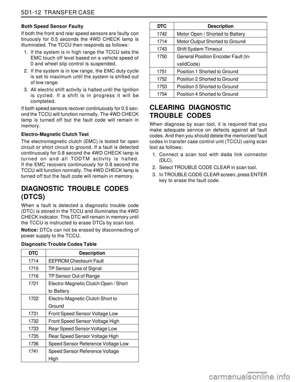
Diagnostic Trouble Codes Table
CLEARING DIAGNOSTIC
TROUBLE CODES
When diagnose by scan tool, it is required that you
make adequate service on defects against all fault
codes. And then you should delete the memorized fault
codes in transfer case control unit (TCCU) using scan
tool as follows;
1. Connect a scan tool with dada link connector
(DLC).
2. Select TROUBLE CODE CLEAR in scan tool.
3. In TROUBLE CODE CLEAR screen, press ENTER
key to erase the fault code.
Description
EEPROM Checksum Fault
TP Sensor Loss of Signal
TP Sensor Out of Range
Electro-Magnetic Clutch Open / Short
to Battery
Electro-Magnetic Clutch Short to
Ground
Front Speed Sensor Voltage Low
Front Speed Sensor Voltage High
Rear Speed Sensor Voltage Low
Rear Speed Sensor Voltage High
Speed Sensor Reference Voltage Low
Speed Sensor Reference Voltage
High DTC
1714
1715
1716
1721
1722
1731
1732
1733
1735
1736
1741
Description
Motor Open / Shorted to Battery
Motor Output Shorted to Ground
Shift System Timeout
General Position Encoder Fault (In-
validCode)
Position 1 Shorted to Ground
Position 2 Shorted to Ground
Position 3 Shorted to Ground
Position 4 Shorted to Ground DTC
1742
1714
1743
1750
1751
1752
1753
1754
Page 1384 of 2053
SSANGYONG MY2002
5D1-14 TRANSFER CASE
4WD CHECK INDICATOR STAYS ON WITH IGNITION SWITCH ON
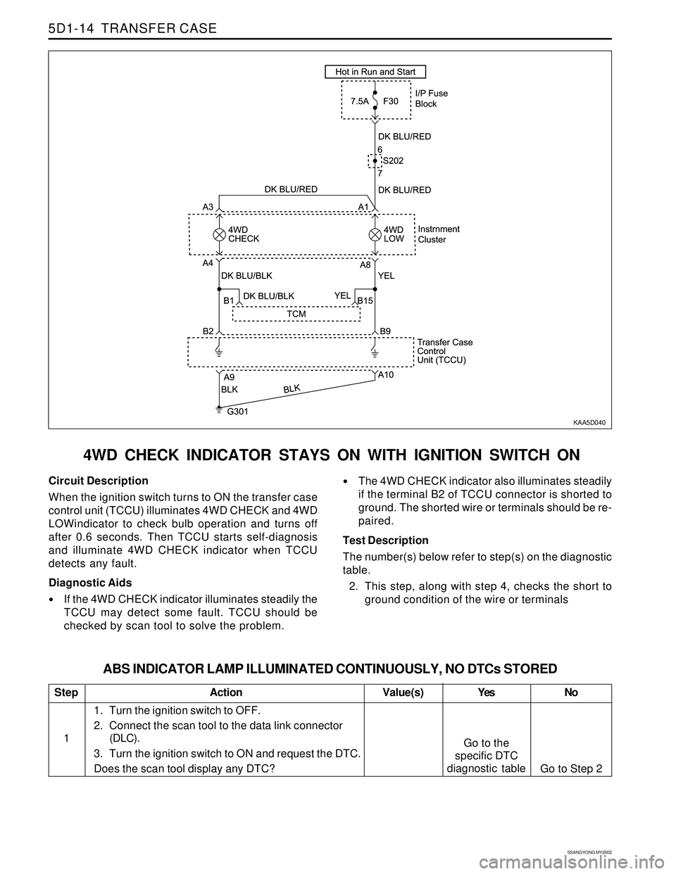
KAA5D040
Circuit Description
When the ignition switch turns to ON the transfer case
control unit (TCCU) illuminates 4WD CHECK and 4WD
LOWindicator to check bulb operation and turns off
after 0.6 seconds. Then TCCU starts self-diagnosis
and illuminate 4WD CHECK indicator when TCCU
detects any fault.
Diagnostic Aids
If the 4WD CHECK indicator illuminates steadily the
TCCU may detect some fault. TCCU should be
checked by scan tool to solve the problem.
The 4WD CHECK indicator also illuminates steadily
if the terminal B2 of TCCU connector is shorted to
ground. The shorted wire or terminals should be re-
paired.
Test Description
The number(s) below refer to step(s) on the diagnostic
table.
2. This step, along with step 4, checks the short to
ground condition of the wire or terminals
Step
1
ABS INDICATOR LAMP ILLUMINATED CONTINUOUSLY, NO DTCs STORED
Action Yes
Go to the
specific DTC
diagnostic tableNo
Go to Step 2 Value(s)
1. Turn the ignition switch to OFF.
2. Connect the scan tool to the data link connector
(DLC).
3. Turn the ignition switch to ON and request the DTC.
Does the scan tool display any DTC?
Page 1385 of 2053
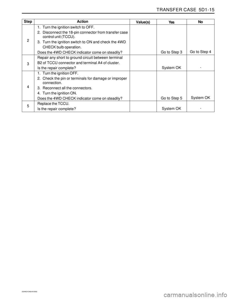
TRANSFER CASE 5D1-15
SSANGYONG MY2002
Step
2
3
4
5Action
Yes
Go to Step 3
System OK
Go to Step 5
System OKNo
Go to Step 4
-
System OK
- Value(s)
1. Turn the ignition switch to OFF.
2. Disconnect the 18-pin connector from transfer case
control unit (TCCU).
3. Turn the ignition switch to ON and check the 4WD
CHECK bulb operation.
Does the 4WD CHECK indicator come on steadily?
Repair any short to ground circuit between terminal
B2 of TCCU connector and terminal A4 of cluster.
Is the repair complete?
1. Turn the ignition OFF.
2. Check the pin or terminals for damage or improper
connection.
3. Reconnect all the connectors.
4. Turn the ignition ON.
Does the 4WD CHECK indicator come on steadily?
Replace the TCCU.
Is the repair complete?
Page 1386 of 2053
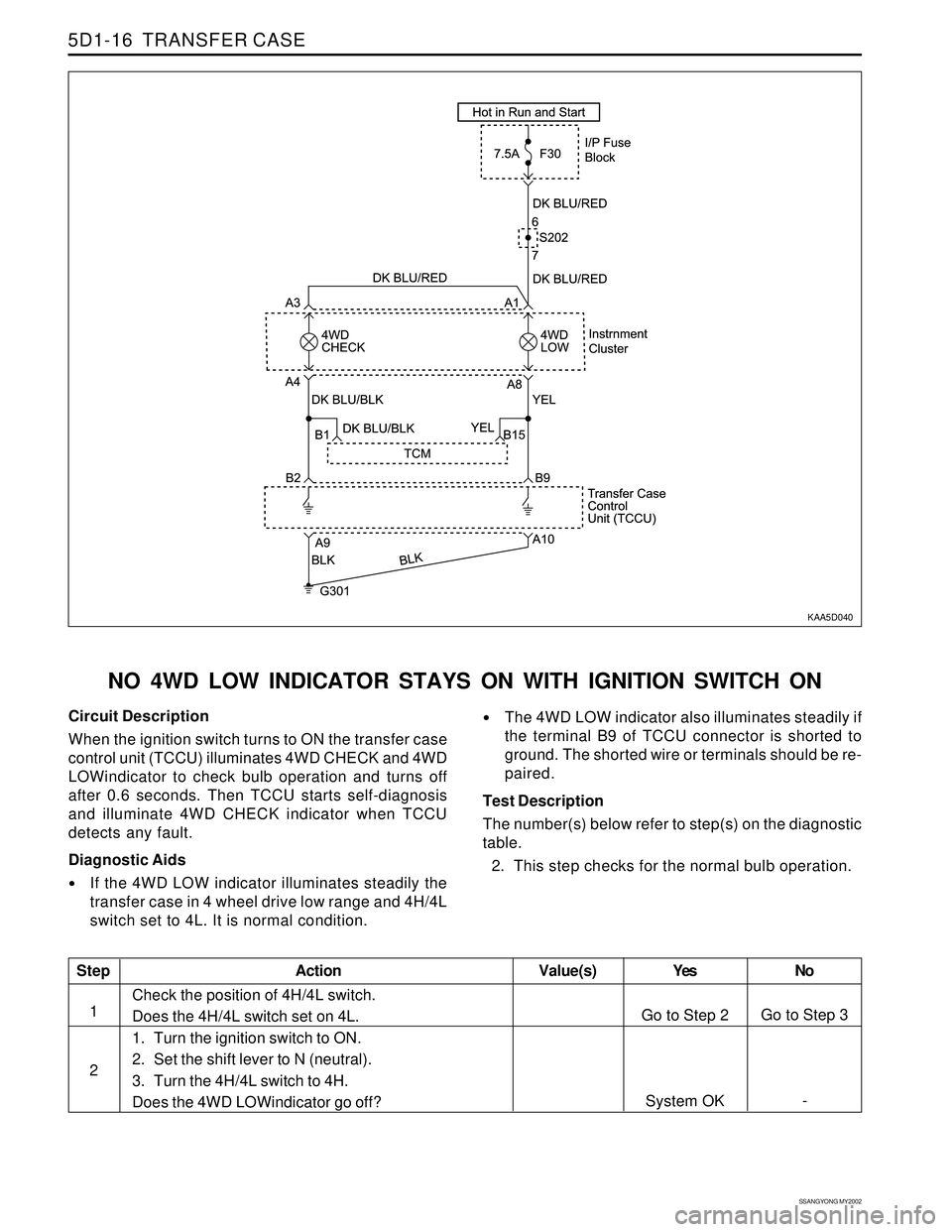
SSANGYONG MY2002
5D1-16 TRANSFER CASE
KAA5D040
NO 4WD LOW INDICATOR STAYS ON WITH IGNITION SWITCH ON
Circuit Description
When the ignition switch turns to ON the transfer case
control unit (TCCU) illuminates 4WD CHECK and 4WD
LOWindicator to check bulb operation and turns off
after 0.6 seconds. Then TCCU starts self-diagnosis
and illuminate 4WD CHECK indicator when TCCU
detects any fault.
Diagnostic Aids
If the 4WD LOW indicator illuminates steadily the
transfer case in 4 wheel drive low range and 4H/4L
switch set to 4L. It is normal condition.
The 4WD LOW indicator also illuminates steadily if
the terminal B9 of TCCU connector is shorted to
ground. The shorted wire or terminals should be re-
paired.
Test Description
The number(s) below refer to step(s) on the diagnostic
table.
2. This step checks for the normal bulb operation.
Step
1
2
Action Yes
Go to Step 2
System OKNo
Go to Step 3
- Value(s)
Check the position of 4H/4L switch.
Does the 4H/4L switch set on 4L.
1. Turn the ignition switch to ON.
2. Set the shift lever to N (neutral).
3. Turn the 4H/4L switch to 4H.
Does the 4WD LOWindicator go off?
Page 1387 of 2053
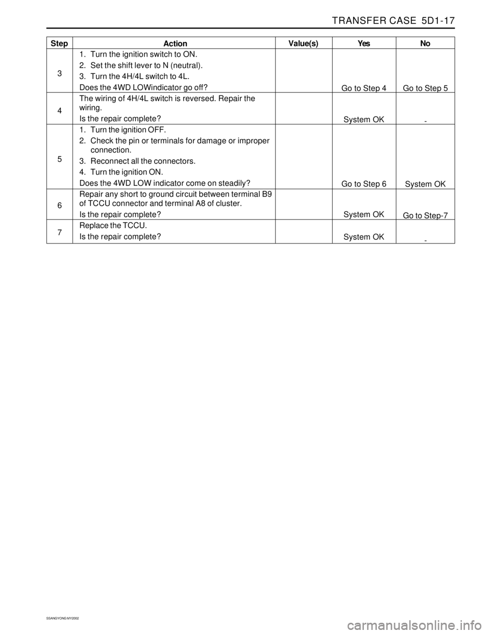
TRANSFER CASE 5D1-17
SSANGYONG MY2002
Step
3
4
5
6
7ActionYes
Go to Step 4
System OK
Go to Step 6
System OK
System OKNo
Go to Step 5
-
System OK
Go to Step-7
- Value(s)
1. Turn the ignition switch to ON.
2. Set the shift lever to N (neutral).
3. Turn the 4H/4L switch to 4L.
Does the 4WD LOWindicator go off?
The wiring of 4H/4L switch is reversed. Repair the
wiring.
Is the repair complete?
1. Turn the ignition OFF.
2. Check the pin or terminals for damage or improper
connection.
3. Reconnect all the connectors.
4. Turn the ignition ON.
Does the 4WD LOW indicator come on steadily?
Repair any short to ground circuit between terminal B9
of TCCU connector and terminal A8 of cluster.
Is the repair complete?
Replace the TCCU.
Is the repair complete?
Page 1389 of 2053
TRANSFER CASE 5D1-67
SSANGYONG MY2002
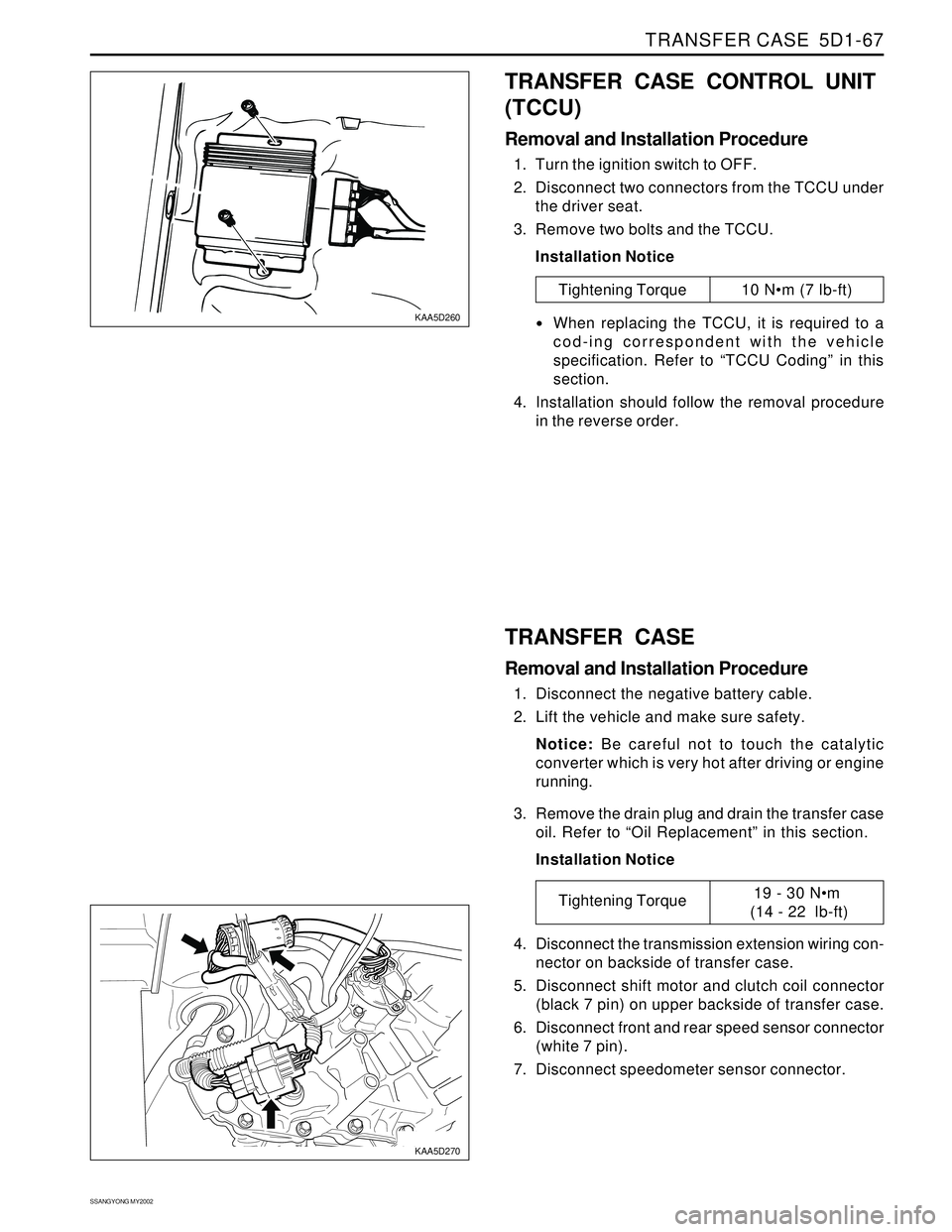
KAA5D260
KAA5D270
TRANSFER CASE CONTROL UNIT
(TCCU)
Removal and Installation Procedure
1. Turn the ignition switch to OFF.
2. Disconnect two connectors from the TCCU under
the driver seat.
3. Remove two bolts and the TCCU.
Installation Notice
Tightening Torque 10 Nm (7 lb-ft)
When replacing the TCCU, it is required to a
cod-ing correspondent with the vehicle
specification. Refer to “TCCU Coding” in this
section.
4. Installation should follow the removal procedure
in the reverse order.
TRANSFER CASE
Removal and Installation Procedure
1. Disconnect the negative battery cable.
2. Lift the vehicle and make sure safety.
Notice: Be careful not to touch the catalytic
converter which is very hot after driving or engine
running.
3. Remove the drain plug and drain the transfer case
oil. Refer to “Oil Replacement” in this section.
Installation Notice
4. Disconnect the transmission extension wiring con-
nector on backside of transfer case.
5. Disconnect shift motor and clutch coil connector
(black 7 pin) on upper backside of transfer case.
6. Disconnect front and rear speed sensor connector
(white 7 pin).
7. Disconnect speedometer sensor connector.
Tightening Torque19 - 30 Nm
(14 - 22 lb-ft)