1997 SSANGYONG KORANDO ignition
[x] Cancel search: ignitionPage 1250 of 2053
5A-152 AUTOMATIC TRANSMISSION
SSANGYONG MY2002
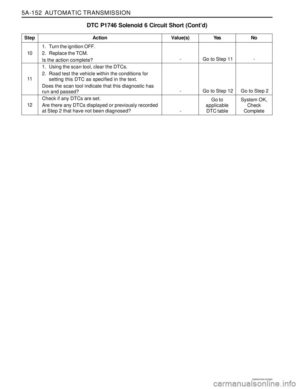
DTC P1746 Solenoid 6 Circuit Short (Cont’d)
1. Turn the ignition OFF.
2. Replace the TCM.
Is the action complete?
1. Using the scan tool, clear the DTCs.
2. Road test the vehicle within the conditions for
setting this DTC as specified in the text.
Does the scan tool indicate that this diagnostic has
run and passed?
Check if any DTCs are set.
Are there any DTCs displayed or previously recorded
at Step 2 that have not been diagnosed?
StepAction Value(s) Yes No
10
- Go to Step 11 -
- Go to Step 12 Go to Step 2 11
12
-Go to
applicable
DTC tableSystem OK,
Check
Complete
Page 1252 of 2053
5A-154 AUTOMATIC TRANSMISSION
SSANGYONG MY2002
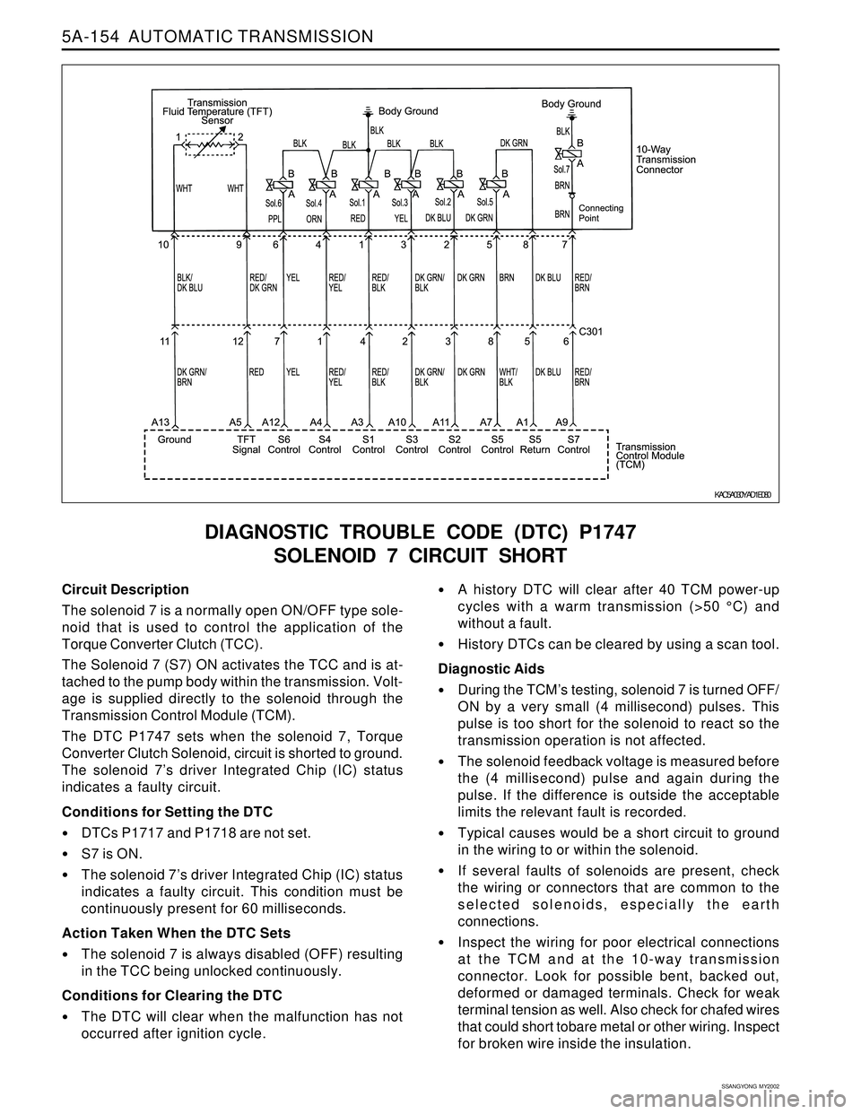
DIAGNOSTIC TROUBLE CODE (DTC) P1747
SOLENOID 7 CIRCUIT SHORT
Circuit Description
The solenoid 7 is a normally open ON/OFF type sole-
noid that is used to control the application of the
Torque Converter Clutch (TCC).
The Solenoid 7 (S7) ON activates the TCC and is at-
tached to the pump body within the transmission. Volt-
age is supplied directly to the solenoid through the
Transmission Control Module (TCM).
The DTC P1747 sets when the solenoid 7, Torque
Converter Clutch Solenoid, circuit is shorted to ground.
The solenoid 7’s driver Integrated Chip (IC) status
indicates a faulty circuit.
Conditions for Setting the DTC
DTCs P1717 and P1718 are not set.
S7 is ON.
The solenoid 7’s driver Integrated Chip (IC) status
indicates a faulty circuit. This condition must be
continuously present for 60 milliseconds.
Action Taken When the DTC Sets
The solenoid 7 is always disabled (OFF) resulting
in the TCC being unlocked continuously.
Conditions for Clearing the DTC
The DTC will clear when the malfunction has not
occurred after ignition cycle.
A history DTC will clear after 40 TCM power-up
cycles with a warm transmission (>50 °C) and
without a fault.
History DTCs can be cleared by using a scan tool.
Diagnostic Aids
During the TCM’s testing, solenoid 7 is turned OFF/
ON by a very small (4 millisecond) pulses. This
pulse is too short for the solenoid to react so the
transmission operation is not affected.
The solenoid feedback voltage is measured before
the (4 millisecond) pulse and again during the
pulse. If the difference is outside the acceptable
limits the relevant fault is recorded.
Typical causes would be a short circuit to ground
in the wiring to or within the solenoid.
If several faults of solenoids are present, check
the wiring or connectors that are common to the
selected solenoids, especially the earth
connections.
Inspect the wiring for poor electrical connections
at the TCM and at the 10-way transmission
connector. Look for possible bent, backed out,
deformed or damaged terminals. Check for weak
terminal tension as well. Also check for chafed wires
that could short tobare metal or other wiring. Inspect
for broken wire inside the insulation.
KAC5A030YAD1E080
Page 1253 of 2053
AUTOMATIC TRANSMISSION 5A-155
SSANGYONG MY2002
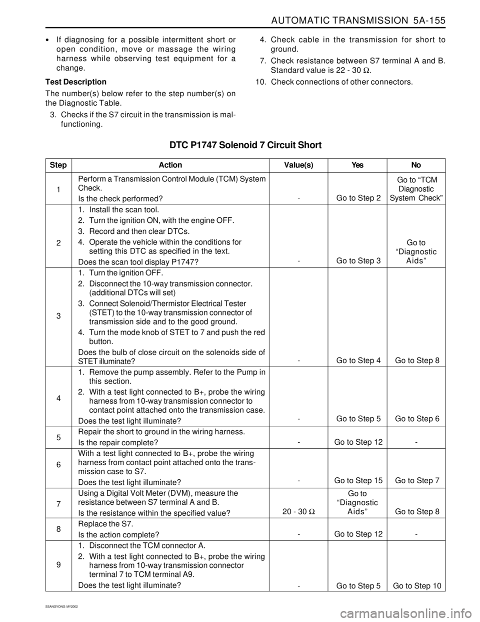
DTC P1747 Solenoid 7 Circuit Short
If diagnosing for a possible intermittent short or
open condition, move or massage the wiring
harness while observing test equipment for a
change.
Test Description
The number(s) below refer to the step number(s) on
the Diagnostic Table.
3. Checks if the S7 circuit in the transmission is mal-
functioning.4. Check cable in the transmission for short to
ground.
7. Check resistance between S7 terminal A and B.
Standard value is 22 - 30 Ω.
10. Check connections of other connectors.
- Go to Step 15 Go to Step 7 1Perform a Transmission Control Module (TCM) System
Check.
Is the check performed?
1. Install the scan tool.
2. Turn the ignition ON, with the engine OFF.
3. Record and then clear DTCs.
4. Operate the vehicle within the conditions for
setting this DTC as specified in the text.
Does the scan tool display P1747?
1. Turn the ignition OFF.
2. Disconnect the 10-way transmission connector.
(additional DTCs will set)
3. Connect Solenoid/Thermistor Electrical Tester
(STET) to the 10-way transmission connector of
transmission side and to the good ground.
4. Turn the mode knob of STET to 7 and push the red
button.
Does the bulb of close circuit on the solenoids side of
STET illuminate?
1. Remove the pump assembly. Refer to the Pump in
this section.
2. With a test light connected to B+, probe the wiring
harness from 10-way transmission connector to
contact point attached onto the transmission case.
Does the test light illuminate?
Repair the short to ground in the wiring harness.
Is the repair complete?
With a test light connected to B+, probe the wiring
harness from contact point attached onto the trans-
mission case to S7.
Does the test light illuminate?
Using a Digital Volt Meter (DVM), measure the
resistance between S7 terminal A and B.
Is the resistance within the specified value?
Replace the S7.
Is the action complete?
1. Disconnect the TCM connector A.
2. With a test light connected to B+, probe the wiring
harness from 10-way transmission connector
terminal 7 to TCM terminal A9.
Does the test light illuminate?
StepAction Value(s) Yes No
2
3
-
Go to Step 2 Go to “TCM
Diagnostic
System Check”
- Go to Step 4 Go to Step 8
5
6 4
- Go to Step 5 Go to Step 6
- Go to Step 12 -
7
8
9
- Go to Step 12 -
- Go to Step 5 Go to Step 10
- Go to Step 3Go to
“Diagnostic
Aids”
20 - 30 ΩGo to
“Diagnostic
Aids”
Go to Step 8
Page 1254 of 2053
5A-156 AUTOMATIC TRANSMISSION
SSANGYONG MY2002
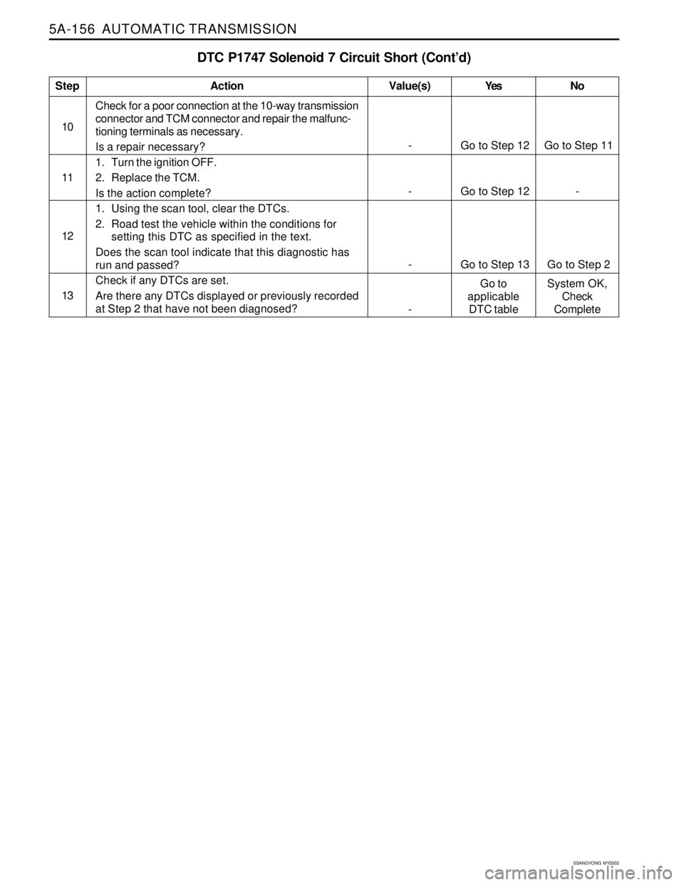
DTC P1747 Solenoid 7 Circuit Short (Cont’d)
Check for a poor connection at the 10-way transmission
connector and TCM connector and repair the malfunc-
tioning terminals as necessary.
Is a repair necessary?
1. Turn the ignition OFF.
2. Replace the TCM.
Is the action complete?
1. Using the scan tool, clear the DTCs.
2. Road test the vehicle within the conditions for
setting this DTC as specified in the text.
Does the scan tool indicate that this diagnostic has
run and passed?
Check if any DTCs are set.
Are there any DTCs displayed or previously recorded
at Step 2 that have not been diagnosed?
StepAction Value(s) Yes No
10
- Go to Step 12 Go to Step 11
13 11
- Go to Step 12 -
12
- Go to Step 13 Go to Step 2
-Go to
applicable
DTC tableSystem OK,
Check
Complete
Page 1357 of 2053
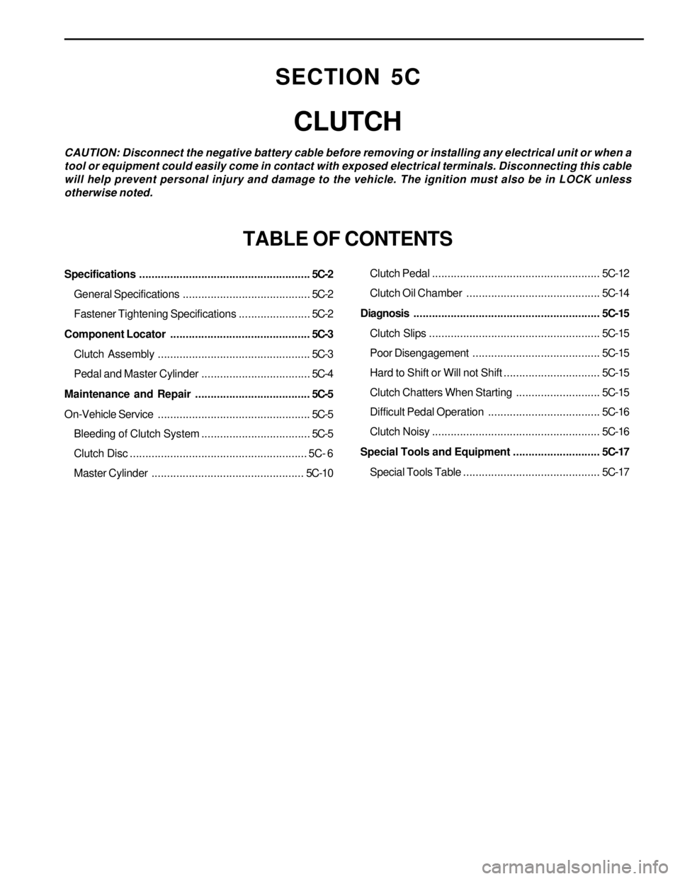
Specifications.......................................................5C-2
General Specifications.........................................5C-2
Fastener Tightening Specifications.......................5C-2
Component Locator.............................................5C-3
Clutch Assembly.................................................5C-3
Pedal and Master Cylinder...................................5C-4
Maintenance and Repair.....................................5C-5
On-Vehicle Service.................................................5C-5
Bleeding of Clutch System...................................5C-5
Clutch Disc......................................................... 5C- 6
Master Cylinder.................................................5C-10Clutch Pedal...................................................... 5C-12
Clutch Oil Chamber........................................... 5C-14
Diagnosis............................................................ 5C-15
Clutch Slips....................................................... 5C-15
Poor Disengagement ......................................... 5C-15
Hard to Shift or Will not Shift............................... 5C-15
Clutch Chatters When Starting........................... 5C-15
Difficult Pedal Operation.................................... 5C-16
Clutch Noisy...................................................... 5C-16
Special Tools and Equipment............................ 5C-17
Special Tools Table............................................ 5C-17
SECTION 5C
CLUTCH
CAUTION: Disconnect the negative battery cable before removing or installing any electrical unit or when a
tool or equipment could easily come in contact with exposed electrical terminals. Disconnecting this cable
will help prevent personal injury and damage to the vehicle. The ignition must also be in LOCK unless
otherwise noted.
TABLE OF CONTENTS
Page 1372 of 2053
SECTION 5D1
TRANSFER CASE (TOD)
CAUTION: Disconnect the negative battery cable before removing or installing any electrical unit or when a
tool or equipment could easily come in contact with exposed electrical terminals. Disconnecting this cable
will help prevent personal injury and damage to the vehicle. The ignition must also be in LOCK unless
other-wise noted.
TABLE OF CONTENTS
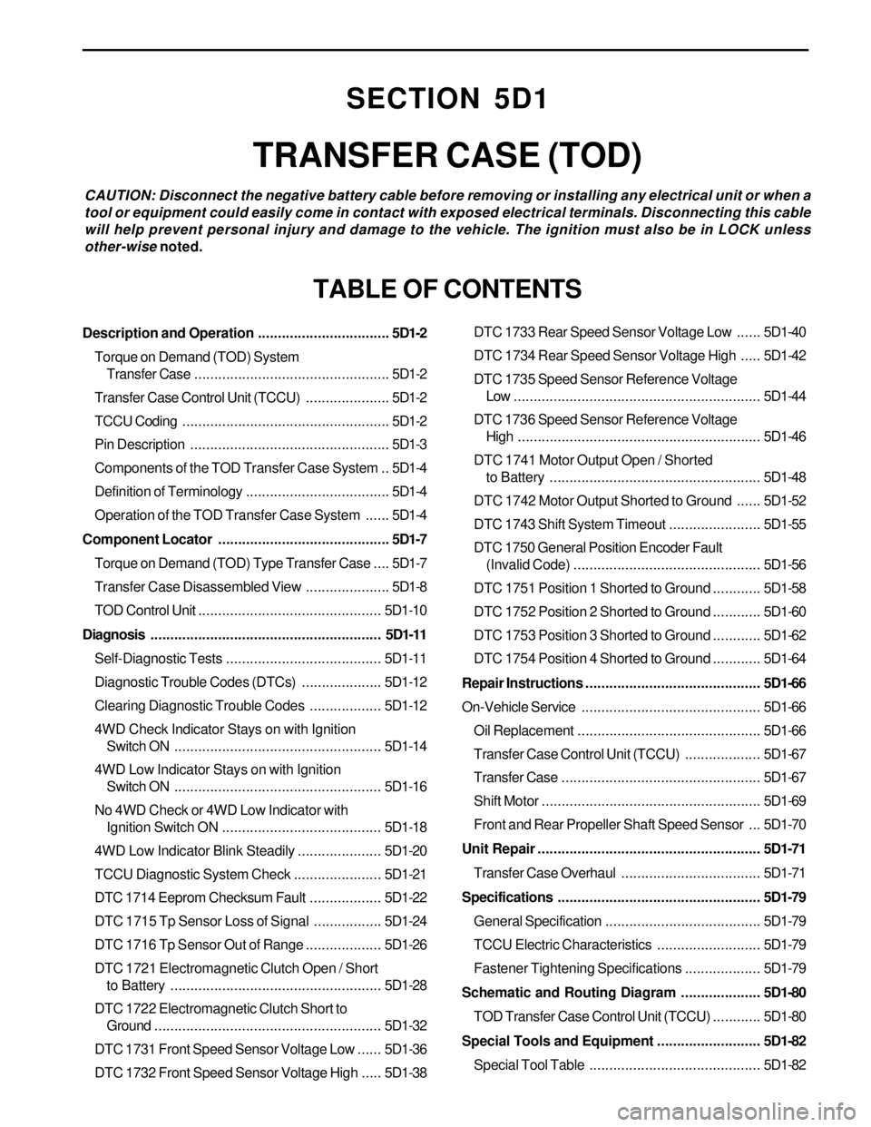
Description and Operation.................................5D1-2
Torque on Demand (TOD) System
Transfer Case.................................................5D1-2
Transfer Case Control Unit (TCCU).....................5D1-2
TCCU Coding....................................................5D1-2
Pin Description..................................................5D1-3
Components of the TOD Transfer Case System ..5D1-4
Definition of Terminology....................................5D1-4
Operation of the TOD Transfer Case System......5D1-4
Component Locator...........................................5D1-7
Torque on Demand (TOD) Type Transfer Case....5D1-7
Transfer Case Disassembled View.....................5D1-8
TOD Control Unit..............................................5D1-10
Diagnosis..........................................................5D1-11
Self-Diagnostic Tests.......................................5D1-11
Diagnostic Trouble Codes (DTCs)....................5D1-12
Clearing Diagnostic Trouble Codes..................5D1-12
4WD Check Indicator Stays on with Ignition
Switch ON....................................................5D1-14
4WD Low Indicator Stays on with Ignition
Switch ON....................................................5D1-16
No 4WD Check or 4WD Low Indicator with
Ignition Switch ON........................................5D1-18
4WD Low Indicator Blink Steadily.....................5D1-20
TCCU Diagnostic System Check......................5D1-21
DTC 1714 Eeprom Checksum Fault..................5D1-22
DTC 1715 Tp Sensor Loss of Signal.................5D1-24
DTC 1716 Tp Sensor Out of Range...................5D1-26
DTC 1721 Electromagnetic Clutch Open / Short
to Battery.....................................................5D1-28
DTC 1722 Electromagnetic Clutch Short to
Ground.........................................................5D1-32
DTC 1731 Front Speed Sensor Voltage Low......5D1-36
DTC 1732 Front Speed Sensor Voltage High.....5D1-38DTC 1733 Rear Speed Sensor Voltage Low......5D1-40
DTC 1734 Rear Speed Sensor Voltage High.....5D1-42
DTC 1735 Speed Sensor Reference Voltage
Low ..............................................................5D1-44
DTC 1736 Speed Sensor Reference Voltage
High.............................................................5D1-46
DTC 1741 Motor Output Open / Shorted
to Battery.....................................................5D1-48
DTC 1742 Motor Output Shorted to Ground......5D1-52
DTC 1743 Shift System Timeout.......................5D1-55
DTC 1750 General Position Encoder Fault
(Invalid Code)...............................................5D1-56
DTC 1751 Position 1 Shorted to Ground............5D1-58
DTC 1752 Position 2 Shorted to Ground............5D1-60
DTC 1753 Position 3 Shorted to Ground............5D1-62
DTC 1754 Position 4 Shorted to Ground............5D1-64
Repair Instructions............................................5D1-66
On-Vehicle Service.............................................5D1-66
Oil Replacement..............................................5D1-66
Transfer Case Control Unit (TCCU)...................5D1-67
Transfer Case..................................................5D1-67
Shift Motor.......................................................5D1-69
Front and Rear Propeller Shaft Speed Sensor ...5D1-70
Unit Repair........................................................5D1-71
Transfer Case Overhaul...................................5D1-71
Specifications...................................................5D1-79
General Specification.......................................5D1-79
TCCU Electric Characteristics..........................5D1-79
Fastener Tightening Specifications...................5D1-79
Schematic and Routing Diagram....................5D1-80
TOD Transfer Case Control Unit (TCCU)............5D1-80
Special Tools and Equipment..........................5D1-82
Special Tool Table ...........................................5D1-82
Page 1373 of 2053
TRANSFER CASE 5D1-3
SSANGYONG MY2002
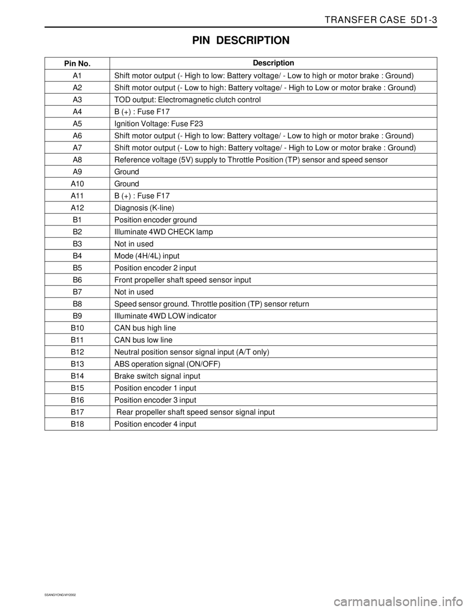
A1
A2
A3
A4
A5
A6
A7
A8
A9
A10
A11
A12
B1
B2
B3
B4
B5
B6
B7
B8
B9
B10
B11
B12
B13
B14
B15
B16
B17
B18Shift motor output (- High to low: Battery voltage/ - Low to high or motor brake : Ground)
Shift motor output (- Low to high: Battery voltage/ - High to Low or motor brake : Ground)
TOD output: Electromagnetic clutch control
B (+) : Fuse F17
Ignition Voltage: Fuse F23
Shift motor output (- High to low: Battery voltage/ - Low to high or motor brake : Ground)
Shift motor output (- Low to high: Battery voltage/ - High to Low or motor brake : Ground)
Reference voltage (5V) supply to Throttle Position (TP) sensor and speed sensor
Ground
Ground
B (+) : Fuse F17
Diagnosis (K-line)
Position encoder ground
Illuminate 4WD CHECK lamp
Not in used
Mode (4H/4L) input
Position encoder 2 input
Front propeller shaft speed sensor input
Not in used
Speed sensor ground. Throttle position (TP) sensor return
Illuminate 4WD LOW indicator
CAN bus high line
CAN bus low line
Neutral position sensor signal input (A/T only)
ABS operation signal (ON/OFF)
Brake switch signal input
Position encoder 1 input
Position encoder 3 input
Rear propeller shaft speed sensor signal input
Position encoder 4 input
PIN DESCRIPTION
Pin No.Description
Page 1374 of 2053
SSANGYONG MY2002
5D1-4 TRANSFER CASE
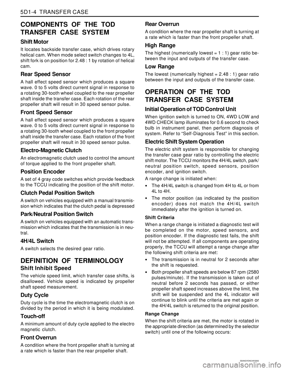
COMPONENTS OF THE TOD
TRANSFER CASE SYSTEM
Shift Motor
It locates backside transfer case, which drives rotary
helical cam. When mode select switch changes to 4L,
shift fork is on position for 2.48 : 1 by rotation of helical
cam.
Rear Speed Sensor
A hall effect speed sensor which produces a square
wave. 0 to 5 volts direct current signal in response to
a rotating 30-tooth wheel coupled to the rear propeller
shaft inside the transfer case. Each rotation of the rear
propeller shaft will result in 30 speed sensor pulse.
Front Speed Sensor
A hall effect speed sensor which produces a square
wave. 0 to 5 volts direct current signal in response to
a rotating 30-tooth wheel coupled to the front propeller
shaft inside the transfer case. Each rotation of the front
propeller shaft will result in 30 speed sensor pulse.
Electro-Magnetic Clutch
An electromagnetic clutch used to control the amount
of torque applied to the front propeller shaft.
Position Encoder
A set of 4 gray code switches which provide feedback
to the TCCU indicating the position of the shift motor.
Clutch Pedal Position Switch
A switch on vehicles equipped with a manual transmis-
sion which indicates that the clutch pedal is depressed
Park/Neutral Position Switch
A switch on vehicles equipped with an automatic trans-
mission which indicates that the transmission is in neu-
tral.
4H/4L Switch
A switch selects the desired gear ratio.
DEFINITION OF TERMINOLOGY
Shift Inhibit Speed
The vehicle speed limit, which transfer case shifts, is
disallowed. Vehicle speed is indicated by propeller
shaft speed measurement.
Duty Cycle
Duty cycle is the time the electromagnetic clutch is on
divided by the period in which it is being modulated.
Touch-off
A minimum amount of duty cycle applied to the electro
magnetic clutch.
Front Overrun
A condition where the front propeller shaft is turning at
a rate which is faster than the rear propeller shaft.
Rear Overrun
A condition where the rear propeller shaft is turning at
a rate which is faster than the front propeller shaft.
High Range
The highest (numerically lowest = 1 : 1) gear ratio be-
tween the input and outputs of the transfer case.
Low Range
The lowest (numerically highest = 2.48 : 1) gear ratio
between the input and outputs of the transfer case.
OPERATION OF THE TOD
TRANSFER CASE SYSTEM
Initial Operation of TOD Control Unit
When ignition switch is turned to ON, 4WD LOW and
4WD CHECK lamp illuminates for 0.6 second to check
bulb in instrument panel, then perform diagnosis of
system. Refer to “Self-Diagnosis Test” in this section.
Electric Shift System Operation
The electric shift system is responsible for changing
the transfer case gear ratio by controlling the electric
shift motor. The TCCU monitors the 4H/4L switch, park/
neutral position switch, speed sensors, position
encoder, and ignition switch.
A range change is initiated when:
The 4H/4L switch is changed from 4H to 4L or from
4L to 4H.
The motor position (as indicated by the position
encoder) does not match the 4H/4L switch
immediately after the ignition is turned on.
Shift Criteria
When a range change is initiated a diagnostic test will
be completed on the motor, speed sensors, and
position encoder. If the diagnostic test fails, the shift
will not be attempted. If all components are operating
properly, the TCCU will attempt a range change after
the following shift criteria are met:
The transmission is in neutral for 2 seconds after
the shift is requested.
Both propeller shaft speeds are below 87 rpm (2580
pulses/minute). If the transmission is taken out of
neutral before 2 seconds has passed, or either
propeller shaft speed increases above the limit, the
shift will be suspended and the 4L indicator will
continue to blink until the criteria are met again or
the 4H/4L switch is returned to the original position.
Range Change
When the shift criteria are met, the motor is rotated in
the appropriate direction (as determined by the selector
switch) until one of the following occurs: