Page 1515 of 2053

SSANGYONG MY2002
7A-14 HEATING AND VENTILATION SYSTEM
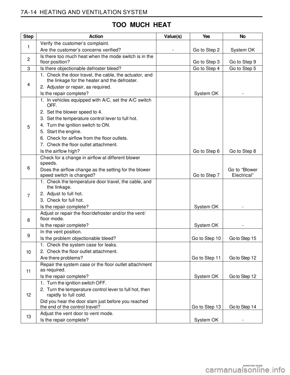
TOO MUCH HEAT
Step
1
2
3
4
5
6
7
8
9
10
11
12
13Action
Verify the customer’s complaint.
Are the customer’s concerns verified?
Is there too much heat when the mode switch is in the
floor position?
Is there objectionable defroster bleed?
1. Check the door travel, the cable, the actuator, and
the linkage for the heater and the defroster.
2. Adjuster or repair, as required.
Is the repair complete?
1. In vehicles equipped with A/C, set the A/C switch
OFF.
2. Set the blower speed to 4.
3. Set the temperature control lever to full hot.
4. Turn the ignition switch to ON.
5. Start the engine.
6. Check for airflow from the floor outlets.
7. Check the floor outlet attachment.
Is the airflow high?
Check for a change in airflow at different blower
speeds.
Does the airflow change as the setting for the blower
speed switch is changed?
1. Check the temperature door travel, the cable, and
the linkage.
2. Adjust to full hot.
3. Check for full hot.
Is the repair complete?
Adjust or repair the floor/defroster and/or the vent/
floor mode.
Is the repair complete?
In the vent position.
Is the problem objectionable bleed?
1. Check the system case for leaks.
2. Check the floor outlet attachment.
Are there problems?
Repair the system case or the floor outlet attachment
as required.
Is the repair complete?
1. Turn the ignition switch OFF.
2. Turn the temperature control lever to full hot, then
rapidly to full cold.
Did you hear the door slam just before you reached
the end of the control travel?
Adjust the vent door to vent mode.
Is the repair complete?Yes
Go to Step 2
Go to Step 3
Go to Step 4
System OK
Go to Step 6
Go to Step 7
System OK
System OK
Go to Step 10
Go to Step 11
System OK
Go to Step 13
System OKNo
System OK
Go to Step 9
Go to Step 5
-
Go to Step 8
Go to “Blower
Electrical”
-
-
Go to Step 15
Go to Step 12
Go to Step 12
Go to Step 14
-Value(s)
-
Page 1517 of 2053

SSANGYONG MY2002
7A-16 HEATING AND VENTILATION SYSTEM
BLOWER NOISE
Step
1
2
3
4
5
6
7
8
9
10
11
12
13
14Action
Verify the customer’s complaint.
Are the customer’s concerns verified?
1. Sit inside the vehicle.
2. Close the doors and windows.
3. Turn the ignition ON.
4. Start the engine.
5. Set the temperature to full cold.
6. Cycle through the blower speeds, the modes, and
the temperature settings in order to find the noise.
Is the blower noise constant at high blower speeds or
in other modes?
Check for vibrations from the blower motor and fan
assembly at each blower speed by feeling the blower
motor housing.
Did you find excessive vibration?
1. Remove the blower motor and fan assembly.
Refer to “Blower Motor” in this section.
2. Check for foreign materials at the opening of the
blower inlet.
Did you find any foreign materials at the blower inlet?
Remove all foreign materials.
Is the repair complete?
1. Examine the blower fan for wear spots, cracked
blades, a cracked hub, a loose fan retaining nuts,
or bad alignment.
2. Examine the blower case for sports.
Did you find any problem?
Repair as required.
Is the repair complete?
Replace the motor and fan assembly.
Is the repair complete?
If the noise is a click/tick or whine, replace the motor.
Is the repair complete?
Reinstall the original motor.
Is the problem still present?
1. Set the blower speed on 4.
2. Check full hot to full cold temperature positions in
the defroster, floor, and vent modes.
Is the noise present in the defrost mode only?
1. Check the ducts for obstructions for foreign
materials.
2. Remove any obstructions or foreign materials.
3. Check floor /defroster door seals.
4. Repair or replace as needed.
Is the repair complete?
Is the noise present in the floor mode only?
Is the noise present in the vent mode only?Yes
Go to Step 2
Go to Step 11
Go to Step 6
Go to Step 5
System OK
Go to Step 7
System OK
System OK
System OK
Go to Step 11
Go to Step 12
System OK
Go to Step 12
Go to Step 15No
System OK
Go to Step 3
Go to Step 4
Go to Step 6
Go to Step 6
Go to Step 9
Go to Step 8
Go to Step 9
Go to Step 10
System OK
Go to Step 14
-
Go to Step 14
Go to Step 16Value(s)
-
Page 1530 of 2053

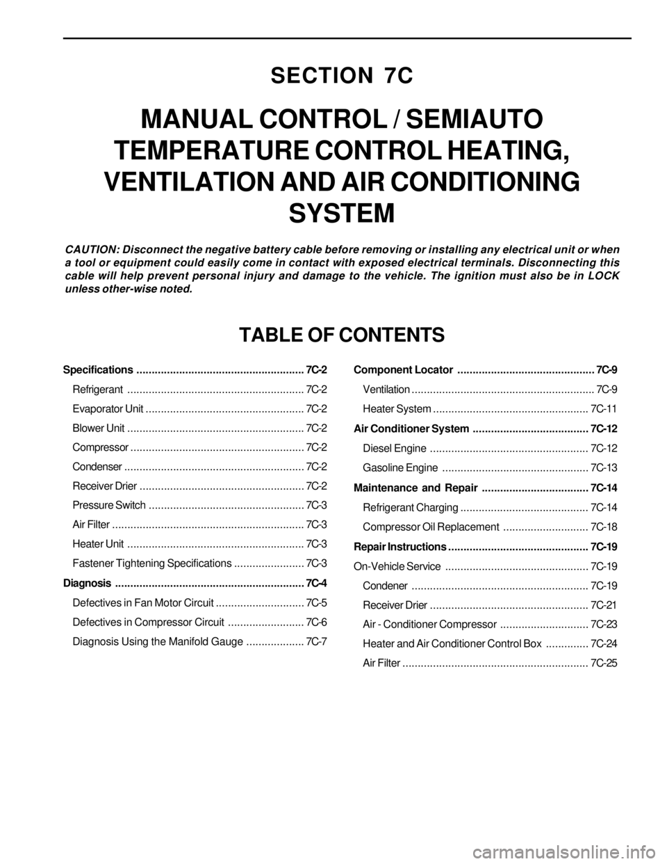
SECTION 7C
MANUAL CONTROL / SEMIAUTO
TEMPERATURE CONTROL HEATING,
VENTILATION AND AIR CONDITIONING
SYSTEM
CAUTION: Disconnect the negative battery cable before removing or installing any electrical unit or when
a tool or equipment could easily come in contact with exposed electrical terminals. Disconnecting this
cable will help prevent personal injury and damage to the vehicle. The ignition must also be in LOCK
unless other-wise noted.
TABLE OF CONTENTS
Specifications.......................................................7C-2
Refrigerant..........................................................7C-2
Evaporator Unit....................................................7C-2
Blower Unit..........................................................7C-2
Compressor.........................................................7C-2
Condenser...........................................................7C-2
Receiver Drier......................................................7C-2
Pressure Switch...................................................7C-3
Air Filter...............................................................7C-3
Heater Unit..........................................................7C-3
Fastener Tightening Specifications.......................7C-3
Diagnosis..............................................................7C-4
Defectives in Fan Motor Circuit.............................7C-5
Defectives in Compressor Circuit.........................7C-6
Diagnosis Using the Manifold Gauge...................7C-7Component Locator.............................................7C-9
Ventilation............................................................7C-9
Heater System ................................................... 7C-11
Air Conditioner System...................................... 7C-12
Diesel Engine .................................................... 7C-12
Gasoline Engine................................................ 7C-13
Maintenance and Repair................................... 7C-14
Refrigerant Charging .......................................... 7C-14
Compressor Oil Replacement............................ 7C-18
Repair Instructions.............................................. 7C-19
On-Vehicle Service............................................... 7C-19
Condener.......................................................... 7C-19
Receiver Drier.................................................... 7C-21
Air - Conditioner Compressor............................. 7C-23
Heater and Air Conditioner Control Box.............. 7C-24
Air Filter............................................................. 7C-25
Page 1563 of 2053
FATC-HAVC 7D-9
SSANGYONG MY2002
KAA7D030
DIAGNOSIS
DIAGNOSIS TEST
FATC airconditioner system has self-diagnosis
function. Turn the ignition switch ON and press intake
switch more than 4 times within 2 seconds while the
AUTO switch is pressed, then it will diagnose incarsensor, ambient sensor, water temperature sensor and
temperature actuator for open/short and will display
numerical fault code on the set temperature display of
VFD.
1 AUTO Switch
2 Fresh/Recirculation Switch
3 OFF Switch4 Airconditioner Switch
5 VFD (Vaccum Fluorescent Display)
Page 1564 of 2053
SSANGYONG MY2002
7D-10 FATC-HAVC
Self-diagnosis Method
Ignition switch “ON”
Press the intake switch more than 4 times within
2 seconds while pressing the AUTO switch
Self-diagnosis will start after turning off all displays
on VFD for 2.5 seconds
Self-diagnosis items check
(continuous action)
Airconditioner control
Self-diagnosis items check
(step action)
Press AUTO Press AUTOPress OFF
Press OFF
Diagnosis Item and Fault Code
15 : coolant Sensor Open
16 : coolant Sensor Short
17 : temperature Actuator Open/Short
18 : temperature Actuator Drive Fault 00 : normal
11 : incar Sensor Open
12 : incar Sensor Short
13 : ambient Sensor Open
14 : ambient Sensor Short
Page 1569 of 2053
FATC-HAVC 7D-15
SSANGYONG MY2002
EF
80100460810
KAA7D090
KAA7D100
KAA7D110
KAA7D120
Removal & Installation Procedure
1. Turn the ignition switch to OFF position.
2. Remove two screws on the cover of shift lever box.
3. Unscrew the screw from the center panel, pull out
each switches and remove the center panel.
4. Unscrew the 6 screws and remove the audio control
panel assembly.
5. Unscrew the 4 screws and remove the
airconditioner control panel assembly.
6. Installation should follow the removal procedure
in the reverse order.
Page 1571 of 2053

FATC-HAVC 7D-17
SSANGYONG MY2002
KAA7D150
KAA7D160
KAA7D170
KAA7D180
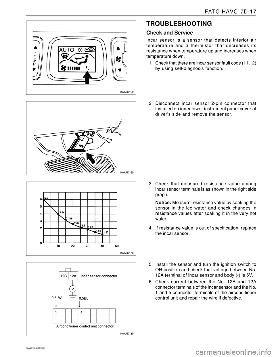
TROUBLESHOOTING
Check and Service
Incar sensor is a sensor that detects interior air
temperature and a thermistor that decreases its
resistance when temperature up and increases when
temperature down.
1. Check that there are incar sensor fault code (11,12)
by using self-diagnosis function.
2. Disconnect incar sensor 2-pin connector that
installed on inner lower instrument panel cover of
driver’s side and remove the sensor.
3. Check that measured resistance value among
incar sensor terminals is as shown in the right side
graph.
Notice: Measure resistance value by soaking the
sensor in the ice water and check changes in
resistance values after soaking it in the very hot
water.
4. If resistance value is out of specification, replace
the incar sensor.
5. Install the sensor and turn the ignition switch to
ON position and check that voltage between No.
12A terminal of incar sensor and body (-) is 5V.
6. Check current between the No. 12B and 12A
connector terminals of the incar sensor and the No.
1 and 5 connector terminals of the airconditioner
control unit and repair the wire if defective.
Page 1572 of 2053

SSANGYONG MY2002
7D-18 FATC-HAVC
KAA7D190
KAA7D200
KAA7D210
KAA7D220
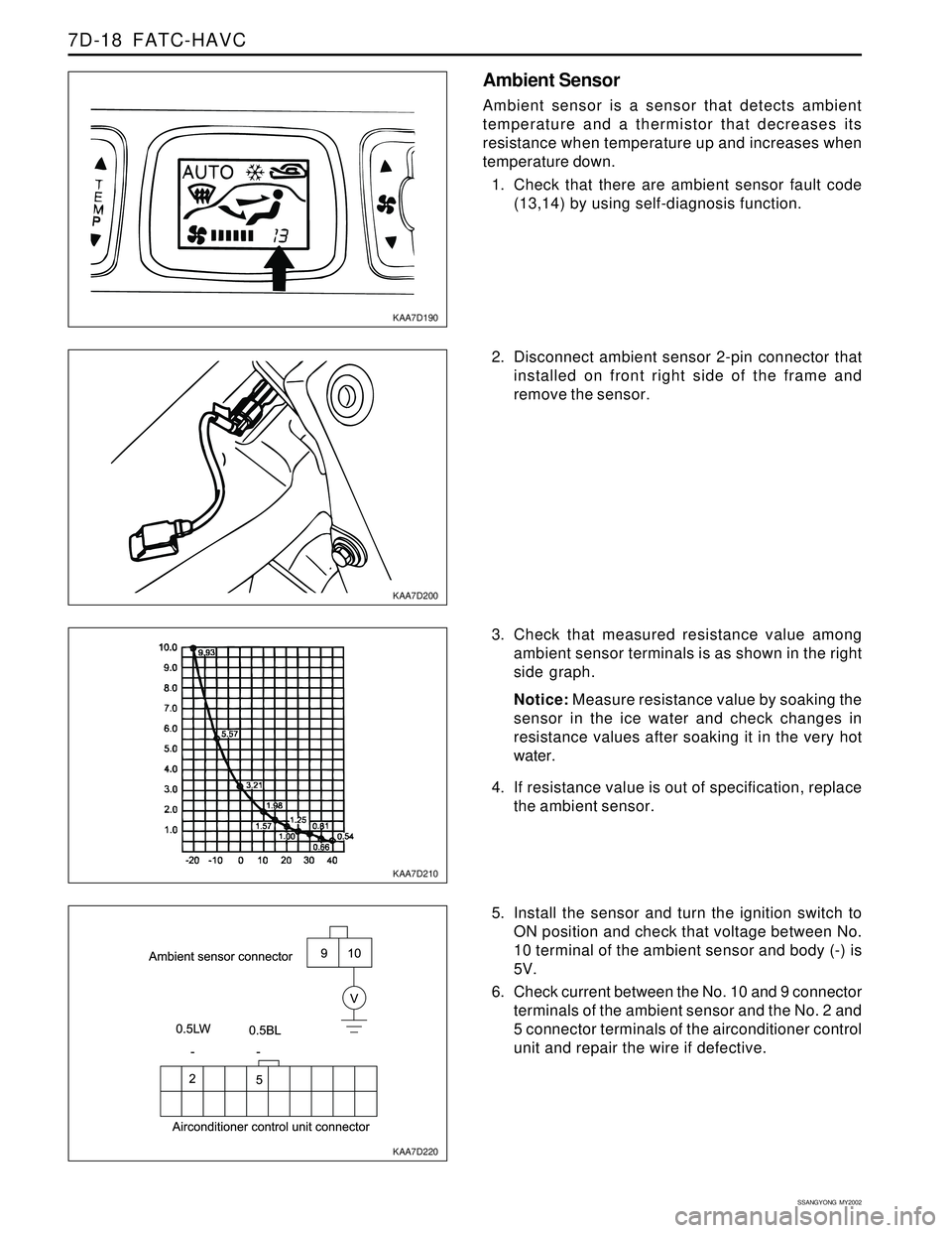
Ambient Sensor
Ambient sensor is a sensor that detects ambient
temperature and a thermistor that decreases its
resistance when temperature up and increases when
temperature down.
1. Check that there are ambient sensor fault code
(13,14) by using self-diagnosis function.
2. Disconnect ambient sensor 2-pin connector that
installed on front right side of the frame and
remove the sensor.
3. Check that measured resistance value among
ambient sensor terminals is as shown in the right
side graph.
Notice: Measure resistance value by soaking the
sensor in the ice water and check changes in
resistance values after soaking it in the very hot
water.
4. If resistance value is out of specification, replace
the ambient sensor.
5. Install the sensor and turn the ignition switch to
ON position and check that voltage between No.
10 terminal of the ambient sensor and body (-) is
5V.
6. Check current between the No. 10 and 9 connector
terminals of the ambient sensor and the No. 2 and
5 connector terminals of the airconditioner control
unit and repair the wire if defective.