Page 644 of 2053
OM600 ENGINE MECHANICAL 1B3 -- 95
D AEW OO M Y_2000
Tools Required
602 589 00 40 00 Engine Lock
Removal & Installation Procedure
1. Install the engine lock.
Engine Lock 602 589 02 40 00
2. Remove the 12-- sided stretch bolts (4).
Installation Notice
Tightening Torque45 N∙m (33 lb-ft) + 90_
Notice
If the length ’L’ of bolts exceeds 22.5mm, replace
the bolts.
3. Remove the flywheel (3), if equipped with manual
transmission.
Installation Notice
Correctly align the position of dowel pin (2).
Page 654 of 2053
OM600 ENGINE MECHANICAL 1B3 -- 105
D AEW OO M Y_2000
VALVE SPRINGS CHECK
Preceding Work : Removal of valve spring
1 Valve Spring2 Spring Scale
Service Data
OuterdiameterWirediameterFreelengthAt preloadedOuterdiameterWirediameterFreelengthLengthTension (new)Limit
33.1 mm4.20 mm50.0 mm27 mm680 -- 740 N612 N
Page 665 of 2053

1B3 -- 116 OM600 ENGINE MECHANICAL
D AEW OO M Y_2000
CHECK AND REPLACEMENT OF VALVE GUIDES
Preceding Work : Removal of cylinder head
Removal of valve spring
Removal of valve
1 Cylinder Head
2 Valve Guide3 Valve Seat Ring
a Basic Bore Diameter
Service Ddata
������������������������ �
����������������������� ������������������������
�����������������������������������
����������������������������������� �����������������������������������Item
��������������������������������������������� �
�������������������������������������������� ���������������������������������������������Outer Diameter
’D’
��������������������������������� �
�������������������������������� ���������������������������������Color Code
����������������������������������������� �
���������������������������������������� �����������������������������������������Basic Bore
Diameter ’a’
���������������������������� �
��������������������������� ����������������������������Overlap
’D’ -- ’a’
������������������������������������������ �
����������������������������������������� ������������������������������������������Valve Guide
InnerDiameter’A’
���������������������� �
��������������������� ����������������������Length
’L’
IntakeRepair size 114.251Red14.200 -- 14.2110.029 --80008030395IntakeRepair size 214.440 -- 14.451White14.400 -- 14.411
0.029--
0.0518.000 -- 8.03039.5
ExhaustRepair size 114.240 -- 14. 251Red14.200 -- 14.2110.029 --90009050377ExhaustRepair size 214.440-- 14.451White14.400 -- 14.411
0.029--
0.0519.000 -- 9.05037.7
Page 676 of 2053
OM600 ENGINE MECHANICAL 1B3 -- 127
D AEW OO M Y_2000
CHECK AND MACHINING OF VALVES
Preceding Work : Removal of cylinder head
Removal of the vale spring
Removal of the valve
I Valve Length
W Camshaft Cam Basic Diameter
X Distance (Camshaft Basic Bore -- Valve Stem)Y Half Camshaft Basic Bore Diameter
Z Distance (Cylinder Head Cover Parting Surface
-- V a l v e S t e m )
Page 677 of 2053

1B3 -- 128 OM600 ENGINE MECHANICAL
D AEW OO M Y_2000
Intake ValveExhaust Valve
������������������������������������������������������������������������������������������������������������������������������������������� �
������������������������������������������������������������������������������������������������������������������������������������������ �������������������������������������������������������������������������������������������������������������������������������������������Item
������������������������������������������������������������� �
������������������������������������������������������������ �������������������������������������������������������������Intake Valve
������������������������������������������������������������� �
������������������������������������������������������������ �������������������������������������������������������������Exhaust Valve
Valve Disc Diameter ’d’37.90 -- 38.10 mm34.90 -- 35.10 mm
Valve Disc Height ’h’1.7 mm1.7 mm
Setting Angle “α” or machining the Valve45_45_
Valve Stem Diameter ’d1’7.955 -- 7.970 mm9.945 -- 9.960 mm
ValveLength’I’Standard106.20 -- 106.60 mm106.20 -- 106.60 mmValve Length ’I’Repair105.30 -- 105.70 mm105.30 -- 105.70 mm
Max. Permis Sible Runout at Valve Stem and Valve Seat0.03 mm0.03 mm
Matching Valves������������������������������������� �
������������������������������������ �������������������������������������
��������������������������������������������������������������������������� �
�������������������������������������������������������������������������� ���������������������������������������������������������������������������Camshaft Cam Basic Dia.
W = 38.0±0.2 mm
��������������������������������������������������������������������������� �
�������������������������������������������������������������������������� ���������������������������������������������������������������������������Camshaft Cam Basic Dia.
W=36.6±0.2 mm
��������������������������������������������������������������������������� �
�������������������������������������������������������������������������� ���������������������������������������������������������������������������ValvetobeUsed
Size (x)19.5 -- 20.3 mm19.5 -- 20.1 mm
Use machined valve,
if needed
new repair valve
I = 105.5±0.2mm
Size (x)20.4 -- 21.4 mm20.2 -- 21.2 mmReuse valve
Size (x)21.4 -- 21.97 mm21.2 -- 21.97 mm
Use standard size
valve
I = 106.4±0.2mm
Page 682 of 2053

OM600 ENGINE MECHANICAL 1B3 -- 133
D AEW OO M Y_2000
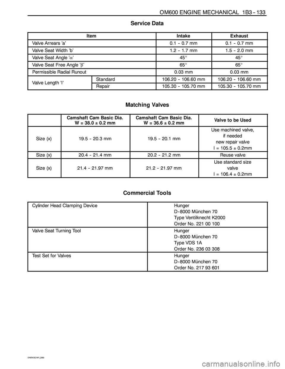
Service Data
ItemIntakeExhaust
Valve Arrears ’a’0.1 -- 0.7 mm0.1 -- 0.7 mm
Valve Seat Width ’b’1.2 -- 1.7 mm1.5 -- 2.0 mm
Valve Seat Angle ’α’45_45_
Valve Seat Free Angle ’β’65_65_
Permissible Radial Runout0.03 mm0.03 mm
ValveLength’I’Standard106.20 -- 106.60 mm106.20 -- 106.60 mmValveLength’I’Repair105.30 -- 105.70 mm105.30 -- 105.70 mm
Matching Valves
Camshaft Cam Basic Dia.
W = 38.0±0.2 mmCamshaft Cam Basic Dia.
W=36.6±0.2 mmValvetobeUsed
Size (x)19.5 -- 20.3 mm19.5 -- 20.1 mm
Use machined valve,
if needed
new repair valve
I = 105.5±0.2mm
Size (x)20.4 -- 21.4 mm20.2 -- 21.2 mmReuse valve
Size (x)21.4 -- 21.97 mm21.2 -- 21.97 mm
Use standard size
valve
I = 106.4±0.2mm
Commercial Tools
Cylinder Head Clamping DeviceHunger
D-- 8000 München 70
Type Ventilknecht K2000
Order No. 221 00 100
Valve Seat Turning ToolHunger
D-- 8000 München 70
Ty p e VDS 1 A
Order No. 236 03 308
Test Set for ValvesHunger
D-- 8000 München 70
Order No. 217 93 601
Page 685 of 2053
1B3 -- 136 OM600 ENGINE MECHANICAL
D AEW OO M Y_2000
I Length of Valve
w Camshaft Cam Basic Circle Diameter
x Distance (Camshaft basic bore -- valve stem)y Half Camshaft Basic Bore Diameter
z Distance (Cylinder head cover parting surface --
valve stem)
8. Measure ’x’ (Camshaft basic bore -- valve stem).
’x’ = ’z’ -- ’y’
9. Determine the valve to be used.
(See ’Matching valves’)
Example) Measured value ’w’ = 38.2 mm
Measured value ’z’ = 36.5 mm
Value ’y’ = 15.5 mm
’x’ = 36.5 -- 15.5 = 21.0 mm
In the case of a camshaft cam basic circle diameter
’w’ = 38.2mm and a distance ’x’ = 21.0mm, the
installed valve may be used.
Page 693 of 2053
1B3 -- 144 OM600 ENGINE MECHANICAL
D AEW OO M Y_2000
Notice
If max. length ’L’ of the 12-- sided bolt exceeds
53.6mm, replace it.
8. Install the chain tensioner.
Tightening Torque80 N∙m (59 lb-ft)
Notice
Replace the seal.
Before installation, by pumping in the oil approx. 10
times, fill the oil.
9. Remove the engine lock.
10. Check the TDC marking of OT on the crankshaft.