1997 SSANGYONG KORANDO length
[x] Cancel search: lengthPage 1151 of 2053
5A-56 AUTOMATIC TRANSMISSION
SSANGYONG MY2002
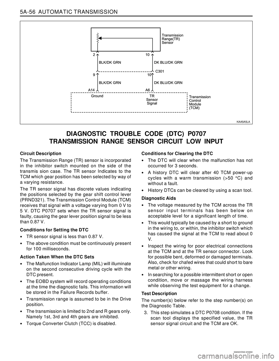
Circuit Description
The Transmission Range (TR) sensor is incorporated
in the inhibitor switch mounted on the side of the
transmis sion case. The TR sensor Indicates to the
TCM which gear position has been selected by way of
a varying resistance.
The TR sensor signal has discrete values indicating
the positions selected by the gear shift control lever
(PRND321). The Transmission Control Module (TCM)
receives that signal with a voltage varying from 0 V to
5 V. DTC P0707 sets when the TR sensor signal is
faulty, causing the gear lever position signal to be less
than 0.87 V.
Conditions for Setting the DTC
TR sensor signal is less than 0.87 V.
The above condition must be continuously present
for 100 milliseconds.
Action Taken When the DTC Sets
The Malfunction Indicator Lamp (MIL) will illuminate
on the second consecutive driving cycle with the
DTC present.
The EOBD system will record operating conditions
at the time the diagnostic fails. This information will
be stored in the Failure Records buffer.
Transmission range is assumed to be in the Drive
position.
The transmission is limited to 2nd and R gears only.
Namely 1st, 3rd and 4th gears are inhibited.
Torque Converter Clutch (TCC) is disabled.
DIAGNOSTIC TROUBLE CODE (DTC) P0707
TRANSMISSION RANGE SENSOR CIRCUIT LOW INPUT
Conditions for Clearing the DTC
The DTC will clear when the malfunction has not
occurred for 3 seconds.
A history DTC will clear after 40 TCM power-up
cycles with a warm transmission (>50 °C) and
without a fault.
History DTCs can be cleared by using a scan tool.
Diagnostic Aids
The voltage measured by the TCM across the TR
sensor input terminals has been below on
acceptable level for a significant length of time.
This would typically be caused by a short to ground
in the wiring to, or within, the inhibitor switch which
has caused the signal at the TCM to read about 0
V.
Inspect the wiring for poor electrical connections
at the TCM and at the TR sensor connector. Look
for possible bent, deformed or damaged terminals.
Also, check for chafed wires that could short to bare
metal or other wiring.
In searching for a possible intermittent short or open
condition, move or massage the wiring harness
while observing the test equipment for a change.
Test Description
The number(s) below refer to the step number(s) on
the Diagnostic Table.
3. This step simulates a DTC P0708 condition. If the
scan tool displays the specified value, the TR
sensor signal circuit and the TCM are OK.
KAA5A5LA
Page 1153 of 2053
5A-58 AUTOMATIC TRANSMISSION
SSANGYONG MY2002
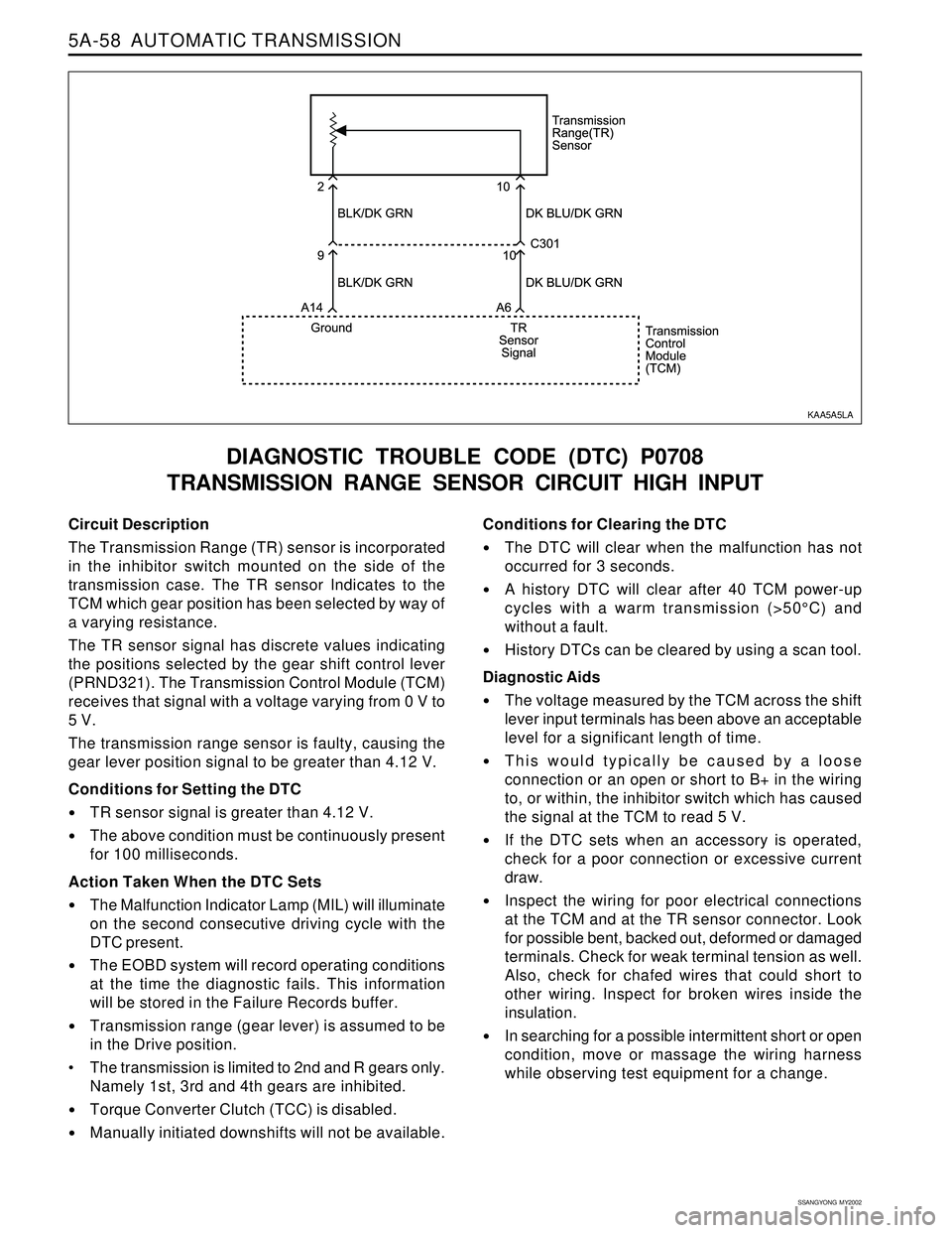
Circuit Description
The Transmission Range (TR) sensor is incorporated
in the inhibitor switch mounted on the side of the
transmission case. The TR sensor Indicates to the
TCM which gear position has been selected by way of
a varying resistance.
The TR sensor signal has discrete values indicating
the positions selected by the gear shift control lever
(PRND321). The Transmission Control Module (TCM)
receives that signal with a voltage varying from 0 V to
5 V.
The transmission range sensor is faulty, causing the
gear lever position signal to be greater than 4.12 V.
Conditions for Setting the DTC
TR sensor signal is greater than 4.12 V.
The above condition must be continuously present
for 100 milliseconds.
Action Taken When the DTC Sets
The Malfunction Indicator Lamp (MIL) will illuminate
on the second consecutive driving cycle with the
DTC present.
The EOBD system will record operating conditions
at the time the diagnostic fails. This information
will be stored in the Failure Records buffer.
Transmission range (gear lever) is assumed to be
in the Drive position.
The transmission is limited to 2nd and R gears only.
Namely 1st, 3rd and 4th gears are inhibited.
Torque Converter Clutch (TCC) is disabled.
Manually initiated downshifts will not be available.
DIAGNOSTIC TROUBLE CODE (DTC) P0708
TRANSMISSION RANGE SENSOR CIRCUIT HIGH INPUT
Conditions for Clearing the DTC
The DTC will clear when the malfunction has not
occurred for 3 seconds.
A history DTC will clear after 40 TCM power-up
cycles with a warm transmission (>50°C) and
without a fault.
History DTCs can be cleared by using a scan tool.
Diagnostic Aids
The voltage measured by the TCM across the shift
lever input terminals has been above an acceptable
level for a significant length of time.
This would typically be caused by a loose
connection or an open or short to B+ in the wiring
to, or within, the inhibitor switch which has caused
the signal at the TCM to read 5 V.
If the DTC sets when an accessory is operated,
check for a poor connection or excessive current
draw.
Inspect the wiring for poor electrical connections
at the TCM and at the TR sensor connector. Look
for possible bent, backed out, deformed or damaged
terminals. Check for weak terminal tension as well.
Also, check for chafed wires that could short to
other wiring. Inspect for broken wires inside the
insulation.
In searching for a possible intermittent short or open
condition, move or massage the wiring harness
while observing test equipment for a change.
KAA5A5LA
Page 1446 of 2053
SSANGYONG MY2002
6A-4 POWER STEERING SYSTEM
KAA6A020
DIAGNOSTIC INFORMATION AND PROCEDURES
POWER STEERING SYSTEM
PRESSURE TEST
Tools Required
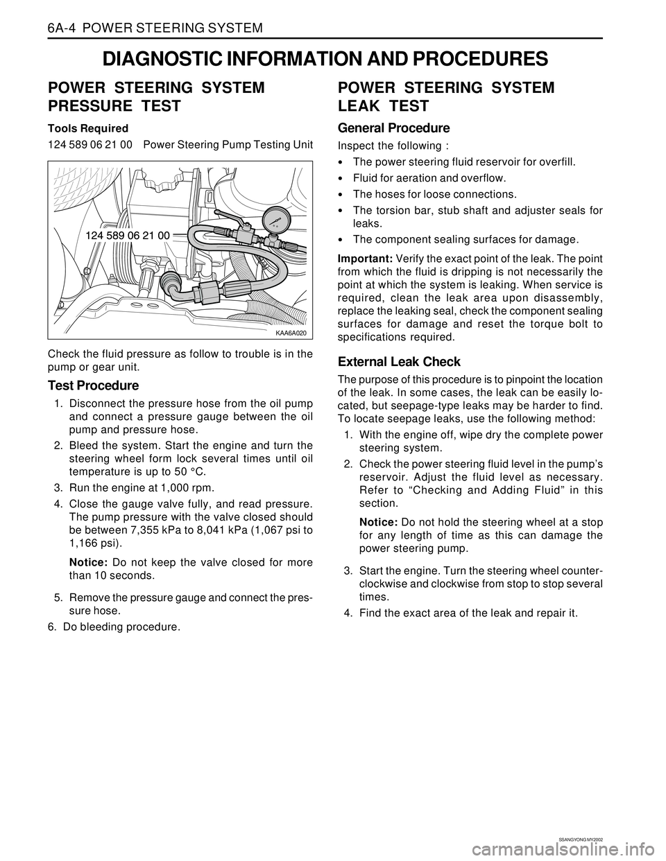
124 589 06 21 00 Power Steering Pump Testing Unit
Check the fluid pressure as follow to trouble is in the
pump or gear unit.
Test Procedure
1. Disconnect the pressure hose from the oil pump
and connect a pressure gauge between the oil
pump and pressure hose.
2. Bleed the system. Start the engine and turn the
steering wheel form lock several times until oil
temperature is up to 50 °C.
3. Run the engine at 1,000 rpm.
4. Close the gauge valve fully, and read pressure.
The pump pressure with the valve closed should
be between 7,355 kPa to 8,041 kPa (1,067 psi to
1,166 psi).
Notice: Do not keep the valve closed for more
than 10 seconds.
5. Remove the pressure gauge and connect the pres-
sure hose.
6. Do bleeding procedure.
POWER STEERING SYSTEM
LEAK TEST
General Procedure
Inspect the following :
The power steering fluid reservoir for overfill.
Fluid for aeration and overflow.
The hoses for loose connections.
The torsion bar, stub shaft and adjuster seals for
leaks.
The component sealing surfaces for damage.
Important: Verify the exact point of the leak. The point
from which the fluid is dripping is not necessarily the
point at which the system is leaking. When service is
required, clean the leak area upon disassembly,
replace the leaking seal, check the component sealing
surfaces for damage and reset the torque bolt to
specifications required.
External Leak Check
The purpose of this procedure is to pinpoint the location
of the leak. In some cases, the leak can be easily lo-
cated, but seepage-type leaks may be harder to find.
To locate seepage leaks, use the following method:
1. With the engine off, wipe dry the complete power
steering system.
2. Check the power steering fluid level in the pump’s
reservoir. Adjust the fluid level as necessary.
Refer to “Checking and Adding Fluid” in this
section.
Notice: Do not hold the steering wheel at a stop
for any length of time as this can damage the
power steering pump.
3. Start the engine. Turn the steering wheel counter-
clockwise and clockwise from stop to stop several
times.
4. Find the exact area of the leak and repair it.
Page 1455 of 2053
SSANGYONG MY2002
6A-4 POWER STEERING SYSTEM
KAA6A020
DIAGNOSTIC INFORMATION AND PROCEDURES
POWER STEERING SYSTEM
PRESSURE TEST
Tools Required
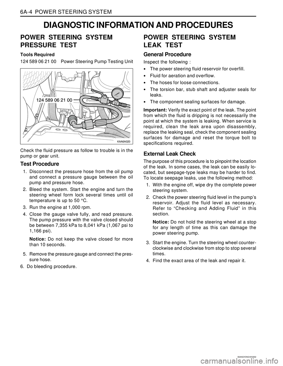
124 589 06 21 00 Power Steering Pump Testing Unit
Check the fluid pressure as follow to trouble is in the
pump or gear unit.
Test Procedure
1. Disconnect the pressure hose from the oil pump
and connect a pressure gauge between the oil
pump and pressure hose.
2. Bleed the system. Start the engine and turn the
steering wheel form lock several times until oil
temperature is up to 50 °C.
3. Run the engine at 1,000 rpm.
4. Close the gauge valve fully, and read pressure.
The pump pressure with the valve closed should
be between 7,355 kPa to 8,041 kPa (1,067 psi to
1,166 psi).
Notice: Do not keep the valve closed for more
than 10 seconds.
5. Remove the pressure gauge and connect the pres-
sure hose.
6. Do bleeding procedure.
POWER STEERING SYSTEM
LEAK TEST
General Procedure
Inspect the following :
The power steering fluid reservoir for overfill.
Fluid for aeration and overflow.
The hoses for loose connections.
The torsion bar, stub shaft and adjuster seals for
leaks.
The component sealing surfaces for damage.
Important: Verify the exact point of the leak. The point
from which the fluid is dripping is not necessarily the
point at which the system is leaking. When service is
required, clean the leak area upon disassembly,
replace the leaking seal, check the component sealing
surfaces for damage and reset the torque bolt to
specifications required.
External Leak Check
The purpose of this procedure is to pinpoint the location
of the leak. In some cases, the leak can be easily lo-
cated, but seepage-type leaks may be harder to find.
To locate seepage leaks, use the following method:
1. With the engine off, wipe dry the complete power
steering system.
2. Check the power steering fluid level in the pump’s
reservoir. Adjust the fluid level as necessary.
Refer to “Checking and Adding Fluid” in this
section.
Notice: Do not hold the steering wheel at a stop
for any length of time as this can damage the
power steering pump.
3. Start the engine. Turn the steering wheel counter-
clockwise and clockwise from stop to stop several
times.
4. Find the exact area of the leak and repair it.
Page 1482 of 2053
SSANGYONG MY2002
6C-14 POWER STEERING GEAR
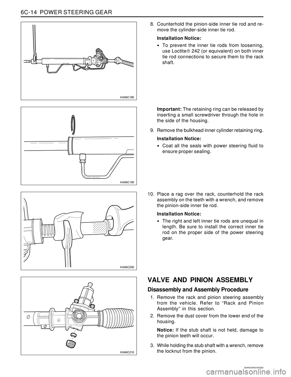
8. Counterhold the pinion-side inner tie rod and re-
move the cylinder-side inner tie rod.
Installation Notice:
To prevent the inner tie rods from loosening,
use Loctite 242 (or equivalent) on both inner
tie rod connections to secure them to the rack
shaft.
KAA6C180
KAA6C190
KAA6C210
KAA6C200
Important: The retaining ring can be released by
inserting a small screwdriver through the hole in
the side of the housing.
9. Remove the bulkhead inner cylinder retaining ring.
Installation Notice:
Coat all the seals with power steering fluid to
ensure proper sealing.
10. Place a rag over the rack, counterhold the rack
assembly on the teeth with a wrench, and remove
the pinion-side inner tie rod.
Installation Notice:
The right and left inner tie rods are unequal in
length. Be sure to install the correct inner tie
rod on the proper side of the power steering
gear.
VALVE AND PINION ASSEMBLY
Disassembly and Assembly Procedure
1. Remove the rack and pinion steering assembly
from the vehicle. Refer to “Rack and Pinion
Assembly” in this section.
2. Remove the dust cover from the lower end of the
housing.
Notice: If the stub shaft is not held, damage to
the pinion teeth will occur.
3. While holding the stub shaft with a wrench, remove
the locknut from the pinion.
Page 1519 of 2053
SSANGYONG MY2002
7A-18 HEATING AND VENTILATION SYSTEM
ON-VEHICLE SERVICE
TEMPREATURE CONTROL CABLE
ADJUSTMENT
Because the cable and the cable housing have fixed
lengths, it is impossible to make a temperature cable
adjustment.
The heater/air distributor case linkage also cannot be
adjusted.
If a malfunction is suspected, verify the proper
operation of the controller and the mechanical doors
for heater/air distributor case assembly.
MAINTENANCE AND REPAIR
KAA7A020
KAA7A030
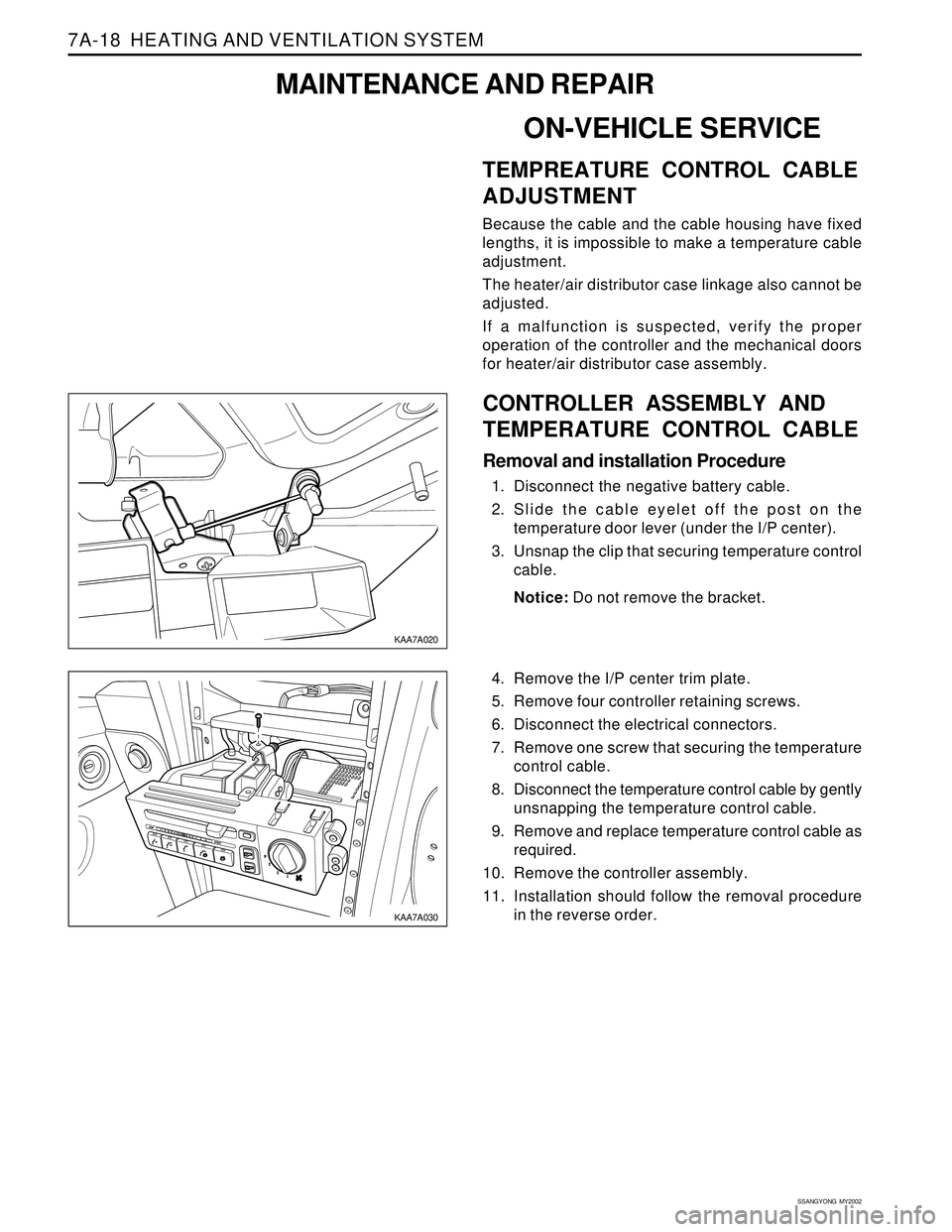
CONTROLLER ASSEMBLY AND
TEMPERATURE CONTROL CABLE
Removal and installation Procedure
1. Disconnect the negative battery cable.
2. Slide the cable eyelet off the post on the
temperature door lever (under the I/P center).
3. Unsnap the clip that securing temperature control
cable.
Notice: Do not remove the bracket.
4. Remove the I/P center trim plate.
5. Remove four controller retaining screws.
6. Disconnect the electrical connectors.
7. Remove one screw that securing the temperature
control cable.
8. Disconnect the temperature control cable by gently
unsnapping the temperature control cable.
9. Remove and replace temperature control cable as
required.
10. Remove the controller assembly.
11. Installation should follow the removal procedure
in the reverse order.
Page 1578 of 2053
SSANGYONG MY2002
8A-2 SEAT BELTS
DESCRIPTION AND OPERATION
DRIVER SEAT BELT WARNING
The driver’s seat belt incorporates a seat belt warning
lamp in the instrument cluster to remind the driver if
the seat belt is not fastened when the ignition is turned
ON. The warning lamp blinks for eight seconds with
chime and goes out.
THREE-POINT FRONT SEAT BELT
WITH PRETENSIONER
The front seat belt contains an electronically controlled
pyrotechnic retractor, pretensioner, which reduces seat
belt slack when it activated in a head-on or angled
front collision. The front seat belt must be replaced
after an accident that causes its activation. At normal
condition the driver’s seat belt operates as emergency
locking retractor (ELR).
Emergency Locking Retractor (ELR)
The ELR seat belt is always unlocked, allowing the
passenger freedom of movement, except in
emergencies such as rapid deceleration, rapid
acceleration, or hard cornering maneuvers.
THREE-POINT REAR OUTBOARD
SEAT BELT
The rear outboard seating position uses the emergency
locking retractor (ELR). Refer to Three-point front seat
belt with pretensioner in this section for details.
TWO-POINT LAP REAR CENTER
SEAT BELT
The two-point lap rear center seat belt is a single contin-
uous length of webbing. The webbing is routed from
the anchor through plate and into a single retractor.
OPERATIONAL AND FUNCTIONAL
CHECKS
Caution:
Keep sharp objects and potentially damaged ob
jects away from seat belts.
Avoid bending or damaging any portion of
buckle or the latch plate
Do not breach or dye the belt webbing. Use only
mild soap and water in order to clean the belts.
When installing the seat belt anchor bolts and
screws, start the bolts and screws by hand in or-
der to prevent cross-threading.
Do not attempt any repairs on the retractor mech-
anisms or covers. Replace any defective assem-
blies with new assemblies.
Replace any belts that are cut or damaged in any
way.
1. Inspect all seat anchor bolts and screws in order to
verify that they are secure.
2. Inspect the seat belt buckle. The buckle must lock
and unlock easily.
3. After inserting the latch into the buckle, tug sharply
on the belt. The buckle must remain locked.
4. Fully extend the shoulder belt portion to make sure
that there is no twisting or tears in the belt.
5. Let the shoulder belt retract fully. The belt should
retract easily.
CHILD SEAT TETHER ANCHOR
There are three child seat tether anchors to hold the
child seat firmly. One is located rear center of ceiling
and two are located on the rear corner of floor.
Page 1807 of 2053
FRAME AND UNDERBODY 9N-5
SSANGYONG MY2002
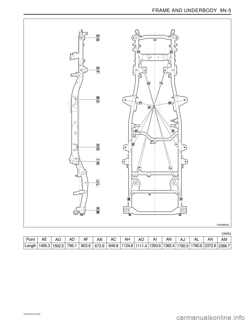
KAA9N020
Point
LengthAE
1495.3AG
1502.5AD
796.1AF
803.6AB
672.6AC
648.8AH
1124.8AO
1111.4AI
1393.6AN
1382.4AJ
1785.9AL
1780.6AK
2372.8AM
2366.7
(mm)