1997 SSANGYONG KORANDO display
[x] Cancel search: displayPage 1043 of 2053
SSANGYONG MY2002
4F-60 ABS AND TCS
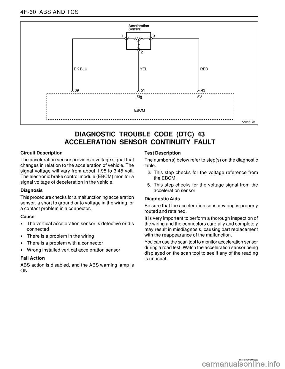
DIAGNOSTIC TROUBLE CODE (DTC) 43
ACCELERATION SENSOR CONTINUITY FAULT
KAA4F190
Circuit Description
The acceleration sensor provides a voltage signal that
changes in relation to the acceleration of vehicle. The
signal voltage will vary from about 1.95 to 3.45 volt.
The electronic brake control module (EBCM) monitor a
signal voltage of deceleration in the vehicle.
Diagnosis
This procedure checks for a malfunctioning acceleration
sensor, a short to ground or to voltage in the wiring, or
a contact problem in a connector.
Cause
The vertical acceleration sensor is defective or dis
connected
There is a problem in the wiring
There is a problem with a connector
Wrong installed vertical acceleration sensor
Fail Action
ABS action is disabled, and the ABS warning lamp is
ON.Test Description
The number(s) below refer to step(s) on the diagnostic
table.
2. This step checks for the voltage reference from
the EBCM.
5. This step checks for the voltage signal from the
acceleration sensor.
Diagnostic Aids
Be sure that the acceleration sensor wiring is properly
routed and retained.
It is very important to perform a thorough inspection of
the wiring and the connectors carefully and completely
may result in misdiagnosis, causing part replacement
with the reappearance of the malfunction.
You can use the scan tool to monitor acceleration sensor
during a road test. Watch the acceleration sensor being
displayed on the scan tool to see if any of the reading
is unusual.
Page 1102 of 2053
5A-8 AUTOMATIC TRANSMISSION
SSANGYONG MY2002
Solenoid Valve Symbols
(ON/OFF Solenoids)
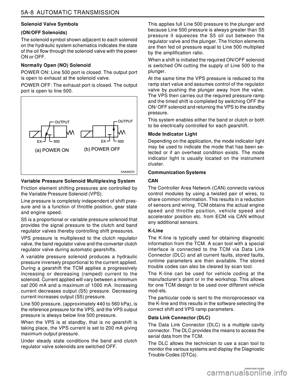
The solenoid symbol shown adjacent to each solenoid
on the hydraulic system schematics indicates the state
of the oil flow through the solenoid valve with the power
ON or OFF.
Normally Open (NO) Solenoid
POWER ON: Line 500 port is closed. The output port
is open to exhaust at the solenoid valve.
POWER OFF: The exhaust port is closed. The output
port is open to line 500.
Variable Pressure Solenoid Multiplexing System
Friction element shifting pressures are controlled by
the Variable Pressure Solenoid (VPS).
Line pressure is completely independent of shift pres-
sure and is a function of throttle position, gear state
and engine speed.
S5 is a proportional or variable pressure solenoid that
provides the signal pressure to the clutch and band
regulator valves thereby controlling shift pressures.
VPS pressure is multiplexed to the clutch regulator
valve, the band regulator valve and the converter clutch
regulator valve during automatic gearshifts.
A variable pressure solenoid produces a hydraulic
pressure inversely proportional to the current applied.
During a gearshift the TCM applies a progressively
increasing or decreasing (ramped) current to the
solenoid. Current applied will vary between a minimum
oaf 200 mA and a maximum of 1000 mA. Increasing
current decreases output (S5) pressure. Decreasing
current increases output (S5) pressure.
Line 500 pressure, (approximately 440 to 560 kPa), is
the reference pressure for the VPS, and the VPS output
pressure is always below line 500 pressure.
When the VPS is at standby, that is no gearshift is
taking place, the VPS current is set to 200 mA giving
maximum output pressure.
Under steady state conditions the band and clutch
regulator valve solenoids are switched OFF.This applies full Line 500 pressure to the plunger and
because Line 500 pressure is always greater than S5
pressure it squeezes the S5 oil out between the
regulator valve and the plunger. The friction elements
are then fed oil pressure equal to Line 500 multiplied
by the amplification ratio.
When a shift is initiated the required ON/OFF solenoid
is switched ON cutting the supply of Line 500 to the
plunger.
At the same time the VPS pressure is reduced to the
ramp start value and assumes control of the regulator
valve by pushing the plunger away from the valve.
The VPS then carries out the required pressure ramp
and the timed shift is completed by switching OFF the
ON/ OFF solenoid and returning the VPS to the standby
pressure.
This system enables either the band or clutch or both
to be electrically controlled for each gearshift.
Mode Indicator Light
Depending on the application, the mode indicator light
may be used to indicate the mode that has been se-
lected or if an overheat condition exists. The mode
indicator light is usually located on the instrument
cluster.
Communication Systems
CAN
The Controller Area Network (CAN) connects various
control modules by using a twisted pair of wires, to
share common information. This results in a reduction
of sensors and wiring. TCM obtains the actual engine
speed and throttle position, vehicle speed and
accelerator position etc. from ECM via CAN without
any additional sensors.
K-Line
The K-line is typically used for obtaining diagnostic
information from the TCM. A scan tool with a special
interface is connected to the TCM via Data Link
Connector (DLC) and all current faults, stored faults,
runtime parameters are then available. The stored
trouble codes can also be cleared by scan tool.
The K-line can be used for vehicle coding at the
manufacturer’s plant or in the workshop. This allows
for one TCM design to be used over different vehicle
mod-els.
The particular code is sent to the microprocessor via
the K-line and this results in the software selecting the
correct shift and VPS ramp parameters.
Data Link Connector (DLC)
The Data Link Connector (DLC) is a multiple cavity
connector. The DLC provides the means to access the
serial data from the TCM.
The DLC allows the technician to use a scan tool to
monitor the various systems and display the Diagnostic
Trouble Codes (DTCs).
KAA5A070
Page 1147 of 2053
5A-52 AUTOMATIC TRANSMISSION
SSANGYONG MY2002
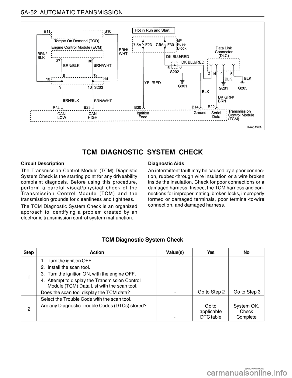
Circuit Description
The Transmission Control Module (TCM) Diagnistic
System Check is the starting point for any driveability
complaint diagnosis. Before using this procedure,
perform a careful visual/physical check of the
Transmission Control Module (TCM) and the
transmission grounds for cleanliness and tightness.
The TCM Diagnostic System Check is an organized
approach to identifying a problem created by an
electronic transmission control system malfunction.
TCM DIAGNOSTIC SYSTEM CHECK
Diagnostic Aids
An intermittent fault may be caused by a poor connec-
tion, rubbed-through wire insulation or a wire broken
inside the insulation. Check for poor connections or a
damaged harness. Inspect the TCM harness and con-
nections for improper mating, broken locks, improperly
formed or damaged terminals, poor terminal-to-wire
connection, and damaged harness.
TCM Diagnostic System Check
1
StepAction Value(s) Yes No
21 Turn the ignition OFF.
2. Install the scan tool.
3. Turn the ignition ON, with the engine OFF.
4. Attempt to display the Transmission Control
Module (TCM) Data List with the scan tool.
Does the scan tool display the TCM data?
Select the Trouble Code with the scan tool.
Are any Diagnostic Trouble Codes (DTCs) stored?
- Go to Step 2 Go to Step 3
Go to
applicable
DTC table -System OK,
Check
Complete
KAA5A5KA
Page 1150 of 2053
AUTOMATIC TRANSMISSION 5A-55
SSANGYONG MY2002
Perform a Transmission Control Module (TCM)
Diagnostic System Check.
Is the check performed?
1. Install the scan tool.
2. Turn the ignition ON, with the engine OFF.
3. Record and then clear DTCs.
4. Operate the vehicle within the conditions for
setting this DTC as specified in the text.
Does the scan tool display P0706?
1. Select Gear Lever Position on scan tool Data List.
2. Move the gear shift control lever through all of the
gear ranges (P, R, N, D, 3, 2, 1).
Does the scan tool display the correct gear lever
positions?
1. Inspect the TR sensor for damage to its rotating
part or its mountings.
2. Inspect the shaft driving the TR sensor for damage.
Is a repair necessary?
Replace the TR sensor or driving shaft as appropriate.
Is the acting complete?
Check for damage to the z-link within the transmission
and repair as necessary.
Is a repair necessary?
1. Using the scan tool, clear the DTCs.
2. Road test the vehicle within the conditions for
setting this DTC as specified in the text.
Does the scan tool indicate that this diagnostic has
run and passed?
Check if any DTCs are set.
Are there any DTCs displayed or previously recorded
at Step 2 that have not been diagnosed?
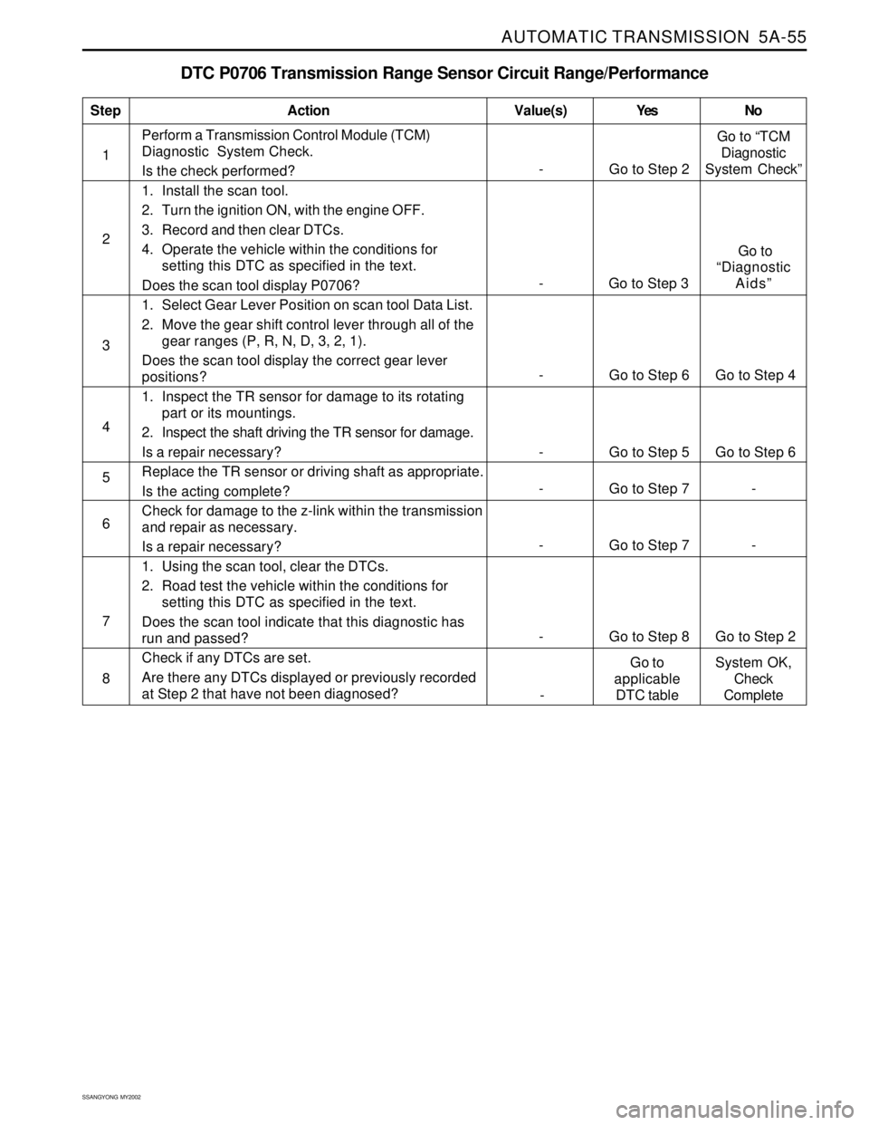
DTC P0706 Transmission Range Sensor Circuit Range/Performance
1
StepAction Value(s) Yes No
2
3
4
5
6
- Go to Step 2Go to “TCM
Diagnostic
System Check”
- Go to Step 6 Go to Step 4
- Go to Step 5 Go to Step 6
- Go to Step 7 -
8 7
- Go to Step 8 Go to Step 2
- Go to Step 7 -
- Go to Step 3 Go to
“Diagnostic
Aids”
-Go to
applicable
DTC tableSystem OK,
Check
Complete
Page 1151 of 2053
5A-56 AUTOMATIC TRANSMISSION
SSANGYONG MY2002
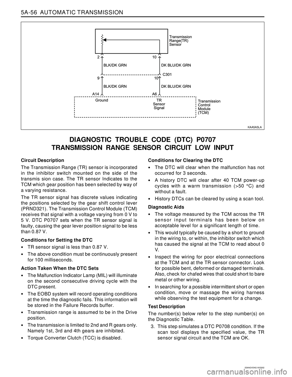
Circuit Description
The Transmission Range (TR) sensor is incorporated
in the inhibitor switch mounted on the side of the
transmis sion case. The TR sensor Indicates to the
TCM which gear position has been selected by way of
a varying resistance.
The TR sensor signal has discrete values indicating
the positions selected by the gear shift control lever
(PRND321). The Transmission Control Module (TCM)
receives that signal with a voltage varying from 0 V to
5 V. DTC P0707 sets when the TR sensor signal is
faulty, causing the gear lever position signal to be less
than 0.87 V.
Conditions for Setting the DTC
TR sensor signal is less than 0.87 V.
The above condition must be continuously present
for 100 milliseconds.
Action Taken When the DTC Sets
The Malfunction Indicator Lamp (MIL) will illuminate
on the second consecutive driving cycle with the
DTC present.
The EOBD system will record operating conditions
at the time the diagnostic fails. This information will
be stored in the Failure Records buffer.
Transmission range is assumed to be in the Drive
position.
The transmission is limited to 2nd and R gears only.
Namely 1st, 3rd and 4th gears are inhibited.
Torque Converter Clutch (TCC) is disabled.
DIAGNOSTIC TROUBLE CODE (DTC) P0707
TRANSMISSION RANGE SENSOR CIRCUIT LOW INPUT
Conditions for Clearing the DTC
The DTC will clear when the malfunction has not
occurred for 3 seconds.
A history DTC will clear after 40 TCM power-up
cycles with a warm transmission (>50 °C) and
without a fault.
History DTCs can be cleared by using a scan tool.
Diagnostic Aids
The voltage measured by the TCM across the TR
sensor input terminals has been below on
acceptable level for a significant length of time.
This would typically be caused by a short to ground
in the wiring to, or within, the inhibitor switch which
has caused the signal at the TCM to read about 0
V.
Inspect the wiring for poor electrical connections
at the TCM and at the TR sensor connector. Look
for possible bent, deformed or damaged terminals.
Also, check for chafed wires that could short to bare
metal or other wiring.
In searching for a possible intermittent short or open
condition, move or massage the wiring harness
while observing the test equipment for a change.
Test Description
The number(s) below refer to the step number(s) on
the Diagnostic Table.
3. This step simulates a DTC P0708 condition. If the
scan tool displays the specified value, the TR
sensor signal circuit and the TCM are OK.
KAA5A5LA
Page 1152 of 2053
AUTOMATIC TRANSMISSION 5A-57
SSANGYONG MY2002
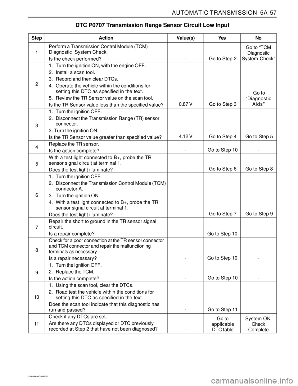
DTC P0707 Transmission Range Sensor Circuit Low Input
1Perform a Transmission Control Module (TCM)
Diagnostic System Check.
Is the check performed?
1. Turn the ignition ON, with the engine OFF.
2. Install a scan tool.
3. Record and then clear DTCs.
4. Operate the vehicle within the conditions for
setting this DTC as specified in the text.
5. Review the TR Sensor value on the scan tool.
Is the TR Sensor value less than the specified value?
1. Turn the ignition OFF.
2. Disconnect the Transmission Range (TR) sensor
connector.
3. Turn the ignition ON.
Is the TR Sensor value greater than specified value?
Replace the TR sensor.
Is the action complete?
With a test light connected to B+, probe the TR
sensor signal circuit at terminal 1.
Does the test light illuminate?
1. Turn the ignition OFF.
2. Disconnect the Transmission Control Module (TCM)
connector A.
3. Turn the ignition ON.
4. With a test light connected to B+, probe the TR
sensor signal circuit at terminal 1.
Does the test light illuminate?
Repair the short to ground in the TR sensor signal
circuit.
Is a repair complete?
Check for a poor connection at the TR sensor connector
and TCM connector and repair the malfunctioning
terminals as necessary.
Is a repair necessary?
1. Turn the ignition OFF.
2. Replace the TCM.
Is the action complete?
1. Using the scan tool, clear the DTCs.
2. Road test the vehicle within the conditions for
setting this DTC as specified in the text.
Does the scan tool indicate that this diagnostic has
run and passed?
Check if any DTCs are set.
Are there any DTCs displayed or DTC previously
recorded at Step 2 that have not been diagnosed?
StepAction Value(s) Yes No
2
3
- Go to Step 6 Go to Step 8 5
- Go to Step 7 Go to Step 9 6
- Go to Step 10 - 4
7
- Go to Step 10 - 8
- Go to Step 10 - 9
- Go to Step 11 10
11
- Go to Step 2Go to “TCM
Diagnostic
System Check”
4.12 V
Go to Step 4 Go to Step 5
0.87 V Go to Step 3 Go to
“Diagnostic
Aids”
-Go to
applicable
DTC tableSystem OK,
Check
Complete
- Go to Step 10 -
Page 1154 of 2053
AUTOMATIC TRANSMISSION 5A-59
SSANGYONG MY2002
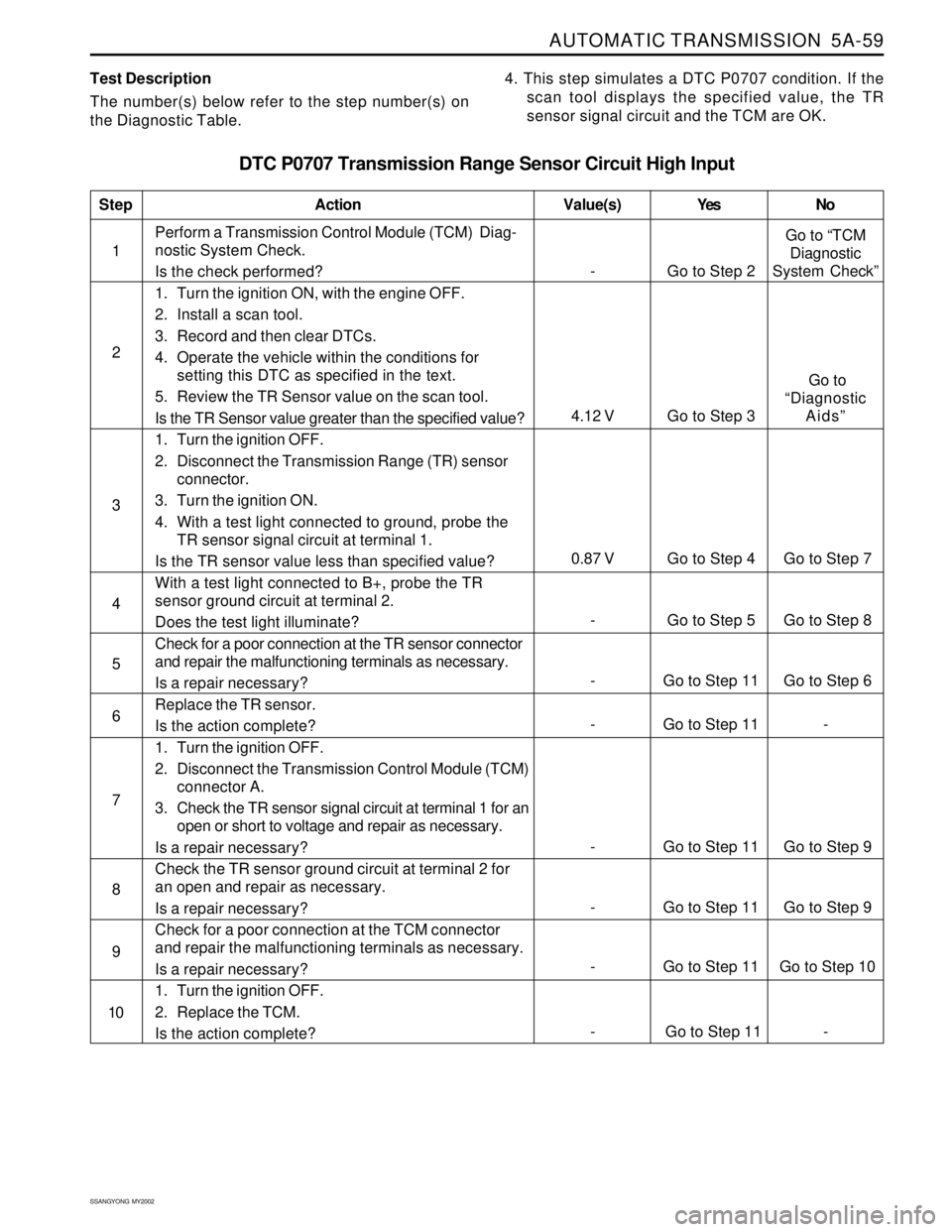
Test Description
The number(s) below refer to the step number(s) on
the Diagnostic Table.4. This step simulates a DTC P0707 condition. If the
scan tool displays the specified value, the TR
sensor signal circuit and the TCM are OK.
DTC P0707 Transmission Range Sensor Circuit High Input
1Perform a Transmission Control Module (TCM) Diag-
nostic System Check.
Is the check performed?
1. Turn the ignition ON, with the engine OFF.
2. Install a scan tool.
3. Record and then clear DTCs.
4. Operate the vehicle within the conditions for
setting this DTC as specified in the text.
5. Review the TR Sensor value on the scan tool.
Is the TR Sensor value greater than the specified value?
1. Turn the ignition OFF.
2. Disconnect the Transmission Range (TR) sensor
connector.
3. Turn the ignition ON.
4. With a test light connected to ground, probe the
TR sensor signal circuit at terminal 1.
Is the TR sensor value less than specified value?
With a test light connected to B+, probe the TR
sensor ground circuit at terminal 2.
Does the test light illuminate?
Check for a poor connection at the TR sensor connector
and repair the malfunctioning terminals as necessary.
Is a repair necessary?
Replace the TR sensor.
Is the action complete?
1. Turn the ignition OFF.
2. Disconnect the Transmission Control Module (TCM)
connector A.
3. Check the TR sensor signal circuit at terminal 1 for an
open or short to voltage and repair as necessary.
Is a repair necessary?
Check the TR sensor ground circuit at terminal 2 for
an open and repair as necessary.
Is a repair necessary?
Check for a poor connection at the TCM connector
and repair the malfunctioning terminals as necessary.
Is a repair necessary?
1. Turn the ignition OFF.
2. Replace the TCM.
Is the action complete?
StepAction Value(s) Yes No
2
3
- Go to Step 11 Go to Step 6 5
- Go to Step 11 - 6
- Go to Step 5 Go to Step 8 4
- Go to Step 11 Go to Step 9 7
- Go to Step 11 Go to Step 9 8
- Go to Step 11 Go to Step 10 9
10
- Go to Step 2Go to “TCM
Diagnostic
System Check”
0.87 V Go to Step 4 Go to Step 7
4.12 V Go to Step 3 Go to
“Diagnostic
Aids”
- Go to Step 11 -
Page 1155 of 2053
5A-60 AUTOMATIC TRANSMISSION
SSANGYONG MY2002
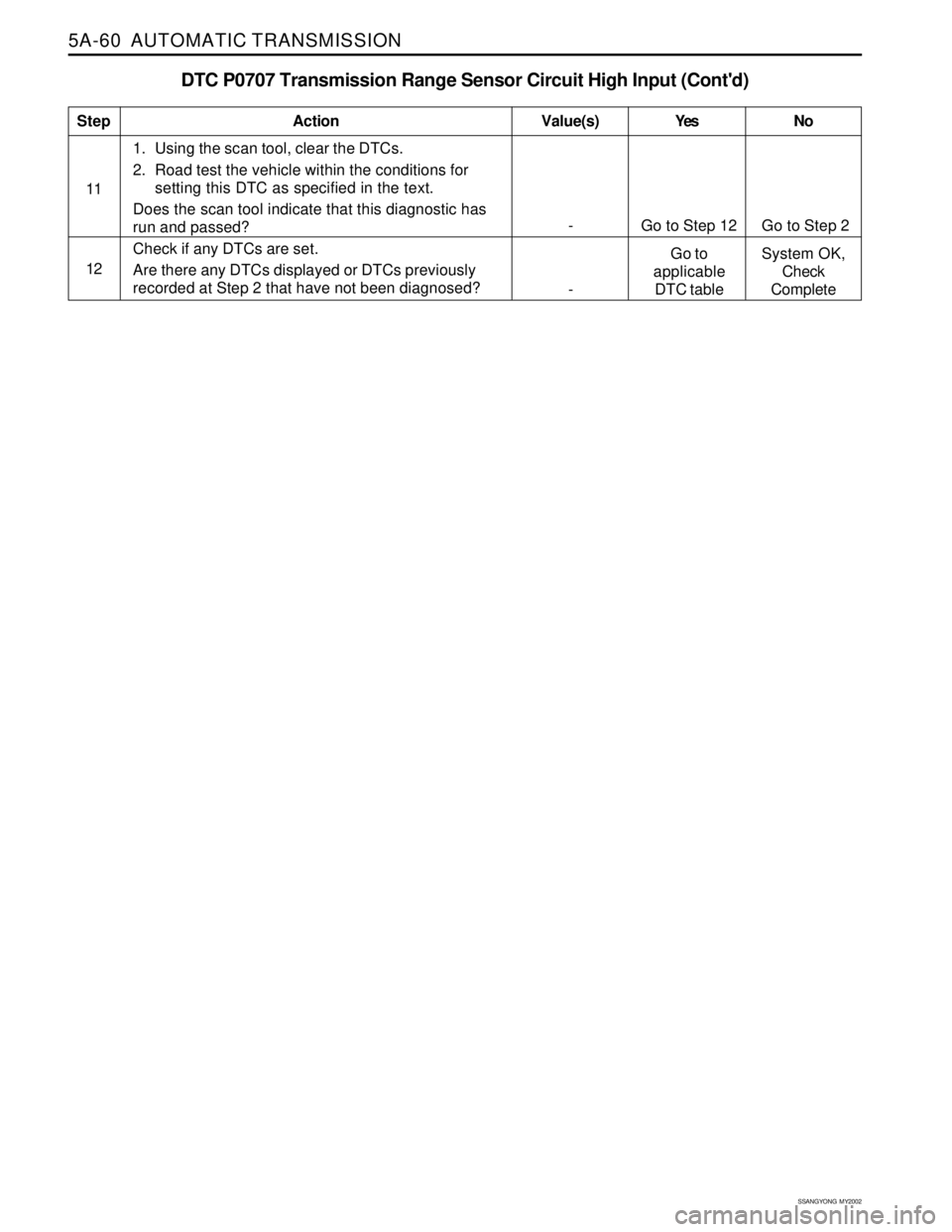
DTC P0707 Transmission Range Sensor Circuit High Input (Cont'd)
111. Using the scan tool, clear the DTCs.
2. Road test the vehicle within the conditions for
setting this DTC as specified in the text.
Does the scan tool indicate that this diagnostic has
run and passed?
Check if any DTCs are set.
Are there any DTCs displayed or DTCs previously
recorded at Step 2 that have not been diagnosed?
StepAction Value(s) Yes No
12
- Go to Step 12 Go to Step 2
-Go to
applicable
DTC tableSystem OK,
Check
Complete