1997 SSANGYONG KORANDO display
[x] Cancel search: displayPage 1157 of 2053
5A-62 AUTOMATIC TRANSMISSION
SSANGYONG MY2002
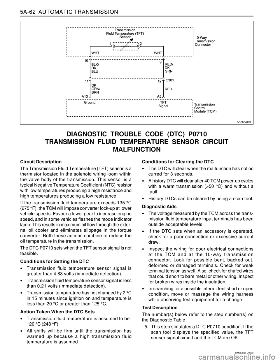
Circuit Description
The Transmission Fluid Temperature (TFT) sensor is a
thermistor located in the solenoid wiring loom within
the valve body of the transmission. This sensor is a
typical Negative Temperature Coefficient (NTC) resistor
with low temperatures producing a high resistance and
high temperatures producing a low resistance.
If the transmission fluid temperature exceeds 135 °C
(275 °F), the TCM will impose converter lock-up at lower
vehicle speeds. Favour a lower gear to increase engine
speed, and in some vehicles flashes the mode indicator
lamp. This results in maximum oil flow through the exter-
nal oil cooler and eliminates slippage in the torque
converter. Both these actions combine to reduce the
oil temperature in the transmission.
The DTC P0710 sets when the TFT sensor signal is not
feasible.
Conditions for Setting the DTC
Transmission fluid temperature sensor signal is
greater than 4.88 volts (immediate detection).
Transmission fluid temperature sensor signal is less
than 0.21 volts (immediate detection).
Transmission temperature has not changed by 2 °C
in 15 minutes since ignition on and temperature is
less than 20 °C or greater than 125 °C.
Action Taken When the DTC Sets
Transmission fluid temperature is assumed to be
120 °C (248 °F).
All shifts will be firm until the transmission has
warmed up because a high transmission fluid
temperature is assumed.
DIAGNOSTIC TROUBLE CODE (DTC) P0710
TRANSMISSION FLUID TEMPERATURE SENSOR CIRCUIT
MALFUNCTION
Conditions for Clearing the DTC
The DTC will clear when the malfunction has not oc
curred for 3 seconds.
A history DTC will clear after 40 TCM power-up cycles
with a warm transmission (>50 °C) and without a
fault.
History DTCs can be cleared by using a scan tool.
Diagnostic Aids
The voltage measured by the TCM across the trans-
mission fluid temperature input terminals has been
outside acceptable levels.
If the DTC sets when an accessory is operated,
check for a poor connection or excessive current
draw.
Inspect the wiring for poor electrical connections
at the TCM and at the 10-way transmission
connector. Look for possible bent, backed out,
deformed or damaged terminals. Check for weak
terminal tension as well. Also, check for chafed wires
that could short to bare metal or other wiring. Inspect
for broken wires inside the insulation.
In searching for a possible intermittent short or open
condition, move or massage the wiring harness
while observing test equipment for a change.
Test Description
The number(s) below refer to the step number(s) on
the Diagnostic Table.
5. This step simulates a DTC P0710 condition. If the
scan tool displays the specified value, the TFT
sensor signal circuit and the TCM are OK.
KAA5A5M0
Page 1159 of 2053
5A-64 AUTOMATIC TRANSMISSION
SSANGYONG MY2002
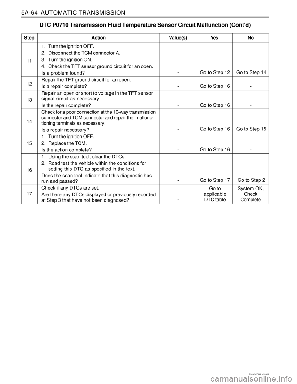
DTC P0710 Transmission Fluid Temperature Sensor Circuit Malfunction (Cont'd)
1. Turn the ignition OFF.
2. Disconnect the TCM connector A.
3. Turn the ignition ON.
4. Check the TFT sensor ground circuit for an open.
Is a problem found?
Repair the TFT ground circuit for an open.
Is a repair complete?
Repair an open or short to voltage in the TFT sensor
signal circuit as necessary.
Is the repair complete?
Check for a poor connection at the 10-way transmission
connector and TCM connector and repair the malfunc-
tioning terminals as necessary.
Is a repair necessary?
1. Turn the ignition OFF.
2. Replace the TCM.
Is the action complete?
1. Using the scan tool, clear the DTCs.
2. Road test the vehicle within the conditions for
setting this DTC as specified in the text.
Does the scan tool indicate that this diagnostic has
run and passed?
Check if any DTCs are set.
Are there any DTCs displayed or previously recorded
at Step 3 that have not been diagnosed?
StepAction Value(s) Yes No
11
12
- Go to Step 12 Go to Step 14
14
- Go to Step 16 -
15 13
- Go to Step 16 -
16
- Go to Step 16 Go to Step 15
17
- Go to Step 16 -
- Go to Step 17 Go to Step 2
-Go to
applicable
DTC tableSystem OK,
Check
Complete
Page 1162 of 2053
AUTOMATIC TRANSMISSION 5A-67
SSANGYONG MY2002
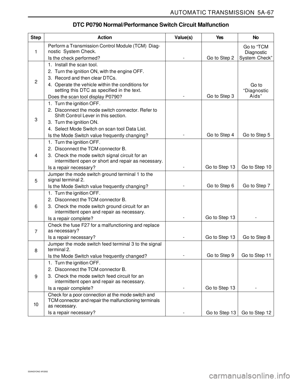
DTC P0790 Normal/Performance Switch Circuit Malfunction
1Perform a Transmission Control Module (TCM) Diag-
nostic System Check.
Is the check performed?
1. Install the scan tool.
2. Turn the ignition ON, with the engine OFF.
3. Record and then clear DTCs.
4. Operate the vehicle within the conditions for
setting this DTC as specified in the text.
Does the scan tool display P0790?
1. Turn the ignition OFF.
2. Disconnect the mode switch connector. Refer to
Shift Control Lever in this section.
3. Turn the ignition ON.
4. Select Mode Switch on scan tool Data List.
Is the Mode Switch value frequently changing?
1. Turn the ignition OFF.
2. Disconnect the TCM connector B.
3. Check the mode switch signal circuit for an
intermittent open or short and repair as necessary.
Is a repair necessary?
Jumper the mode switch ground terminal 1 to the
signal terminal 2.
Is the Mode Switch value frequently changing?
1. Turn the ignition OFF.
2. Disconnect the TCM connector B.
3. Check the mode switch ground circuit for an
intermittent open and repair as necessary.
Is a repair complete?
Check the fuse F27 for a malfunctioning and replace
as necessary?
Is a repair necessary?
Jumper the mode switch feed terminal 3 to the signal
terminal 2.
Is the Mode Switch value frequently changed?
1. Turn the ignition OFF.
2. Disconnect the TCM connector B.
3. Check the mode switch feed circuit for an
intermittent open and repair as necessary.
Is a repair complete?
Check for a poor connection at the mode switch and
TCM connector and repair the malfunctioning terminals
as necessary.
Is a repair necessary?
StepAction Value(s) Yes No
2
3
- Go to Step 6 Go to Step 7 5
- Go to Step 13 - 6
- Go to Step 13 Go to Step 10 4
- Go to Step 13 Go to Step 8 7
- Go to Step 9 Go to Step 11 8
- Go to Step 13 - 9
10
- Go to Step 2Go to “TCM
Diagnostic
System Check”
-
Go to Step 4 Go to Step 5
- Go to Step 3 Go to
“Diagnostic
Aids”
- Go to Step 13 Go to Step 12
Page 1163 of 2053
5A-68 AUTOMATIC TRANSMISSION
SSANGYONG MY2002
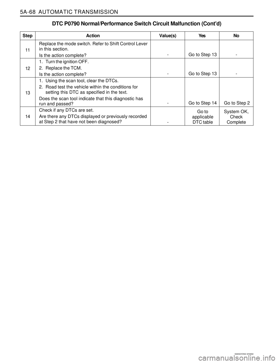
DTC P0790 Normal/Performance Switch Circuit Malfunction (Cont'd)
Replace the mode switch. Refer to Shift Control Lever
in this section.
Is the action complete?
1. Turn the ignition OFF.
2. Replace the TCM.
Is the action complete?
1. Using the scan tool, clear the DTCs.
2. Road test the vehicle within the conditions for
setting this DTC as specified in the text.
Does the scan tool indicate that this diagnostic has
run and passed?
Check if any DTCs are set.
Are there any DTCs displayed or previously recorded
at Step 2 that have not been diagnosed?
StepAction Value(s) Yes No
11
12
- Go to Step 14 Go to Step 2
14
- Go to Step 13 -
13
- Go to Step 13 -
-Go to
applicable
DTC tableSystem OK,
Check
Complete
Page 1166 of 2053
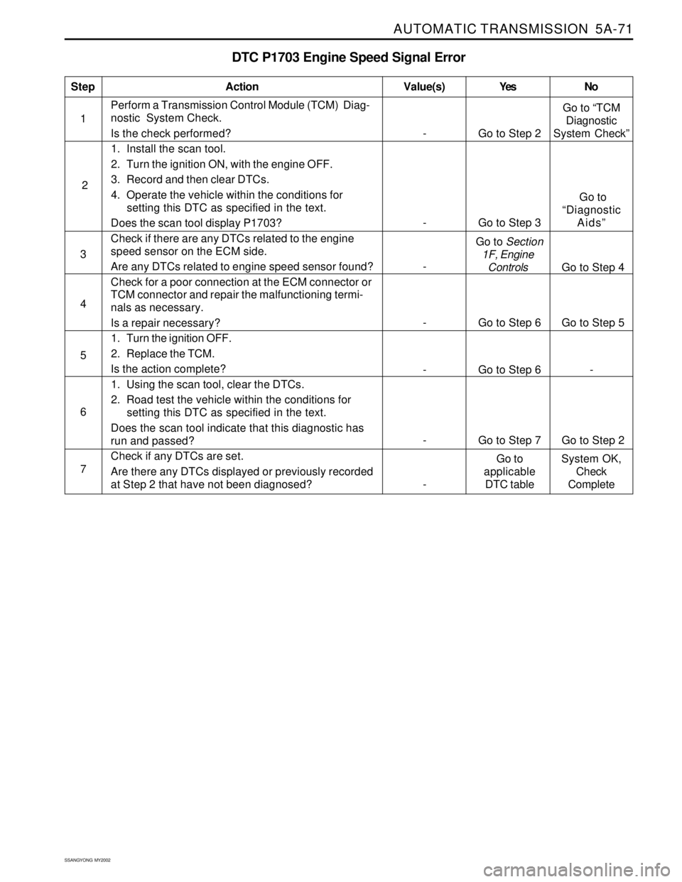
AUTOMATIC TRANSMISSION 5A-71
SSANGYONG MY2002
DTC P1703 Engine Speed Signal Error
1Perform a Transmission Control Module (TCM) Diag-
nostic System Check.
Is the check performed?
1. Install the scan tool.
2. Turn the ignition ON, with the engine OFF.
3. Record and then clear DTCs.
4. Operate the vehicle within the conditions for
setting this DTC as specified in the text.
Does the scan tool display P1703?
Check if there are any DTCs related to the engine
speed sensor on the ECM side.
Are any DTCs related to engine speed sensor found?
Check for a poor connection at the ECM connector or
TCM connector and repair the malfunctioning termi-
nals as necessary.
Is a repair necessary?
1. Turn the ignition OFF.
2. Replace the TCM.
Is the action complete?
1. Using the scan tool, clear the DTCs.
2. Road test the vehicle within the conditions for
setting this DTC as specified in the text.
Does the scan tool indicate that this diagnostic has
run and passed?
Check if any DTCs are set.
Are there any DTCs displayed or previously recorded
at Step 2 that have not been diagnosed?
StepAction Value(s) Yes No
4
- Go to Step 6 Go to Step 5
5 3
- Go to Step 6 -
6
- Go to Step 7 Go to Step 2
7
- Go to Step 2Go to “TCM
Diagnostic
System Check”
- Go to Step 3 Go to
“Diagnostic
Aids”
- Go to Section
1F, Engine
Controls Go to Step 4
-Go to
applicable
DTC tableSystem OK,
Check
Complete 2
Page 1168 of 2053
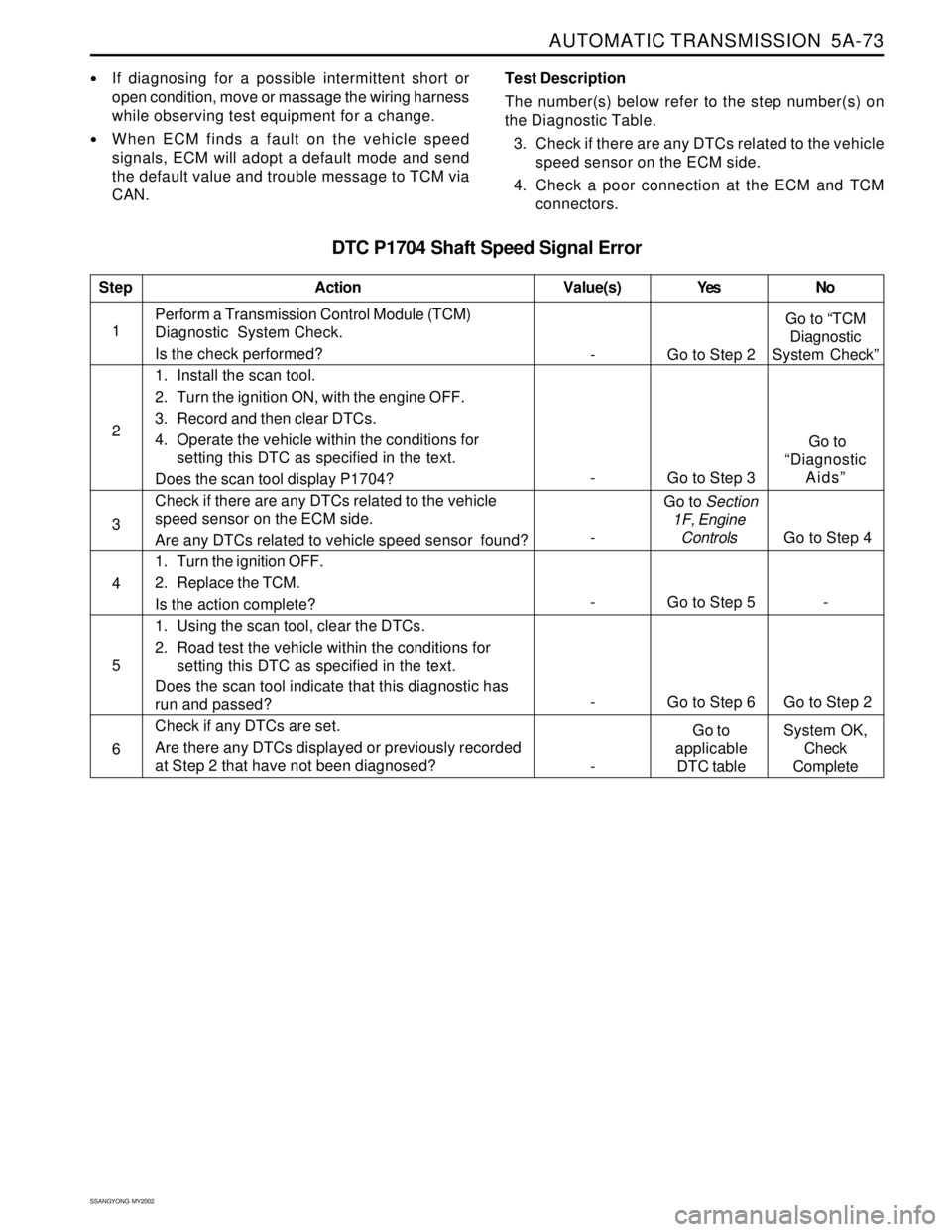
AUTOMATIC TRANSMISSION 5A-73
SSANGYONG MY2002
If diagnosing for a possible intermittent short or
open condition, move or massage the wiring harness
while observing test equipment for a change.
When ECM finds a fault on the vehicle speed
signals, ECM will adopt a default mode and send
the default value and trouble message to TCM via
CAN.Test Description
The number(s) below refer to the step number(s) on
the Diagnostic Table.
3. Check if there are any DTCs related to the vehicle
speed sensor on the ECM side.
4. Check a poor connection at the ECM and TCM
connectors.
DTC P1704 Shaft Speed Signal Error
1Perform a Transmission Control Module (TCM)
Diagnostic System Check.
Is the check performed?
1. Install the scan tool.
2. Turn the ignition ON, with the engine OFF.
3. Record and then clear DTCs.
4. Operate the vehicle within the conditions for
setting this DTC as specified in the text.
Does the scan tool display P1704?
Check if there are any DTCs related to the vehicle
speed sensor on the ECM side.
Are any DTCs related to vehicle speed sensor found?
1. Turn the ignition OFF.
2. Replace the TCM.
Is the action complete?
1. Using the scan tool, clear the DTCs.
2. Road test the vehicle within the conditions for
setting this DTC as specified in the text.
Does the scan tool indicate that this diagnostic has
run and passed?
Check if any DTCs are set.
Are there any DTCs displayed or previously recorded
at Step 2 that have not been diagnosed?
StepAction Value(s) Yes No
2
3
- Go to Step 5 - 4
- Go to Step 6 Go to Step 2 5
6
- Go to Step 2Go to “TCM
Diagnostic
System Check”
- Go to Step 3 Go to
“Diagnostic
Aids”
- Go to Section
1F, Engine
Controls
Go to Step 4
-Go to
applicable
DTC tableSystem OK,
Check
Complete
Page 1170 of 2053
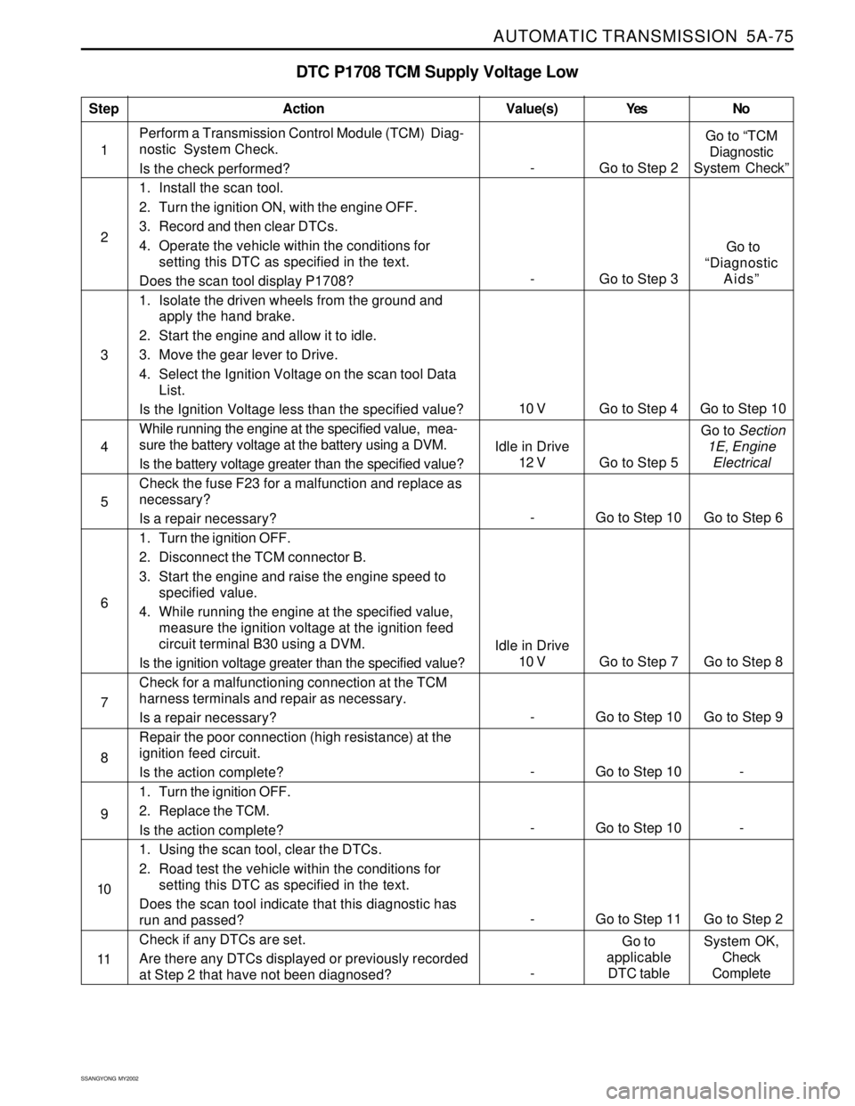
AUTOMATIC TRANSMISSION 5A-75
SSANGYONG MY2002
DTC P1708 TCM Supply Voltage Low
1Perform a Transmission Control Module (TCM) Diag-
nostic System Check.
Is the check performed?
1. Install the scan tool.
2. Turn the ignition ON, with the engine OFF.
3. Record and then clear DTCs.
4. Operate the vehicle within the conditions for
setting this DTC as specified in the text.
Does the scan tool display P1708?
1. Isolate the driven wheels from the ground and
apply the hand brake.
2. Start the engine and allow it to idle.
3. Move the gear lever to Drive.
4. Select the Ignition Voltage on the scan tool Data
List.
Is the Ignition Voltage less than the specified value?
While running the engine at the specified value, mea-
sure the battery voltage at the battery using a DVM.
Is the battery voltage greater than the specified value?
Check the fuse F23 for a malfunction and replace as
necessary?
Is a repair necessary?
1. Turn the ignition OFF.
2. Disconnect the TCM connector B.
3. Start the engine and raise the engine speed to
specified value.
4. While running the engine at the specified value,
measure the ignition voltage at the ignition feed
circuit terminal B30 using a DVM.
Is the ignition voltage greater than the specified value?
Check for a malfunctioning connection at the TCM
harness terminals and repair as necessary.
Is a repair necessary?
Repair the poor connection (high resistance) at the
ignition feed circuit.
Is the action complete?
1. Turn the ignition OFF.
2. Replace the TCM.
Is the action complete?
1. Using the scan tool, clear the DTCs.
2. Road test the vehicle within the conditions for
setting this DTC as specified in the text.
Does the scan tool indicate that this diagnostic has
run and passed?
Check if any DTCs are set.
Are there any DTCs displayed or previously recorded
at Step 2 that have not been diagnosed?
StepAction Value(s) Yes No
2
3
5
- Go to Step 10 Go to Step 9 6 4
- Go to Step 10 - 7
- Go to Step 10 - 8
- Go to Step 11 Go to Step 2 9
10
- Go to Step 2Go to “TCM
Diagnostic
System Check”
10 V Go to Step 4 Go to Step 10
- Go to Step 3 Go to
“Diagnostic
Aids”
11
-Go to
applicable
DTC tableSystem OK,
Check
Complete
- Go to Step 10 Go to Step 6
Idle in Drive
10 V Go to Step 7 Go to Step 8
Idle in Drive
12 V Go to Step 5 Go to Section
1E, Engine
Electrical
Page 1172 of 2053
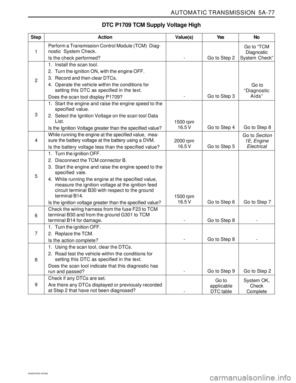
AUTOMATIC TRANSMISSION 5A-77
SSANGYONG MY2002
DTC P1709 TCM Supply Voltage High
1Perform a Transmission Control Module (TCM) Diag-
nostic System Check.
Is the check performed?
1. Install the scan tool.
2. Turn the ignition ON, with the engine OFF.
3. Record and then clear DTCs.
4. Operate the vehicle within the conditions for
setting this DTC as specified in the text.
Does the scan tool display P1709?
1. Start the engine and raise the engine speed to the
specified value.
2. Select the Ignition Voltage on the scan tool Data
List.
Is the Ignition Voltage greater than the specified value?
While running the engine at the specified value, mea-
sure the battery voltage at the battery using a DVM.
Is the battery voltage less than the specified value?
1. Turn the ignition OFF.
2. Disconnect the TCM connector B.
3. Start the engine and raise the engine speed to the
specified vale.
4. While running the engine at the specified value,
measure the ignition voltage at the ignition feed
circuit terminal B30 with respect to the ground
terminal B14.
Is the ignition voltage greater than the specified value?
Check the wiring harness from the fuse F23 to TCM
terminal B30 and from the ground G301 to TCM
terminal B14 for damage.
1. Turn the ignition OFF.
2. Replace the TCM.
Is the action complete?
1. Using the scan tool, clear the DTCs.
2. Road test the vehicle within the conditions for
setting this DTC as specified in the text.
Does the scan tool indicate that this diagnostic has
run and passed?
Check if any DTCs are set.
Are there any DTCs displayed or previously recorded
at Step 2 that have not been diagnosed?
StepAction Value(s) Yes No
2
3
5
6 4
- Go to Step 8 -
7
- Go to Step 8 -
8
- Go to Step 9 Go to Step 2
9
- Go to Step 2Go to “TCM
Diagnostic
System Check”
- Go to Step 3 Go to
“Diagnostic
Aids”
1500 rpm
16.5 V
Go to Step 6 Go to Step 7
1500 rpm
16.5 V Go to Step 4 Go to Step 8
2000 rpm
16.5 V Go to Step 5 Go to Section
1E, Engine
Electrical
-Go to
applicable
DTC tableSystem OK,
Check
Complete