Page 1484 of 2053

SSANGYONG MY2002
6C-16 POWER STEERING GEAR
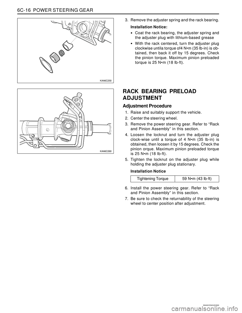
KAA6C250
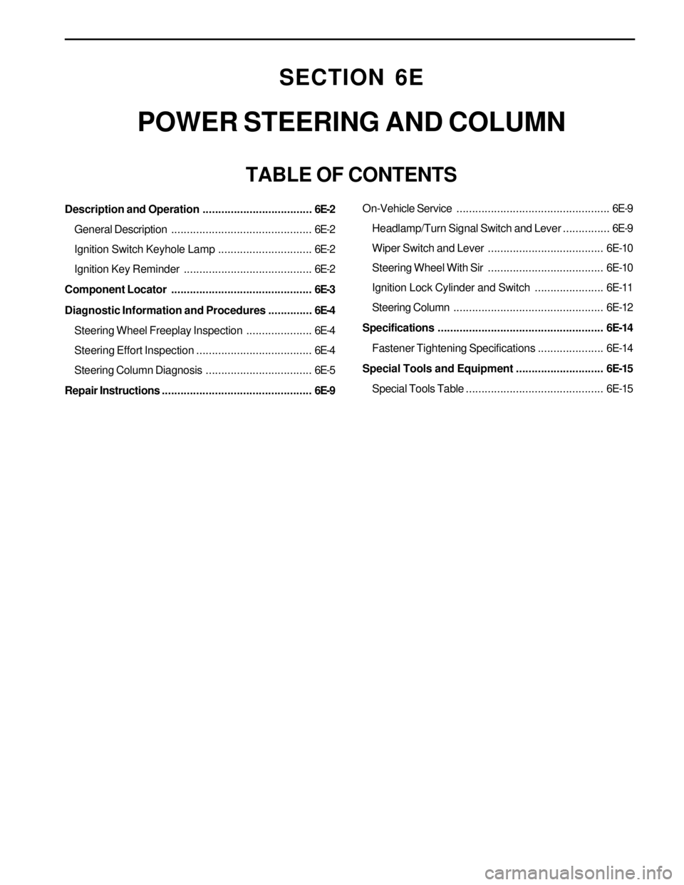
KAA6C260
3. Remove the adjuster spring and the rack bearing.
Installation Notice:
Coat the rack bearing, the adjuster spring and
the adjuster plug with lithium-based grease
With the rack centered, turn the adjuster plug
clockwise untila torque of4 Nm (35 lb-in) is ob-
tained, then back it off by 15 degrees. Check
the pinion torque. Maximum pinion preloaded
torque is 25 Nm (18 lb-ft).
RACK BEARING PRELOAD
ADJUSTMENT
Adjustment Procedure
1. Raise and suitably support the vehicle.
2. Center the steering wheel.
3. Remove the power steering gear. Refer to “Rack
and Pinion Assembly” in this section.
4. Loosen the locknut and turn the adjuster plug
clock-wise until a torque of 4 Nm (35 lb-in) is
obtained, then loosen it by 15 degrees. Check the
pinion orque. Maximum pinion preloaded torque
is 25 Nm (18 lb-ft).
5. Tighten the locknut on the adjuster plug while
holding the adjuster plug stationary.
Installation Notice
Tightening Torque 59 Nm (43 lb-ft)
6. Install the power steering gear. Refer to “Rack
and Pinion Assembly” in this section.
7. Be sure to check the returnability of the steering
wheel to center position after adjustment.
Page 1487 of 2053

SECTION 6E
POWER STEERING AND COLUMN
TABLE OF CONTENTS
Description and Operation...................................6E-2
General Description.............................................6E-2
Ignition Switch Keyhole Lamp..............................6E-2
Ignition Key Reminder .........................................6E-2
Component Locator.............................................6E-3
Diagnostic Information and Procedures..............6E-4
Steering Wheel Freeplay Inspection.....................6E-4
Steering Effort Inspection.....................................6E-4
Steering Column Diagnosis..................................6E-5
Repair Instructions................................................6E-9On-Vehicle Service.................................................6E-9
Headlamp/Turn Signal Switch and Lever...............6E-9
Wiper Switch and Lever.....................................6E-10
Steering Wheel With Sir.....................................6E-10
Ignition Lock Cylinder and Switch......................6E-11
Steering Column................................................6E-12
Specifications.....................................................6E-14
Fastener Tightening Specifications.....................6E-14
Special Tools and Equipment............................6E-15
Special Tools Table............................................6E-15
Page 1488 of 2053

SSANGYONG MY2002
6E-2 POWER STEERING AND COLUMN
GENERAL DESCRIPTION
Caution: To ensure the energy-absorbing action of
the steering column, it is important to use only the
specified screws, bolts, and nuts, tightened to the
specified torque.
In addition to the steering function, the steering column
provides safety and security.
The energy-absorbing column is designed to compress
in a front-end collision to lessen the chance of driver
injury.
The ignition switch and the lock are mounted on the
column, allowing the ignition and steering operations
to be locked to inhibit theft of the car.
The column levers trigger the turn signals, the headlight
beams, and the windshield washer and wipers.
A tilt steering column uses a spherical joint to allow
the steering wheel to tilt up and down. This enables
the driver to adjust the steering wheel to a comfortable
position.
Notice: Apply a thin coat of lithium grease to all friction
points when reassembling.
The column may be disassembled and reassembled
easily.
DESCRIPTION AND OPERATION
IGNITION SWITCH KEYHOLE LAMP
For description and lamp replacement information, Re-
fer to Section 9B, Lighting Systems.
IGNITION KEY REMINDER
The ignition key reminder alerts the driver that the key
is still in the ignition when the driver attempts to exit
the vehicle.
An internal switch in the ignition lock cylinder supplies
battery voltage to the reminder chime module when all
of the following conditions are true:
•The key is in the ignition switch.
The ignition is OFF.
The driver’s door is open.
For information on removal and installation of the re-
minder chime module, Refer to Section 9E, Instrumen-
tation/Driver Information.
Page 1489 of 2053
POWER STEERING AND COLUMN 6E-3
SSANGYONG MY2002
COMPONENT LOCATOR
KAA6E010
1 Driver Airbag Module
2 Steering Wheel Nut
3 Steering Wheel
4 Lower Steering Column Cover
5 Lower Steering Column Cover Screw
6 Steering Column Upper Mounting Bolt7 Steering Column Lower Mounting Nut
8 Intermediate Shaft Upper Pinch Bolt
9 Intermediate Shaft
10 Steering Column
11 Upper Steering Column Cover
12 Headlamp/Turn Signal Switch and Lever
Page 1490 of 2053
SSANGYONG MY2002
6E-4 POWER STEERING AND COLUMN
DIAGNOSTIC INFORMATION AND PROCEDURES
STEERING WHEEL FREEPLAY
INSPECTION
KAA6E020
Inspection Procedure
1. Start the engine and set the wheels in straight
ahead position.
2. Slightly move the steering wheel to the left and
right and measure steering wheel free play when
the front wheel is start to move.
Notice: If exceeds specification, the steering
column shaft connections and steering linkage
clearance. Replace or repair if necessary.
StandardMax. 30 mm
STEERING EFFORT INSPECTION
KAA6E030
Inspection Procedure
1. Place a vehicle on the paved flat ground with front
wheels in a straight ahead position.
2. Start the engine and run it at 1,000 rpm.
3. Using a scale, measure the steering effort in both
directions.
Notice : The difference in steering effort of left
and right should be within 0.6 kg.
StandardMax. 3.0 kg
Page 1492 of 2053

SSANGYONG MY2002
6E-6 POWER STEERING AND COLUMN
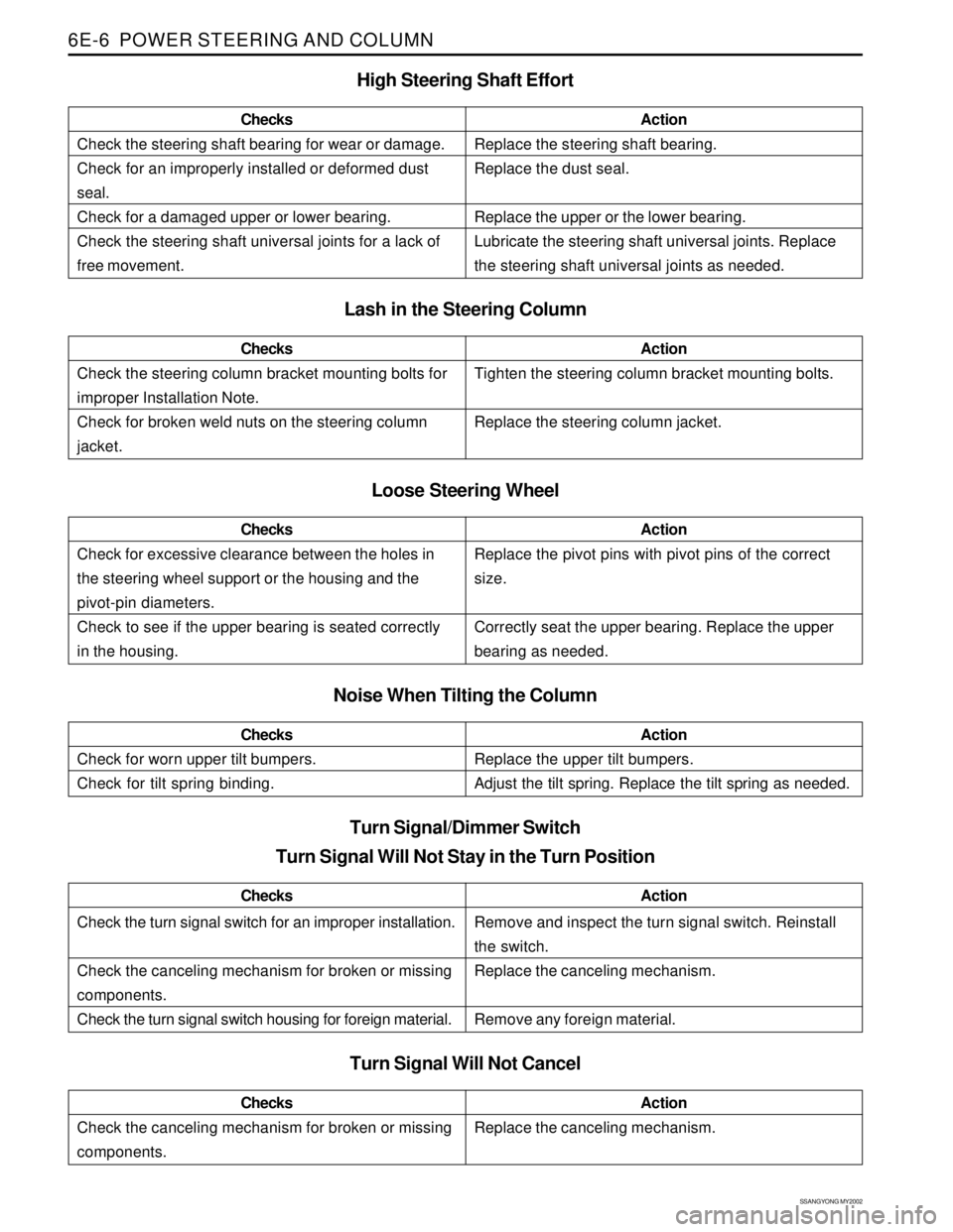
Check the steering shaft bearing for wear or damage.
Check for an improperly installed or deformed dust
seal.
Check for a damaged upper or lower bearing.
Check the steering shaft universal joints for a lack of
free movement.ChecksActionReplace the steering shaft bearing.
Replace the dust seal.
Replace the upper or the lower bearing.
Lubricate the steering shaft universal joints. Replace
the steering shaft universal joints as needed.
Lash in the Steering Column
Loose Steering Wheel
Check for excessive clearance between the holes in
the steering wheel support or the housing and the
pivot-pin diameters.
Check to see if the upper bearing is seated correctly
in the housing.ChecksActionReplace the pivot pins with pivot pins of the correct
size.
Correctly seat the upper bearing. Replace the upper
bearing as needed.
High Steering Shaft Effort
Check the steering column bracket mounting bolts for
improper Installation Note.
Check for broken weld nuts on the steering column
jacket.ChecksActionTighten the steering column bracket mounting bolts.
Replace the steering column jacket.
Noise When Tilting the Column
Check for worn upper tilt bumpers.
Check for tilt spring binding.ChecksActionReplace the upper tilt bumpers.
Adjust the tilt spring. Replace the tilt spring as needed.
Check the turn signal switch for an improper installation.
Check the canceling mechanism for broken or missing
components.
Check the turn signal switch housing for foreign material.ChecksActionRemove and inspect the turn signal switch. Reinstall
the switch.
Replace the canceling mechanism.
Remove any foreign material.
Turn Signal/Dimmer Switch
Turn Signal Will Not Stay in the Turn Position
Turn Signal Will Not Cancel
Check the canceling mechanism for broken or missing
components.ChecksActionReplace the canceling mechanism.
Page 1496 of 2053
SSANGYONG MY2002
6E-10 POWER STEERING AND COLUMN
KAA6E060
KAA6E080
KAA6E070
WIPER SWITCH AND LEVER
Removal and Installation Procedure
1. Disconnect the negative battery cable.
2. Remove the upper and the lower steering column
cover screws.
3. Remove the upper and the lower steering column
cover.
4. Remove the wiper switch and lever mounting
mounting screws.
Tightening Torque 65 Nm (48 lb-ft) 5. Disconnect the wiper switch and lever connector.
6. Remove the wiper switch and lever.
STEERING WHEEL WITH SIR
Tools Required
661 589 00 33 00 Steering Wheel Puller
Removal and Installation Procedure
1. Disconnect the negative battery cable.
2. Remove the SIR module. Refer to Section 8B, Sup-
plemental Inflatable Restraints.
3. Remove the steering wheel nut.
Removal Notice:
In order to install the steering wheel correctly,
match mark the steering column shaft to the
steering wheel.
Installation Notice
Page 1497 of 2053
POWER STEERING AND COLUMN 6E-11
SSANGYONG MY2002
KAA6E040
KAA6E100
KAA6E090
4. Remove the steering wheel using the steering
wheel puller 661 589 00 33 00.
Installation Notice:
Align the match marks on the steering wheel
and the steering column shaft.
IGNITION LOCK CYLINDER AND
SWITCH
Removal and Installation Procedure
1. Disconnect the negative battery cable.
2. Remove the upper and the lower steering column
cover screws.
3. Remove the upper and the lower steering column
cover.
4. Remove the screws for illumination keyhole
connection.
5. With the key in the ignition turned to the position
designated ACC, remove the lock cylinder by
pressing down the detent spring with a 2.5 mm
allen wrench or other suitable tool, and pulling the
lock cylinder out of the cylinder housing.