1997 SSANGYONG KORANDO wheel
[x] Cancel search: wheelPage 1498 of 2053
SSANGYONG MY2002
6E-12 POWER STEERING AND COLUMN
KAA6E040
KAA6E120
STEERING COLUMN
Important: Remove the steering column only if the
following conditions exist:
The steering column requires replacement.
The steering and the ignition lock housing require
replacement.
Another operation requires the removal of the
steering column
Notice: The steering column is extremely
susceptible to damage after it has been removed
from the vehicle. Dropping the column assembly
on its end or hammering the end of the steering
shaft can collapse the steering shaft or loosen the
plastic injections which maintain column rigidity.
Leaning on the column can cause it to bend or
deform. Any of the above damage can impair the
column’s collapsible design. If it is necessary to
remove the steering wheel, use only the specified
steering wheel puller.
Removal and Installation Procedure
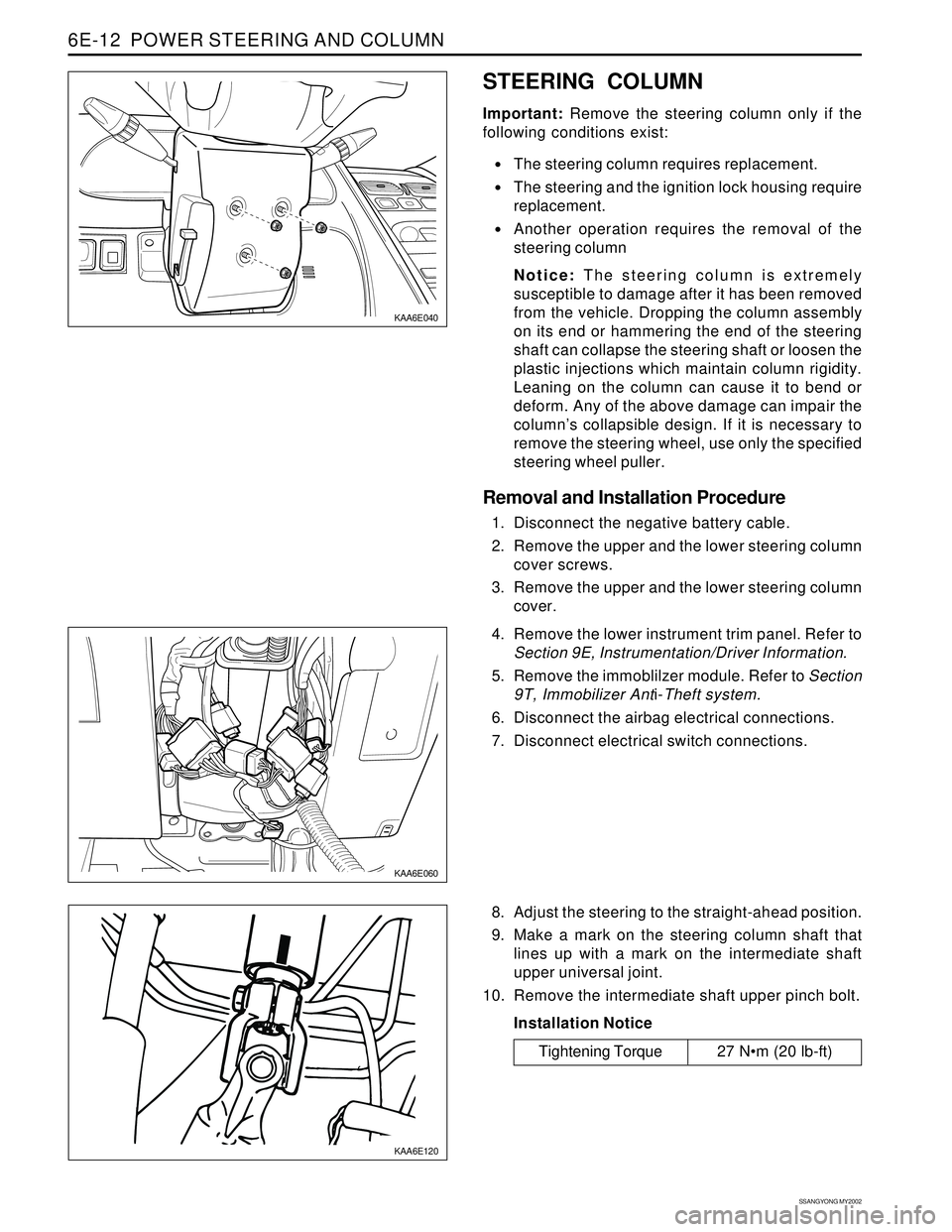
1. Disconnect the negative battery cable.
2. Remove the upper and the lower steering column
cover screws.
3. Remove the upper and the lower steering column
cover.
KAA6E060
4. Remove the lower instrument trim panel. Refer to
Section 9E, Instrumentation/Driver Information.
5. Remove the immoblilzer module. Refer to Section
9T, Immobilizer Anti-Theft system.
6. Disconnect the airbag electrical connections.
7. Disconnect electrical switch connections.
8. Adjust the steering to the straight-ahead position.
9. Make a mark on the steering column shaft that
lines up with a mark on the intermediate shaft
upper universal joint.
10. Remove the intermediate shaft upper pinch bolt.
Installation Notice
Tightening Torque 27 Nm (20 lb-ft)
Page 1500 of 2053
SSANGYONG MY2002
6E-14 POWER STEERING AND COLUMN
SPECIFICATIONS
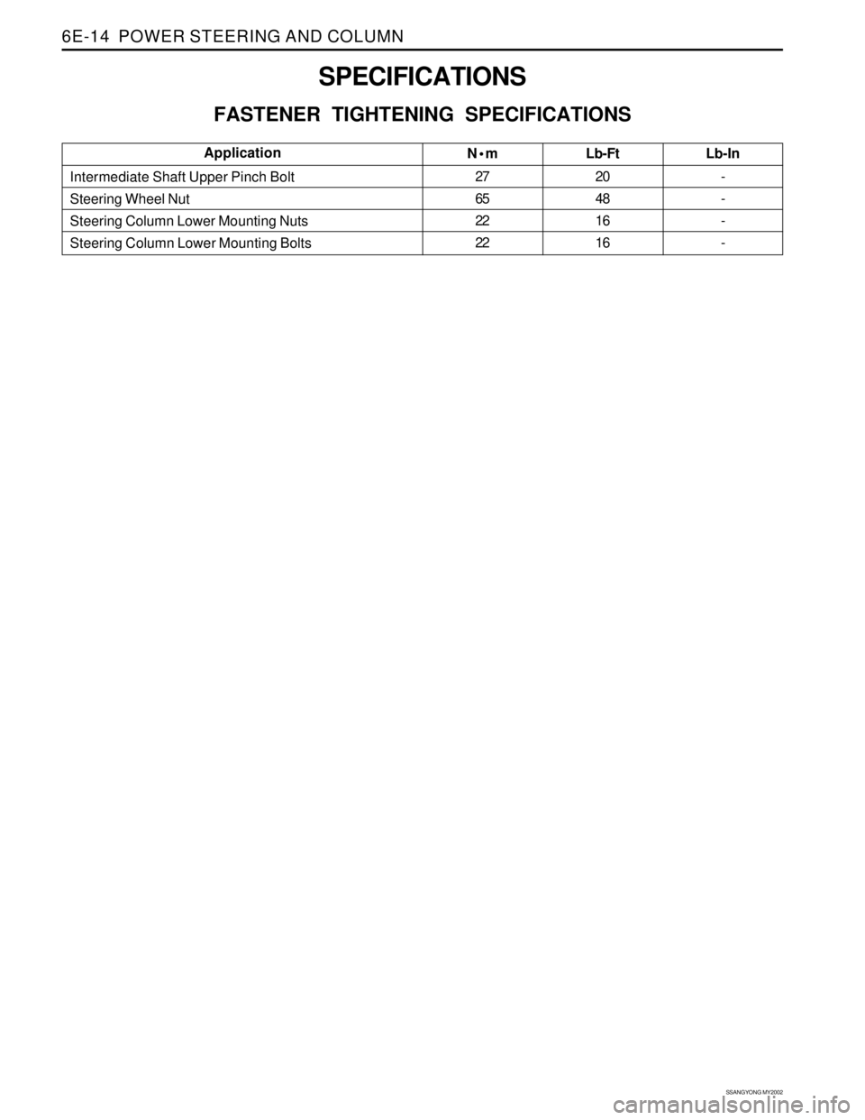
FASTENER TIGHTENING SPECIFICATIONS
N•m
27
65
22
22Lb-Ft
20
48
16
16 Intermediate Shaft Upper Pinch Bolt
Steering Wheel Nut
Steering Column Lower Mounting Nuts
Steering Column Lower Mounting BoltsLb-In
-
-
-
-Application
Page 1501 of 2053
POWER STEERING AND COLUMN 6E-15
SSANGYONG MY2002
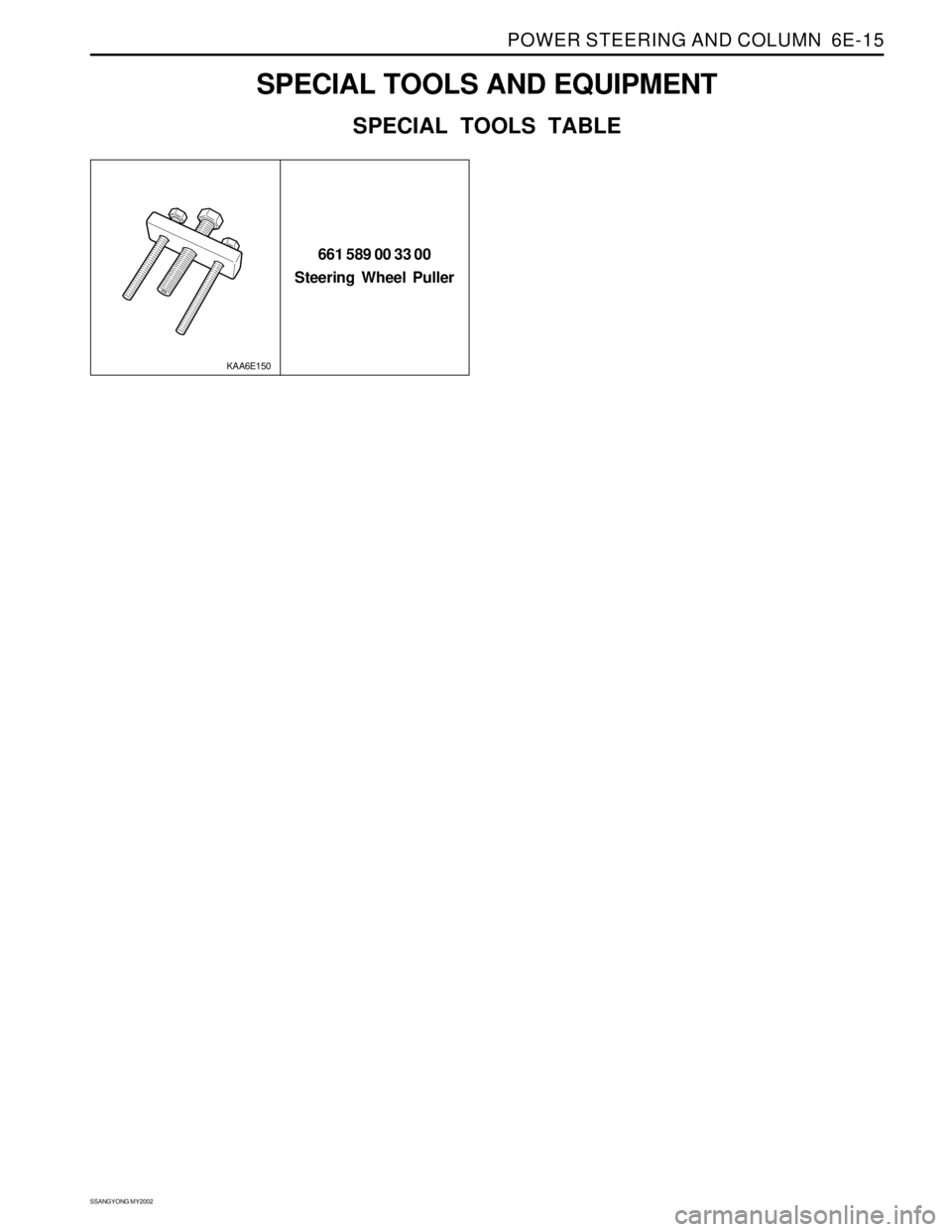
SPECIAL TOOLS AND EQUIPMENT
SPECIAL TOOLS TABLE
661 589 00 33 00
Steering Wheel Puller
KAA6E150
Page 1588 of 2053
SUPPLEMENTAL RESTRAINTS SYSTEM 8B-3
SSANGYONG MY2002
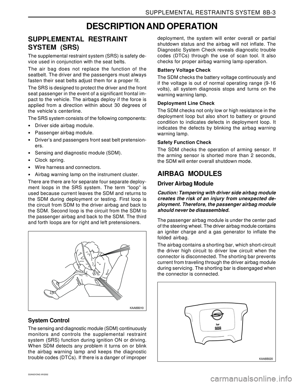
SUPPLEMENTAL RESTRAINT
SYSTEM (SRS)
The supplemental restraint system (SRS) is safety de-
vice used in conjunction with the seat belts.
The air bag does not replace the function of the
seatbelt. The driver and the passengers must always
fasten their seat belts adjust them for a proper fit.
The SRS is designed to protect the driver and the front
seat passenger in the event of a significant frontal im-
pact to the vehicle. The airbags deploy if the force is
applied from a direction within about 30 degrees of
the vehicle’s centerline.
The SRS system consists of the following components:
Driver side airbag module.
Passenger airbag module.
Driver’s and passengers front seat belt pretension-
ers.
Sensing and diagnostic module (SDM).
Clock spring.
Wire harness and connectors.
Airbag warning lamp on the instrument cluster.
There are there are for separate four separate deploy-
ment loops in the SRS system. The term “loop” is
used because current leaves the SDM and returns to
the SDM during deployment or testing. First loop is
the circuit from SDM to the driver airbag and back to
the SDM. Second loop is the circuit from the SDM to
the passenger airbag and back to the SDM. The third
and forth loops are for right and left pretensioners.
DESCRIPTION AND OPERATION
KAA8B010
deployment, the system will enter overall or partial
shutdown status and the airbag will not inflate. The
Diagnostic System Check reveals diagnostic trouble
codes (DTCs) through the use of scan tool. It also
checks for proper airbag warning lamp operation.
Battery Voltage Check
The SDM checks the battery voltage continuously and
if the voltage is out of normal operating range (9-16
volts), all system diagnosis stops and turns on the
warning warning lamp.
Deployment Line Check
The SDM checks not only low or high resistance in the
deployment loop but also short to battery or ground
condition to indicates defects in deployment loop. It
indicates the defects by blinking the airbag warning
warning lamp.
Safety Function Check
The SDM checks the operation of arming sensor. If
the arming sensor is shorted more than 2 seconds,
the SDM will enter overall shutdown mode.
AIRBAG MODULES
Driver Airbag Module
Caution: Tampering with driver side airbag module
creates the risk of an injury from unexpected de-
ployment. Therefore, the passenger airbag module
should never be disassembled.
The passenger airbag module is under the center pad
of the steering wheel. The driver airbag module contains
an igniter charge and a gas generator to inflate the
folded airbag.
The airbag contains a shorting bar, which short-circuit
the driver high circuit to driver low circuit when the
connector is disconnected. The shorting bar prevents
current from traveling through the driver airbag module
during servicing. The shorting bar is disengaged when
the connector is connected.
System Control
The sensing and diagnostic module (SDM) continuously
monitors and controls the supplemental restraint
system (SRS) function during ignition ON or driving.
When SDM detects any problem it turns on or blink
the airbag warning lamp and keeps the diagnostic
trouble codes (DTCs). If there is a danger of improper
KAA8B020
Page 1590 of 2053
SUPPLEMENTAL RESTRAINTS SYSTEM 8B-5
SSANGYONG MY2002
KAA8B060
AIRBAG WARNING LAMP
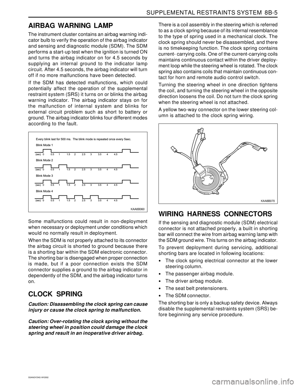
The instrument cluster contains an airbag warning indi-
cator bulb to verify the operation of the airbag indicator
and sensing and diagnostic module (SDM). The SDM
performs a start-up test when the ignition is turned ON
and turns the airbag indicator on for 4.5 seconds by
supplying an internal ground to the indicator lamp
circuit. After 4.5 seconds, the airbag indicator will turn
off if no more malfunctions have been detected.
If the SDM has detected malfunctions, which could
potentially affect the operation of the supplemental
restraint system (SRS) it turns on or blinks the airbag
warning indicator. The airbag indicator stays on for
the malfunction of internal system and blinks for
external circuit problem such as short to battery or
ground. The airbag indicator blinks four different modes
according to the fault.
Some malfunctions could result in non-deployment
when necessary or deployment under conditions which
would no normally result in deployment.
When the SDM is not properly attached to its connector
the airbag circuit is shorted to ground because there
is a shorting bar within the SDM electronic connector.
The shorting bar is disengaged when proper connection
is made, but if a poor connection exists the SDM
connector supplies a ground to the airbag indicator in
dependently of the SDM, and the airbag indicator turns
on.
CLOCK SPRING
Caution: Disassembling the clock spring can cause
injury or cause the clock spring to malfunction.
Caution: Over-rotating the clock spring without the
steering wheel in position could damage the clock
spring and result in an inoperative driver airbag.There is a coil assembly in the steering which is referred
to as a clock spring because of its internal resemblance
to the type of spring used in a mechanical clock. The
clock spring should never be disassembled, and there
is no timekeeping function. The clock spring contains
current- carrying coils. One of the current-carrying coils
maintains continuous contact within the driver deploy-
ment loop while the steering wheel is rotated. The clock
spring also contains coils that maintain continuous con-
tact for horn and remote audio control switch.
Turning the steering wheel in one direction tightens
the coil, and turning the steering wheel in the opposite
direction loosens the coil. Do not turn the clock spring
when the steering wheel is not attached.
A yellow two-way connector on the lower steering col-
umn is attached to the clock spring wiring.
WIRING HARNESS CONNECTORS
If the sensing and diagnostic module (SDM) electrical
connector is not attached properly, a built in shorting
bar will connect the wire from airbag warning lamp with
the SDM ground wire. This turns on the airbag indicator.
To prevent deployment during servicing, additional
shorting bars are located in following locations:
The clock spring electrical connector at the lower
steering column.
The passenger airbag module.
The driver airbag module.
The seat belt pretensioners.
The SDM connector.
The shorting bar is only a backup safety device. Always
disable the supplemental restraints system (SRS) be-
fore beginning any service procedure.
KAA8B070
Page 1640 of 2053
SSANGYONG MY2002
8B-58 SUPPLEMENTAL RESTRAINTS SYSTEM
REPAIR INSTRUCTION
ON-VEHICLE SERVICE
SERVICE PRECAUTION
Caution: The sensing and diagnosis module (SDM)
can maintain sufficient voltage to deploy the airbags
and pretensioner for 0.15 seconds after the ignition
is OFF and the airbag fuse has been removed. If the
airbags or pretensioners are not disconnected, do
not begin service until one minute has passed after
disconnecting power to the SDM. If the airbag are
disconnected, service can begin immediately without
waiting for one-minute time period to expire. Failure
to temporarily disable the SRS during service can
result in unexpected deployment, personal injury,
and otherwise unneeded SRS repairs.
DISABLING THE SUPPLEMENTAL
RESTRAINT SYSTEM (SRS)
1. Turn the steering wheel to the straight-ahead
position.
2. Turn the ignition switch to LOCK and remove the key.
3. Remove the airbag fuse F31 in the I/P fuse block
and wait more than one minute for SRS capacitor to
discharge.
ENABLING THE SUPPLEMENTAL
RESTRAINT SYSTEM (SRS)
Enabling the supplemental restraint system (SRS) is
reverse order of “Disabling the Supplemental Restraint
System (SRS)”.
Caution: Staying well away from the inflator
modules, turn the ignition key switch to ON, and
verify that the airbag indicator illuminates for 4.5
seconds and turns OFF. If it does not operate as
described, perform the “SRS Diagnostic System
Check” referring in this section.
HANDLING, INSTALLATION AND
DIAGNOSIS
Airbag modules should not be subjected to
temperature above 65°C (149°F)
An airbag module or sensing and diagnostic module
(SDM) should not be used if it has been dropped
from height of 0.9 meters (3 feet) or greater.
It is very important for the SDM to be installed flat
on the mounting surface, parallel to the vehicle’s
longitudinal axis.
To avoid setting diagnostic trouble codes (DTCs),
do not apply power to the SRS unless all components
are connected or a diagnostic chart request it.
The SRS Diagnostic System Check must be the
starting point of any SRS diagnostics. The SRS
Diagnostic System Check will verify proper airbag
indicator operation and will lead you to correct chart
to diagnose any SRS malfunctions. Bypassing
these procedures may result in extended diagnostic
time and incorrect parts replacements.
REPAIRS AND INSPECTIONS
REQUIRED AFTER AN ACCIDENT
Caution: any repairs to the vehicle’s structure must
return it to the original production configuration.
Deployment requires replacement of SDM, the
inflator modules, and a dimensional inspection of
the steering column.
If any SRS components are damaged, they must
be replaced. If SRS components mounting points
are damaged, they must be repaired or replaced.
Never use SRS parts from another vehicle. This does
not include remanufactured parts purchased from
an authorized source.
Do not attempt to service the SDM, the clock spring,
or other airbag modules, these items must be
replaced if they are defective.
Verify the part number of replacement airbag
modules. Some inflator modules look identical but
contain different internal components.
ACCIDENT WITH DEPLOYMENT -
COMPONENTS REPLACEMENT
All SRS components must be replaced after frontal crash
involving airbag deployment. After deployment, a
powdery residue may be on the surface of the airbag.
The powder consists primarily of cornstarch (used to
lubricate the bag as it inflates) and by-products of the
chemical reaction. Sodium hydroxide dust (similar to
lye soap) is produced as a by-product of the deployment
reaction. The sodium hydroxide then quickly reacts with
atmospheric moisture and is converted to sodium
carbonate and sodium bicarbonate (also known as
baking soda). Therefore, it is unlikely that sodium
hydroxide will be present after deployment. Replace
the following SRS components.
Caution: Wear gloves and safety glasses during the
disposal procedure. Refer to “Deployed Airbag
Module Disposal Procedure” in this section.
The SDM.
Airbag modules and pretensioners
SRS wiring
Clock spring
Page 1642 of 2053

SSANGYONG MY2002
8B-60 SUPPLEMENTAL RESTRAINTS SYSTEM
KAA8B140
DRIVER AIRBAG MODULE
Removal and installation Procedure
1. Disconnect the negative battery cable.
Caution: The SDM can maintain sufficient
voltage to deploy the airbags for 0.15 seconds
after the Ignition is OFF and the airbag fuse has
been removed. If the airbags are not
disconnected, service cannot begin until one
minute has passed after disconnecting power
to the SDM. If the airbags are disconnected,
service can begin immediately without waiting
for one-minute time period to expire. Failure to
temporarily disable the SRS during service
result in unexpected deployment, personal
injury, and otherwise unneeded SRS repair.
2. Disable the supplemental restraint system (SRS).
Refer to “Disabling the SRS” in this section.
3. Position the steering wheel straight ahead.
4. Remove the driver airbag module mounting bolts.
Installation Notice
Caution: When handling an airbag module,
always keeps the top of the unit facing upward.
This leaves room for the airbag to expand if the
module unexpectedly deploys. Without room
for expansion, a module suddenly propelled
toward a person or object can cause injury or
vehicle damage.
5. Remove the connector from the horn terminal and
the driver airbag module.
6. Remove the driver airbag module.
7. Installation should follow the removal procedure
in the reverse order.
Tightening Torque 8 Nm (71 lb-in)
Page 1643 of 2053
SUPPLEMENTAL RESTRAINTS SYSTEM 8B-61
SSANGYONG MY2002
KAA8B050
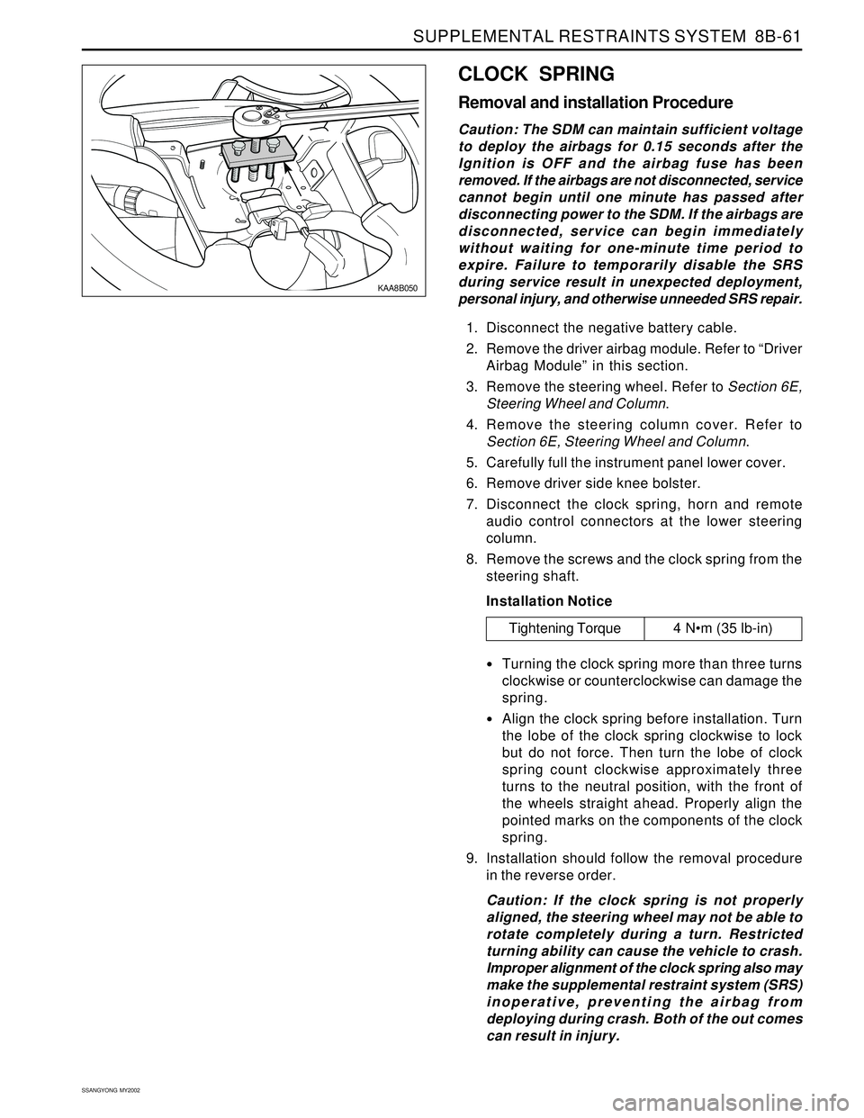
CLOCK SPRING
Removal and installation Procedure
Caution: The SDM can maintain sufficient voltage
to deploy the airbags for 0.15 seconds after the
Ignition is OFF and the airbag fuse has been
removed. If the airbags are not disconnected, service
cannot begin until one minute has passed after
disconnecting power to the SDM. If the airbags are
disconnected, service can begin immediately
without waiting for one-minute time period to
expire. Failure to temporarily disable the SRS
during service result in unexpected deployment,
personal injury, and otherwise unneeded SRS repair.
1. Disconnect the negative battery cable.
2. Remove the driver airbag module. Refer to “Driver
Airbag Module” in this section.
3. Remove the steering wheel. Refer to Section 6E,
Steering Wheel and Column.
4. Remove the steering column cover. Refer to
Section 6E, Steering Wheel and Column.
5. Carefully full the instrument panel lower cover.
6. Remove driver side knee bolster.
7. Disconnect the clock spring, horn and remote
audio control connectors at the lower steering
column.
8. Remove the screws and the clock spring from the
steering shaft.
Installation Notice
Turning the clock spring more than three turns
clockwise or counterclockwise can damage the
spring.
Align the clock spring before installation. Turn
the lobe of the clock spring clockwise to lock
but do not force. Then turn the lobe of clock
spring count clockwise approximately three
turns to the neutral position, with the front of
the wheels straight ahead. Properly align the
pointed marks on the components of the clock
spring.
9. Installation should follow the removal procedure
in the reverse order.
Caution: If the clock spring is not properly
aligned, the steering wheel may not be able to
rotate completely during a turn. Restricted
turning ability can cause the vehicle to crash.
Improper alignment of the clock spring also may
make the supplemental restraint system (SRS)
inoperative, preventing the airbag from
deploying during crash. Both of the out comes
can result in injury.
Tightening Torque 4 Nm (35 lb-in)