Page 1254 of 2053
5A-156 AUTOMATIC TRANSMISSION
SSANGYONG MY2002
DTC P1747 Solenoid 7 Circuit Short (Cont’d)
Check for a poor connection at the 10-way transmission
connector and TCM connector and repair the malfunc-
tioning terminals as necessary.
Is a repair necessary?
1. Turn the ignition OFF.
2. Replace the TCM.
Is the action complete?
1. Using the scan tool, clear the DTCs.
2. Road test the vehicle within the conditions for
setting this DTC as specified in the text.
Does the scan tool indicate that this diagnostic has
run and passed?
Check if any DTCs are set.
Are there any DTCs displayed or previously recorded
at Step 2 that have not been diagnosed?
StepAction Value(s) Yes No
10
- Go to Step 12 Go to Step 11
13 11
- Go to Step 12 -
12
- Go to Step 13 Go to Step 2
-Go to
applicable
DTC tableSystem OK,
Check
Complete
Page 1384 of 2053

SSANGYONG MY2002
5D1-14 TRANSFER CASE
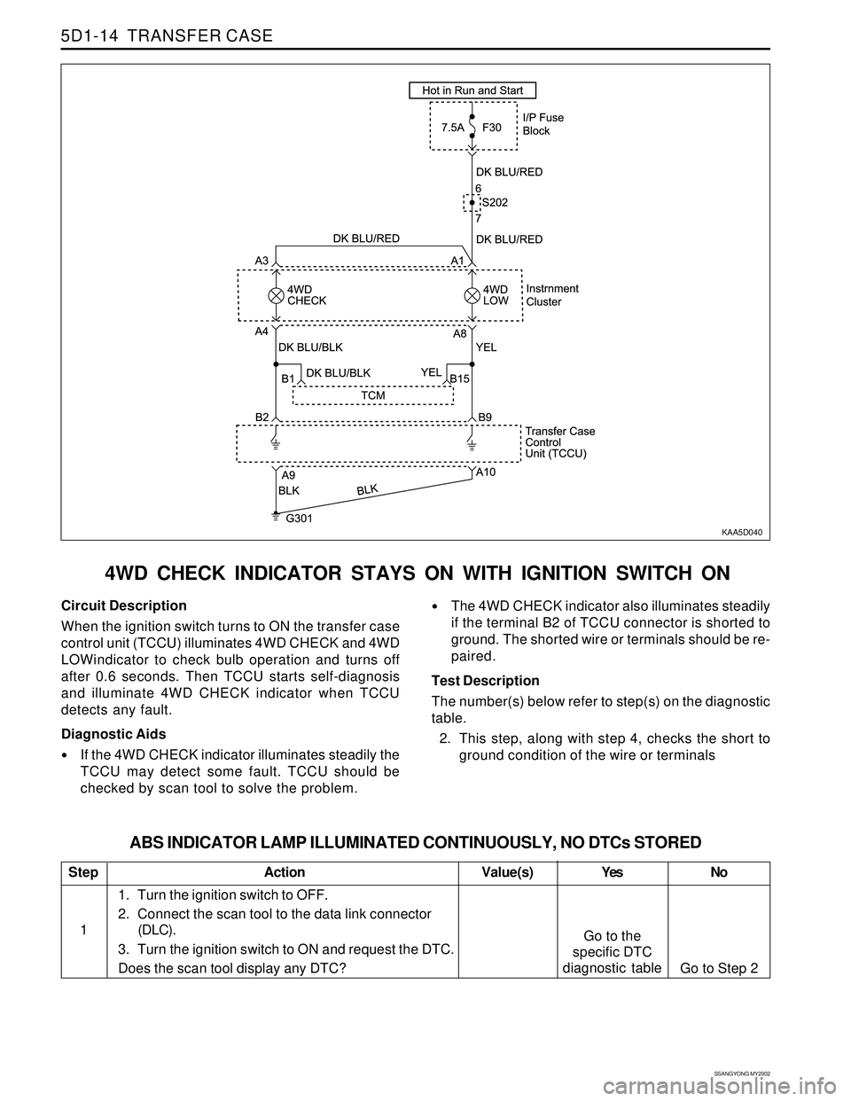
4WD CHECK INDICATOR STAYS ON WITH IGNITION SWITCH ON
KAA5D040
Circuit Description
When the ignition switch turns to ON the transfer case
control unit (TCCU) illuminates 4WD CHECK and 4WD
LOWindicator to check bulb operation and turns off
after 0.6 seconds. Then TCCU starts self-diagnosis
and illuminate 4WD CHECK indicator when TCCU
detects any fault.
Diagnostic Aids
If the 4WD CHECK indicator illuminates steadily the
TCCU may detect some fault. TCCU should be
checked by scan tool to solve the problem.
The 4WD CHECK indicator also illuminates steadily
if the terminal B2 of TCCU connector is shorted to
ground. The shorted wire or terminals should be re-
paired.
Test Description
The number(s) below refer to step(s) on the diagnostic
table.
2. This step, along with step 4, checks the short to
ground condition of the wire or terminals
Step
1
ABS INDICATOR LAMP ILLUMINATED CONTINUOUSLY, NO DTCs STORED
Action Yes
Go to the
specific DTC
diagnostic tableNo
Go to Step 2 Value(s)
1. Turn the ignition switch to OFF.
2. Connect the scan tool to the data link connector
(DLC).
3. Turn the ignition switch to ON and request the DTC.
Does the scan tool display any DTC?
Page 1411 of 2053

TRANSFER CASE (PART TIME - 4408) 5D2-11
SSANGYONG MY2002
KAA5D080
KAA5D090
KAA5D100
SELF-DIAGNOSIS TEST
System Description
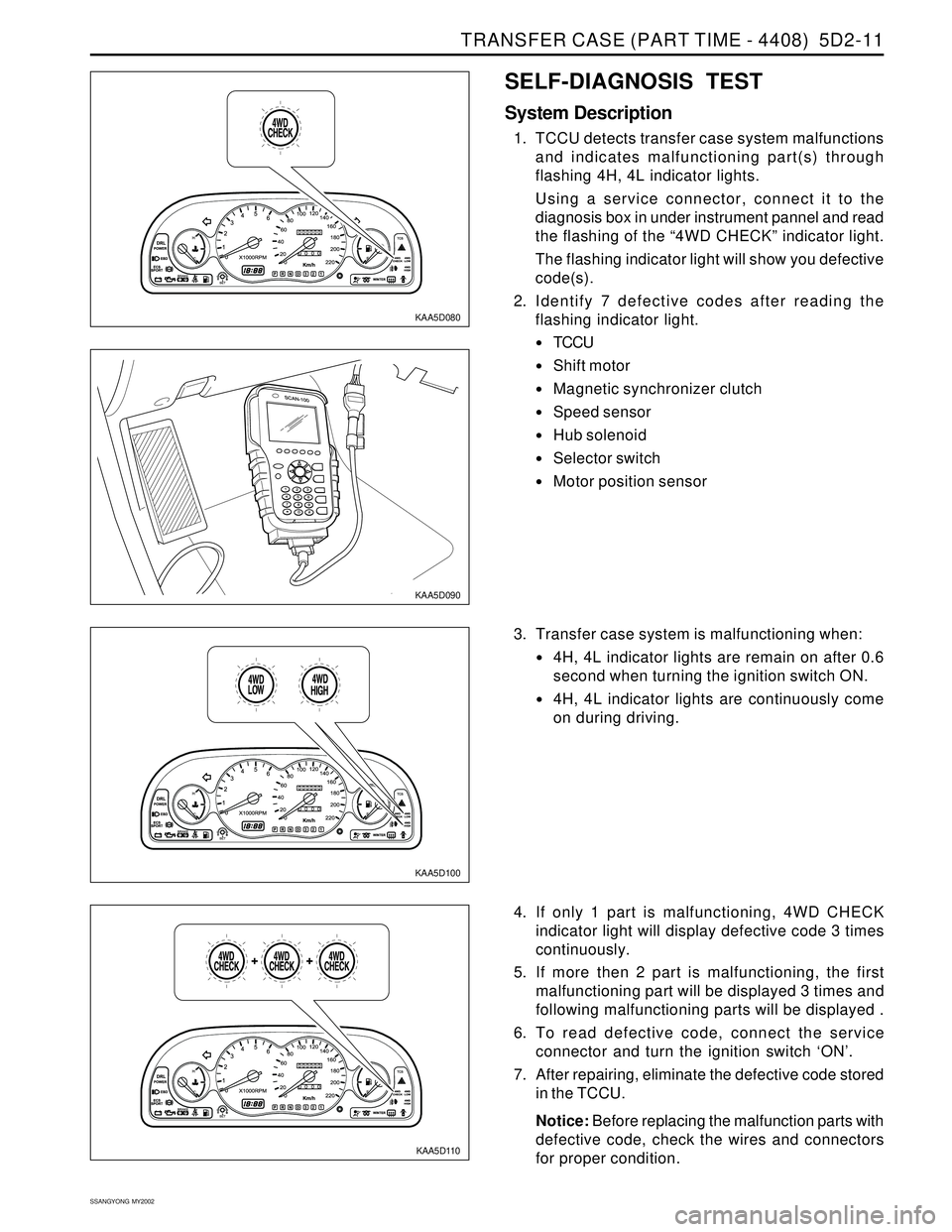
1. TCCU detects transfer case system malfunctions
and indicates malfunctioning part(s) through
flashing 4H, 4L indicator lights.
Using a service connector, connect it to the
diagnosis box in under instrument pannel and read
the flashing of the “4WD CHECK” indicator light.
The flashing indicator light will show you defective
code(s).
2. Identify 7 defective codes after reading the
flashing indicator light.
TCCU
Shift motor
Magnetic synchronizer clutch
Speed sensor
Hub solenoid
Selector switch
Motor position sensor
KAA5D110
3. Transfer case system is malfunctioning when:
4H, 4L indicator lights are remain on after 0.6
second when turning the ignition switch ON.
4H, 4L indicator lights are continuously come
on during driving.
4. If only 1 part is malfunctioning, 4WD CHECK
indicator light will display defective code 3 times
continuously.
5. If more then 2 part is malfunctioning, the first
malfunctioning part will be displayed 3 times and
following malfunctioning parts will be displayed .
6. To read defective code, connect the service
connector and turn the ignition switch ‘ON’.
7. After repairing, eliminate the defective code stored
in the TCCU.
Notice: Before replacing the malfunction parts with
defective code, check the wires and connectors
for proper condition.
Page 1413 of 2053
TRANSFER CASE (PART TIME - 4408) 5D2-13
SSANGYONG MY2002
Diagnostic Table
Connect a service connector. If turn the ignition switch
“ON” “4WD CHECK” indicator light will come on for
0.6 second and turn off for 3 seconds and then display
a defective code 3 times continuously.
4WD CHECK
Light
ON
OFF
4WD CHECK
Light
ON
OFF
4WD CHECK
Light
ON
OFF
4WD CHECK
Light
ON
OFF
4WD CHECK
Light
ON
OFFTCCU
Shift Motor
Synchronizer Clutch
Speed Sensor
Locking Hub Solenoid Defective Code No.
1
2
3
4
5
Malfunctioning Part
KAA5D140
KAA5D150
KAA5D160
KAA5D170
KAA5D180
Page 1562 of 2053

SSANGYONG MY2002
7D-8 FATC-HAVC
FUNCTION DESCRIPTION
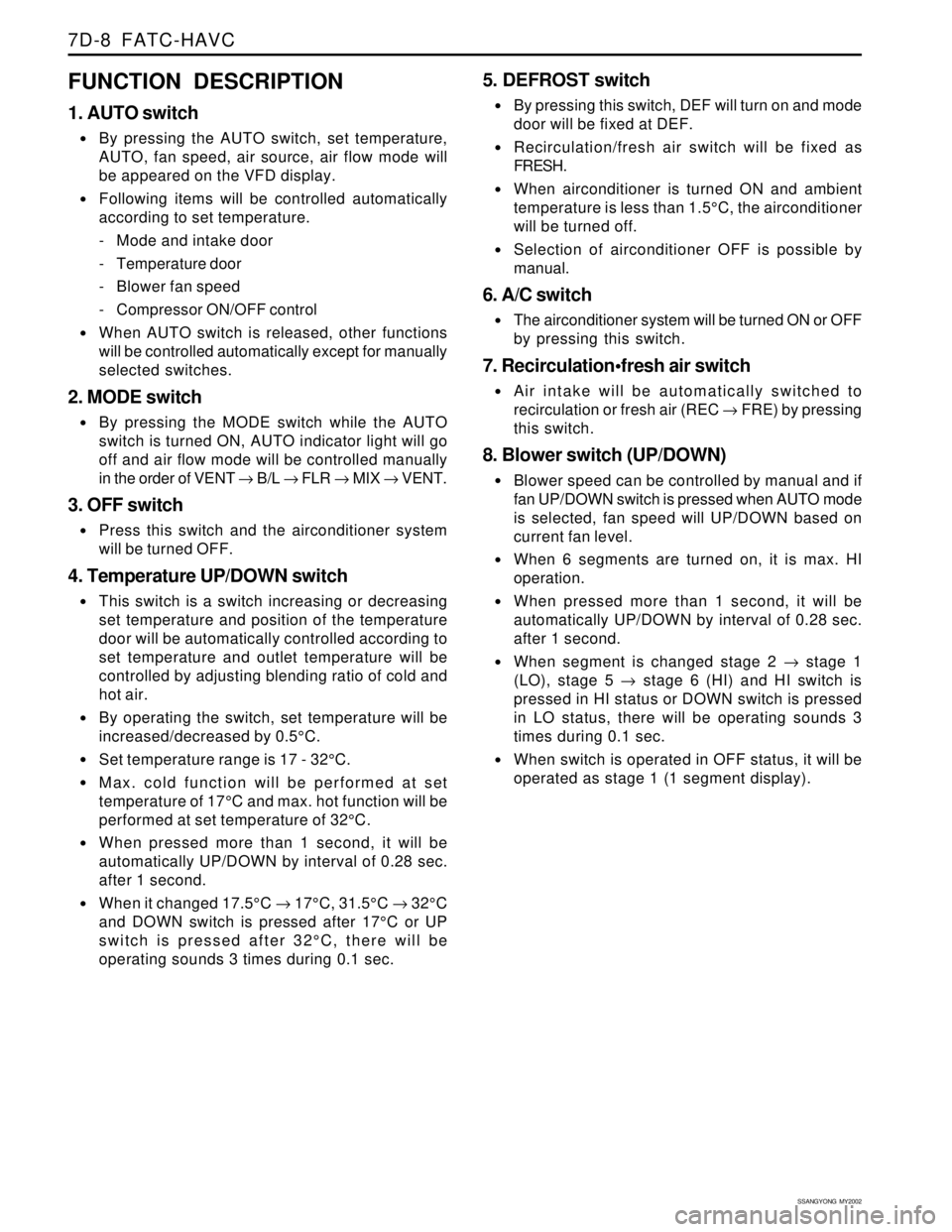
1. AUTO switch
By pressing the AUTO switch, set temperature,
AUTO, fan speed, air source, air flow mode will
be appeared on the VFD display.
Following items will be controlled automatically
according to set temperature.
- Mode and intake door
- Temperature door
- Blower fan speed
- Compressor ON/OFF control
When AUTO switch is released, other functions
will be controlled automatically except for manually
selected switches.
2. MODE switch
By pressing the MODE switch while the AUTO
switch is turned ON, AUTO indicator light will go
off and air flow mode will be controlled manually
in the order of VENT → B/L → FLR → MIX → VENT.
3. OFF switch
Press this switch and the airconditioner system
will be turned OFF.
4. Temperature UP/DOWN switch
This switch is a switch increasing or decreasing
set temperature and position of the temperature
door will be automatically controlled according to
set temperature and outlet temperature will be
controlled by adjusting blending ratio of cold and
hot air.
By operating the switch, set temperature will be
increased/decreased by 0.5°C.
Set temperature range is 17 - 32°C.
Max. cold function will be performed at set
temperature of 17°C and max. hot function will be
performed at set temperature of 32°C.
When pressed more than 1 second, it will be
automatically UP/DOWN by interval of 0.28 sec.
after 1 second.
When it changed 17.5°C → 17°C, 31.5°C → 32°C
and DOWN switch is pressed after 17°C or UP
switch is pressed after 32°C, there will be
operating sounds 3 times during 0.1 sec.
5. DEFROST switch
By pressing this switch, DEF will turn on and mode
door will be fixed at DEF.
Recirculation/fresh air switch will be fixed as
FRESH.
When airconditioner is turned ON and ambient
temperature is less than 1.5°C, the airconditioner
will be turned off.
Selection of airconditioner OFF is possible by
manual.
6. A/C switch
The airconditioner system will be turned ON or OFF
by pressing this switch.
7. Recirculationfresh air switch
Air intake will be automatically switched to
recirculation or fresh air (REC → FRE) by pressing
this switch.
8. Blower switch (UP/DOWN)
Blower speed can be controlled by manual and if
fan UP/DOWN switch is pressed when AUTO mode
is selected, fan speed will UP/DOWN based on
current fan level.
When 6 segments are turned on, it is max. HI
operation.
When pressed more than 1 second, it will be
automatically UP/DOWN by interval of 0.28 sec.
after 1 second.
When segment is changed stage 2 → stage 1
(LO), stage 5 → stage 6 (HI) and HI switch is
pressed in HI status or DOWN switch is pressed
in LO status, there will be operating sounds 3
times during 0.1 sec.
When switch is operated in OFF status, it will be
operated as stage 1 (1 segment display).
Page 1563 of 2053
FATC-HAVC 7D-9
SSANGYONG MY2002
KAA7D030
DIAGNOSIS
DIAGNOSIS TEST
FATC airconditioner system has self-diagnosis
function. Turn the ignition switch ON and press intake
switch more than 4 times within 2 seconds while the
AUTO switch is pressed, then it will diagnose incarsensor, ambient sensor, water temperature sensor and
temperature actuator for open/short and will display
numerical fault code on the set temperature display of
VFD.
1 AUTO Switch
2 Fresh/Recirculation Switch
3 OFF Switch4 Airconditioner Switch
5 VFD (Vaccum Fluorescent Display)
Page 1564 of 2053
SSANGYONG MY2002
7D-10 FATC-HAVC
Self-diagnosis Method
Ignition switch “ON”
Press the intake switch more than 4 times within
2 seconds while pressing the AUTO switch
Self-diagnosis will start after turning off all displays
on VFD for 2.5 seconds
Self-diagnosis items check
(continuous action)
Airconditioner control
Self-diagnosis items check
(step action)
Press AUTO Press AUTOPress OFF
Press OFF
Diagnosis Item and Fault Code
15 : coolant Sensor Open
16 : coolant Sensor Short
17 : temperature Actuator Open/Short
18 : temperature Actuator Drive Fault 00 : normal
11 : incar Sensor Open
12 : incar Sensor Short
13 : ambient Sensor Open
14 : ambient Sensor Short
Page 1565 of 2053
FATC-HAVC 7D-11
SSANGYONG MY2002
Self-diagnosis Display
1. Data will be displayed at the set temperature
display as 2-digit number during self-diagnosis
function and other set temperature displays will
be OFF.
2. Display of self-diagnosis fault code will be blinking
fault code number in the intervals of 0.5 sec.
3. Following fault code number will be displayed at
the set temperature display during self-diagnosis
function.
4. If no defective, normal display number (00) will
blink.
Display during continuous action
A. Normal or 1 fault (00 or 11)
B. Multiple faults (11, 13, 15.........)
Display during step action
A. Normal or 1 fault : the same as continuous action
B. Multiple faults