1997 SSANGYONG KORANDO display
[x] Cancel search: displayPage 1235 of 2053
5A-140 AUTOMATIC TRANSMISSION
SSANGYONG MY2002
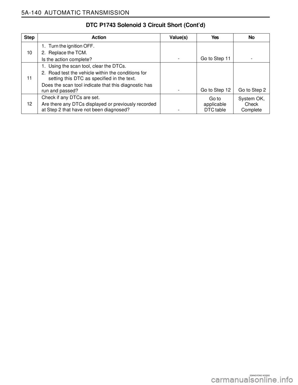
DTC P1743 Solenoid 3 Circuit Short (Cont’d)
1. Turn the ignition OFF.
2. Replace the TCM.
Is the action complete?
1. Using the scan tool, clear the DTCs.
2. Road test the vehicle within the conditions for
setting this DTC as specified in the text.
Does the scan tool indicate that this diagnostic has
run and passed?
Check if any DTCs are set.
Are there any DTCs displayed or previously recorded
at Step 2 that have not been diagnosed?
StepAction Value(s) Yes No
10
- Go to Step 11 -
- Go to Step 12 Go to Step 2 11
12
-Go to
applicable
DTC tableSystem OK,
Check
Complete
Page 1238 of 2053
AUTOMATIC TRANSMISSION 5A-143
SSANGYONG MY2002
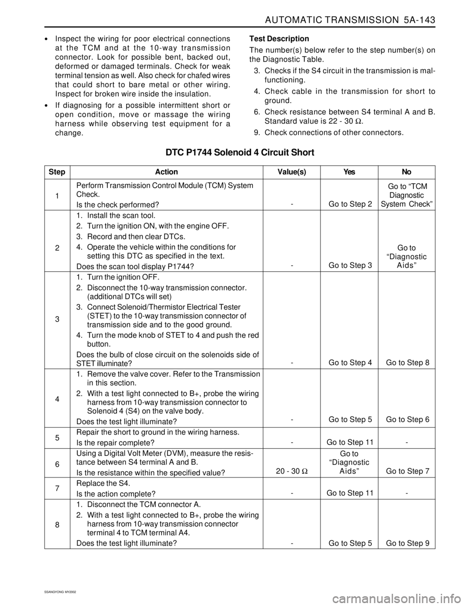
DTC P1744 Solenoid 4 Circuit Short
Inspect the wiring for poor electrical connections
at the TCM and at the 10-way transmission
connector. Look for possible bent, backed out,
deformed or damaged terminals. Check for weak
terminal tension as well. Also check for chafed wires
that could short to bare metal or other wiring.
Inspect for broken wire inside the insulation.
If diagnosing for a possible intermittent short or
open condition, move or massage the wiring
harness while observing test equipment for a
change.Test Description
The number(s) below refer to the step number(s) on
the Diagnostic Table.
3. Checks if the S4 circuit in the transmission is mal-
functioning.
4. Check cable in the transmission for short to
ground.
6. Check resistance between S4 terminal A and B.
Standard value is 22 - 30 Ω.
9. Check connections of other connectors.
- Go to Step 11 - 1Perform Transmission Control Module (TCM) System
Check.
Is the check performed?
1. Install the scan tool.
2. Turn the ignition ON, with the engine OFF.
3. Record and then clear DTCs.
4. Operate the vehicle within the conditions for
setting this DTC as specified in the text.
Does the scan tool display P1744?
1. Turn the ignition OFF.
2. Disconnect the 10-way transmission connector.
(additional DTCs will set)
3. Connect Solenoid/Thermistor Electrical Tester
(STET) to the 10-way transmission connector of
transmission side and to the good ground.
4. Turn the mode knob of STET to 4 and push the red
button.
Does the bulb of close circuit on the solenoids side of
STET illuminate?
1. Remove the valve cover. Refer to the Transmission
in this section.
2. With a test light connected to B+, probe the wiring
harness from 10-way transmission connector to
Solenoid 4 (S4) on the valve body.
Does the test light illuminate?
Repair the short to ground in the wiring harness.
Is the repair complete?
Using a Digital Volt Meter (DVM), measure the resis-
tance between S4 terminal A and B.
Is the resistance within the specified value?
Replace the S4.
Is the action complete?
1. Disconnect the TCM connector A.
2. With a test light connected to B+, probe the wiring
harness from 10-way transmission connector
terminal 4 to TCM terminal A4.
Does the test light illuminate?
StepAction Value(s) Yes No
2
3
-
Go to Step 2 Go to “TCM
Diagnostic
System Check”
- Go to Step 4 Go to Step 8
5
6 4
- Go to Step 5 Go to Step 6
- Go to Step 11 -
7
8
- Go to Step 5 Go to Step 9
- Go to Step 3Go to
“Diagnostic
Aids”
20 - 30 ΩGo to
“Diagnostic
Aids” Go to Step 7
Page 1239 of 2053
5A-144 AUTOMATIC TRANSMISSION
SSANGYONG MY2002
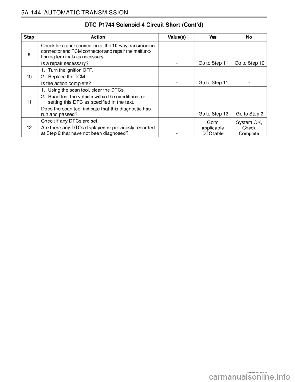
DTC P1744 Solenoid 4 Circuit Short (Cont’d)
Check for a poor connection at the 10-way transmission
connector and TCM connector and repair the malfunc-
tioning terminals as necessary.
Is a repair necessary?
1. Turn the ignition OFF.
2. Replace the TCM.
Is the action complete?
1. Using the scan tool, clear the DTCs.
2. Road test the vehicle within the conditions for
setting this DTC as specified in the text.
Does the scan tool indicate that this diagnostic has
run and passed?
Check if any DTCs are set.
Are there any DTCs displayed or previously recorded
at Step 2 that have not been diagnosed?
StepAction Value(s) Yes No
10
- Go to Step 11 -
- Go to Step 12 Go to Step 2 11
12
-Go to
applicable
DTC tableSystem OK,
Check
Complete
- Go to Step 11 Go to Step 10 9
Page 1242 of 2053
AUTOMATIC TRANSMISSION 5A-147
SSANGYONG MY2002
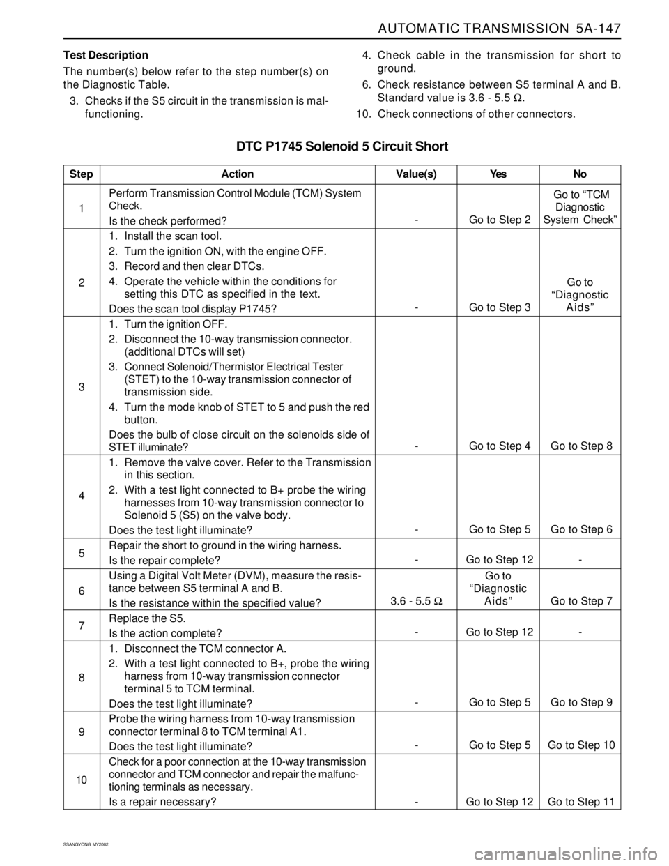
DTC P1745 Solenoid 5 Circuit Short
Test Description
The number(s) below refer to the step number(s) on
the Diagnostic Table.
3. Checks if the S5 circuit in the transmission is mal-
functioning.4. Check cable in the transmission for short to
ground.
6. Check resistance between S5 terminal A and B.
Standard value is 3.6 - 5.5 Ω.
10. Check connections of other connectors.
- Go to Step 12 - 1Perform Transmission Control Module (TCM) System
Check.
Is the check performed?
1. Install the scan tool.
2. Turn the ignition ON, with the engine OFF.
3. Record and then clear DTCs.
4. Operate the vehicle within the conditions for
setting this DTC as specified in the text.
Does the scan tool display P1745?
1. Turn the ignition OFF.
2. Disconnect the 10-way transmission connector.
(additional DTCs will set)
3. Connect Solenoid/Thermistor Electrical Tester
(STET) to the 10-way transmission connector of
transmission side.
4. Turn the mode knob of STET to 5 and push the red
button.
Does the bulb of close circuit on the solenoids side of
STET illuminate?
1. Remove the valve cover. Refer to the Transmission
in this section.
2. With a test light connected to B+ probe the wiring
harnesses from 10-way transmission connector to
Solenoid 5 (S5) on the valve body.
Does the test light illuminate?
Repair the short to ground in the wiring harness.
Is the repair complete?
Using a Digital Volt Meter (DVM), measure the resis-
tance between S5 terminal A and B.
Is the resistance within the specified value?
Replace the S5.
Is the action complete?
1. Disconnect the TCM connector A.
2. With a test light connected to B+, probe the wiring
harness from 10-way transmission connector
terminal 5 to TCM terminal.
Does the test light illuminate?
Probe the wiring harness from 10-way transmission
connector terminal 8 to TCM terminal A1.
Does the test light illuminate?
Check for a poor connection at the 10-way transmission
connector and TCM connector and repair the malfunc-
tioning terminals as necessary.
Is a repair necessary?
StepAction Value(s) Yes No
2
3
-
Go to Step 2 Go to “TCM
Diagnostic
System Check”
- Go to Step 4 Go to Step 8
5
6 4
- Go to Step 5 Go to Step 6
- Go to Step 12 -
7
8
9
- Go to Step 5 Go to Step 9
10
- Go to Step 5 Go to Step 10
- Go to Step 12 Go to Step 11
- Go to Step 3Go to
“Diagnostic
Aids”
3.6 - 5.5 ΩGo to
“Diagnostic
Aids” Go to Step 7
Page 1243 of 2053
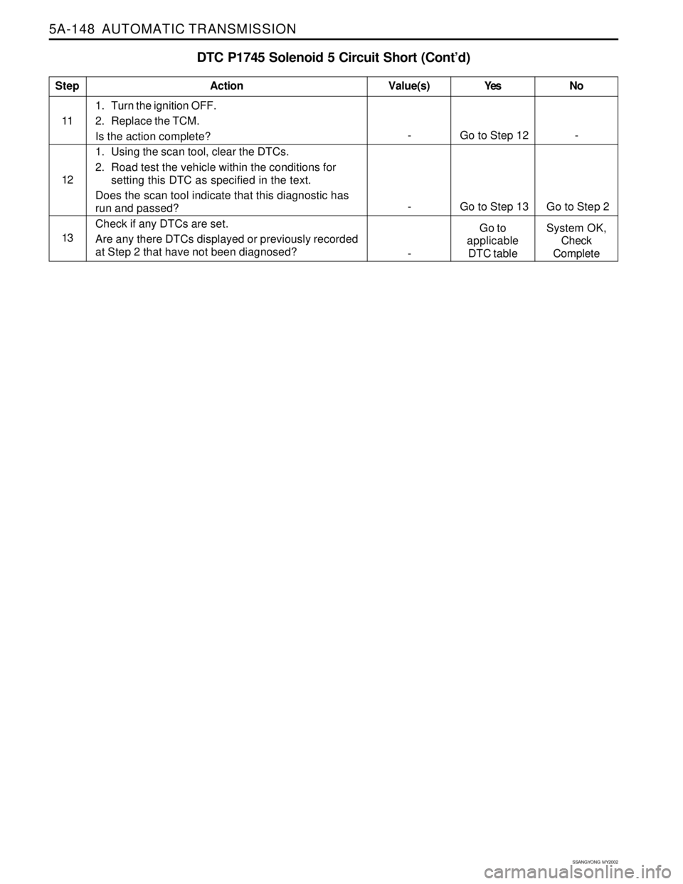
5A-148 AUTOMATIC TRANSMISSION
SSANGYONG MY2002
DTC P1745 Solenoid 5 Circuit Short (Cont’d)
1. Turn the ignition OFF.
2. Replace the TCM.
Is the action complete?
1. Using the scan tool, clear the DTCs.
2. Road test the vehicle within the conditions for
setting this DTC as specified in the text.
Does the scan tool indicate that this diagnostic has
run and passed?
Check if any DTCs are set.
Are any there DTCs displayed or previously recorded
at Step 2 that have not been diagnosed?
StepAction Value(s) Yes No
12
- Go to Step 13 Go to Step 2
13
-Go to
applicable
DTC tableSystem OK,
Check
Complete
- Go to Step 12 - 11
Page 1249 of 2053
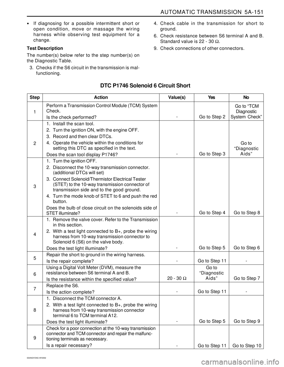
AUTOMATIC TRANSMISSION 5A-151
SSANGYONG MY2002
DTC P1746 Solenoid 6 Circuit Short
If diagnosing for a possible intermittent short or
open condition, move or massage the wiring
harness while observing test equipment for a
change.
Test Description
The number(s) below refer to the step number(s) on
the Diagnostic Table.
3. Checks if the S6 circuit in the transmission is mal-
functioning.4. Check cable in the transmission for short to
ground.
6. Check resistance between S6 terminal A and B.
Standard value is 22 - 30 Ω.
9. Check connections of other connectors.
- Go to Step 11 - 1Perform a Transmission Control Module (TCM) System
Check.
Is the check performed?
1. Install the scan tool.
2. Turn the ignition ON, with the engine OFF.
3. Record and then clear DTCs.
4. Operate the vehicle within the conditions for
setting this DTC as specified in the text.
Does the scan tool display P1746?
1. Turn the ignition OFF.
2. Disconnect the 10-way transmission connector.
(additional DTCs will set)
3. Connect Solenoid/Thermistor Electrical Tester
(STET) to the 10-way transmission connector of
transmission side and to the good ground.
4. Turn the mode knob of STET to 6 and push the red
button.
Does the bulb of close circuit on the solenoids side of
STET illuminate?
1. Remove the valve cover. Refer to the Transmission
in this section.
2. With a test light connected to B+, probe the wiring
harness from 10-way transmission connector to
Solenoid 6 (S6) on the valve body.
Does the test light illuminate?
Repair the short to ground in the wiring harness.
Is the repair complete?
Using a Digital Volt Meter (DVM), measure the
resistance between S6 terminal A and B.
Is the resistance within the specified value?
Replace the S6.
Is the action complete?
1. Disconnect the TCM connector A.
2. With a test light connected to B+, probe the wiring
harness from 10-way transmission connector
terminal 6 to TCM terminal A12.
Does the test light illuminate?
Check for a poor connection at the 10-way transmission
connector and TCM connector and repair the malfunc-
tioning terminals as necessary.
Is a repair necessary?
StepAction Value(s) Yes No
2
3
-
Go to Step 2 Go to “TCM
Diagnostic
System Check”
- Go to Step 4 Go to Step 8
5
6 4
- Go to Step 5 Go to Step 6
- Go to Step 11 -
7
8
9
- Go to Step 5 Go to Step 9
- Go to Step 11 Go to Step 10
- Go to Step 3Go to
“Diagnostic
Aids”
20 - 30 ΩGo to
“Diagnostic
Aids” Go to Step 7
Page 1250 of 2053
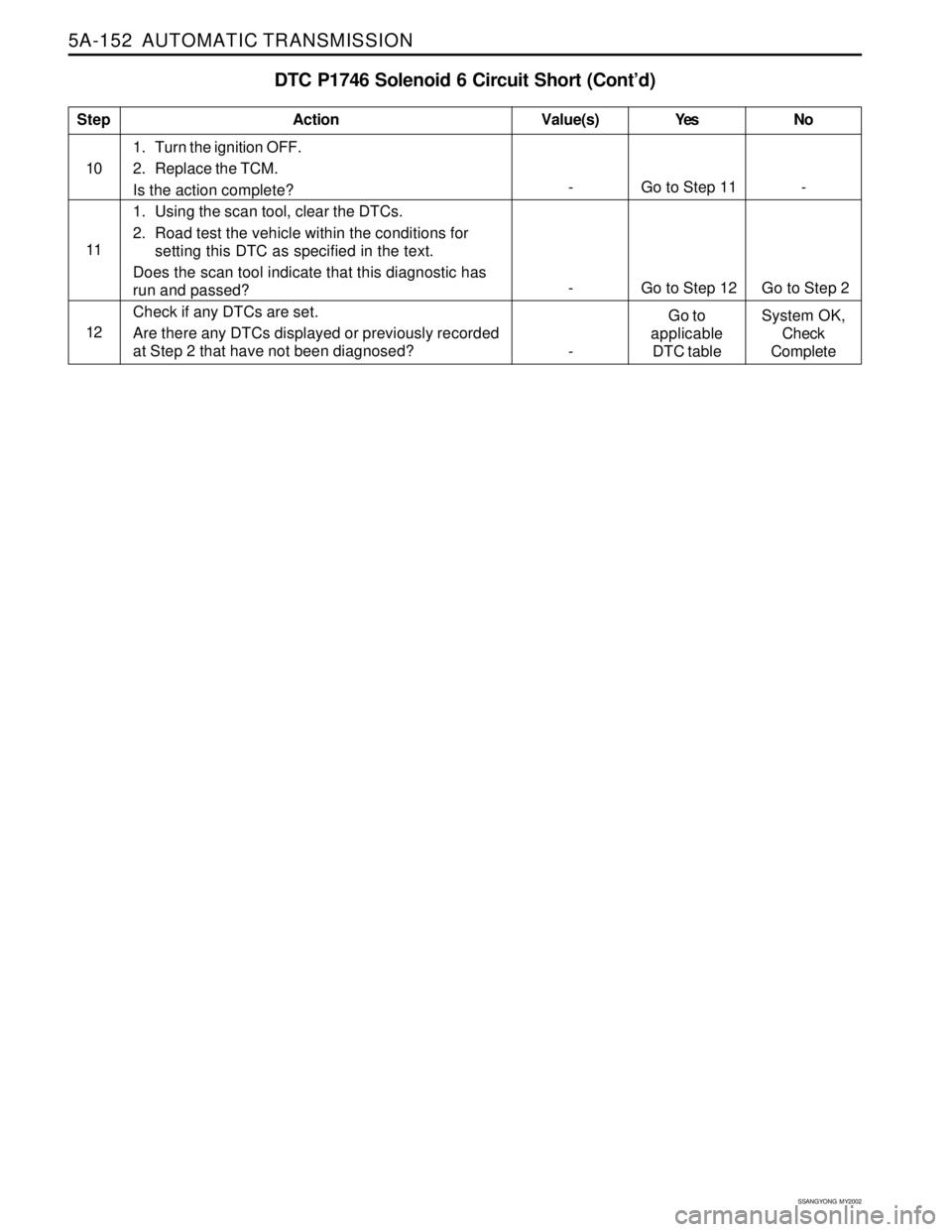
5A-152 AUTOMATIC TRANSMISSION
SSANGYONG MY2002
DTC P1746 Solenoid 6 Circuit Short (Cont’d)
1. Turn the ignition OFF.
2. Replace the TCM.
Is the action complete?
1. Using the scan tool, clear the DTCs.
2. Road test the vehicle within the conditions for
setting this DTC as specified in the text.
Does the scan tool indicate that this diagnostic has
run and passed?
Check if any DTCs are set.
Are there any DTCs displayed or previously recorded
at Step 2 that have not been diagnosed?
StepAction Value(s) Yes No
10
- Go to Step 11 -
- Go to Step 12 Go to Step 2 11
12
-Go to
applicable
DTC tableSystem OK,
Check
Complete
Page 1253 of 2053
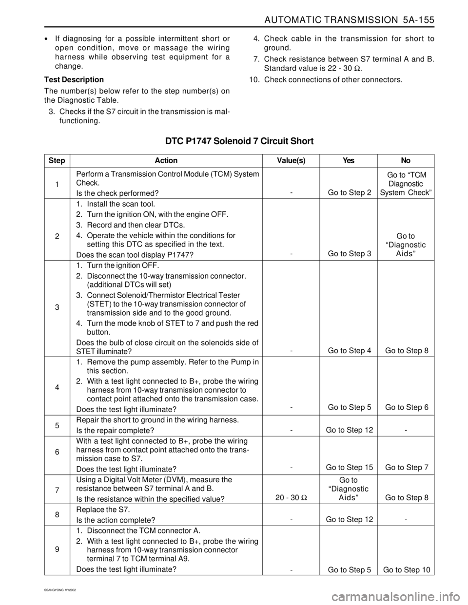
AUTOMATIC TRANSMISSION 5A-155
SSANGYONG MY2002
DTC P1747 Solenoid 7 Circuit Short
If diagnosing for a possible intermittent short or
open condition, move or massage the wiring
harness while observing test equipment for a
change.
Test Description
The number(s) below refer to the step number(s) on
the Diagnostic Table.
3. Checks if the S7 circuit in the transmission is mal-
functioning.4. Check cable in the transmission for short to
ground.
7. Check resistance between S7 terminal A and B.
Standard value is 22 - 30 Ω.
10. Check connections of other connectors.
- Go to Step 15 Go to Step 7 1Perform a Transmission Control Module (TCM) System
Check.
Is the check performed?
1. Install the scan tool.
2. Turn the ignition ON, with the engine OFF.
3. Record and then clear DTCs.
4. Operate the vehicle within the conditions for
setting this DTC as specified in the text.
Does the scan tool display P1747?
1. Turn the ignition OFF.
2. Disconnect the 10-way transmission connector.
(additional DTCs will set)
3. Connect Solenoid/Thermistor Electrical Tester
(STET) to the 10-way transmission connector of
transmission side and to the good ground.
4. Turn the mode knob of STET to 7 and push the red
button.
Does the bulb of close circuit on the solenoids side of
STET illuminate?
1. Remove the pump assembly. Refer to the Pump in
this section.
2. With a test light connected to B+, probe the wiring
harness from 10-way transmission connector to
contact point attached onto the transmission case.
Does the test light illuminate?
Repair the short to ground in the wiring harness.
Is the repair complete?
With a test light connected to B+, probe the wiring
harness from contact point attached onto the trans-
mission case to S7.
Does the test light illuminate?
Using a Digital Volt Meter (DVM), measure the
resistance between S7 terminal A and B.
Is the resistance within the specified value?
Replace the S7.
Is the action complete?
1. Disconnect the TCM connector A.
2. With a test light connected to B+, probe the wiring
harness from 10-way transmission connector
terminal 7 to TCM terminal A9.
Does the test light illuminate?
StepAction Value(s) Yes No
2
3
-
Go to Step 2 Go to “TCM
Diagnostic
System Check”
- Go to Step 4 Go to Step 8
5
6 4
- Go to Step 5 Go to Step 6
- Go to Step 12 -
7
8
9
- Go to Step 12 -
- Go to Step 5 Go to Step 10
- Go to Step 3Go to
“Diagnostic
Aids”
20 - 30 ΩGo to
“Diagnostic
Aids”
Go to Step 8