Page 1949 of 4133
Fig. 401: Identifying Permanently Installed D-Network Car Phone Components
Removal
1Disconnect ground cable of
battery
AR54.10-P-0003A
2Remove radio
3Remove stowage compartment
below radio No longer required.
4Remove cover from radio
Remove cover from radio.
5Remove AAC pushbutton
control module
6Tie out D-network antenna
lead Tied back in radio
shaft
Installation
7Modify wiring harness and
install AZ82.70-P-0001-
04GHH
8Installing hands-free system
microphoneVehicles up to 31.12.00.AZ82.70-P-0001-02E
Vehicles as of 1.1.01.AZ82.70-P-0001-02GH
9Mount holder on telephone
console and install Retrofit telephone
consoleAZ82.70-P-0001-
01GGH
2001 Mercedes-Benz ML320
1998-2005 ACCESSORIES & BODY, CAB Electrical System - Body - 163 Chassis
me
Saturday, October 02, 2010 3:30:14 PMPage 454 © 2006 Mitchell Repair Information Company, LLC.
Page 1952 of 4133
Fig. 403: Identifying Connector, Connection Line & Interface
5. Apply special glue to rear of microphone (arrow) and glue hands-free system microphone (B25) included
in installation kit to headliner.
Align microphone so that pickup opening points towards driver.
Fig. 404: Locating Rear Of Microphone & Hands
-Free System Microphone (B25)
6. Glue microphone lead behind headliner as shown in figure and along right A-pillar below instrument
panel to radio shaft.
7. Connect all control and operation modules and connect battery for checking proper function of telephone.
Avoid error messa
ges from unconnected control modules.
2001 Mercedes-Benz ML320
1998-2005 ACCESSORIES & BODY, CAB Electrical System - Body - 163 Chassis
me
Saturday, October 02, 2010 3:30:14 PMPage 457 © 2006 Mitchell Repair Information Company, LLC.
Page 1955 of 4133
gas. Risk of poisoning
and caustic burns from
swallowing battery
electrolyte. Risk of
injury from caustic burns
to eyes and skin from
battery electrolyte or
from handling damaged
lead-acid batteriesflames or smoking. Wear
acid-resistant gloves,
clothing and glasses. Pour
battery electrolyte only
into suitable and
appropriately marked
containers.
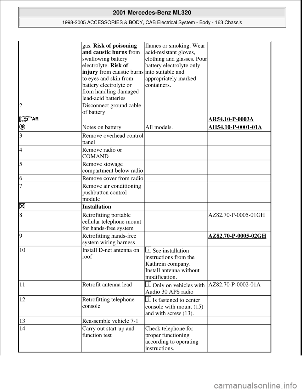
2Disconnect ground cable
of battery
AR54.10-P-0003A
Notes on batteryAll models.AH54.10-P-0001-01A
3Remove overhead control
panel
4Remove radio or
COMAND
5Remove stowage
compartment below radio
6Remove cover from radio
7Remove air conditioning
pushbutton control
module
Installation
8Retrofitting portable
cellular telephone mount
for hands-free system AZ82.70-P-0005-01GH
9Retrofitting hands-free
system wiring harness AZ82.70-P-0005-02GH
10Install D-net antenna on
roof See installation
instructions from the
Kathrein company.
Install antenna without
modification.
11Retrofit antenna lead Only on vehicles with
Audio 30 APS radioAZ82.70-P-0002-01A
12Retrofitting telephone
console Is fastened to center
console with mount (15)
and with screw (13).
13Reassemble vehicle 7-1
14Carry out start-up and
function testCheck telephone for
proper functioning
according to operating
instructions.
2001 Mercedes-Benz ML320
1998-2005 ACCESSORIES & BODY, CAB Electrical System - Body - 163 Chassis
me
Saturday, October 02, 2010 3:30:14 PMPage 460 © 2006 Mitchell Repair Information Company, LLC.
Page 1957 of 4133
Fig. 409: Identifying Portable CTEL Components
Removal
1Disconnect ground cable
of battery
AR54.10-P-0003A
2Remove radio or
COMAND
3Remove stowage
compartment below radio
4Remove cover from radio
5Remove air conditioning
pushbutton control
module
6Remove overhead control
panel
7Tie antenna lead Tied back in radio
shaft
Install
8Covering fiber optic
cable Do not kink or
stretch D2B fiber optic
cable.
Install caps on fiber
optic cable connector and
2001 Mercedes-Benz ML320
1998-2005 ACCESSORIES & BODY, CAB Electrical System - Body - 163 Chassis
me
Saturday, October 02, 2010 3:30:14 PMPage 462 © 2006 Mitchell Repair Information Company, LLC.
Page 1965 of 4133
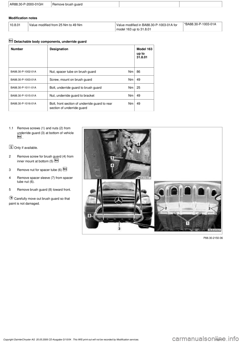
AR88.30-P-2000-01GH
Remove brush guard
Modification notes
10.8.01
Value modified from 25 Nm to 49 Nm
Value modified in BA88.30-P-1003-01A for
model 163 up to 31.8.01
*BA88.30-P-1003-01A
Detachable body components, underride guard
Number
Designation
Model 163
up to
31.8.01
BA88.30-P-1002-01A
Nut, spacer tube on brush guard
Nm
86
BA88.30-P-1003-01A
Screw, mount on brush guard
Nm
49
BA88.30-P-1011-01A
Bolt, underride guard to brush guard
Nm
25
BA88.30-P-1015-01A
Nut, underride guard to bracket
Nm
49
BA88.30-P-1016-01A
Bolt, front section of underride guard to rear
section of underride guard
Nm
49
P88.30-2150-06
1.1
Remove screws (1) and nuts (2) from
underride guard (3) at bottom of vehicle
.
Only if available.
2
Remove screw for brush guard (4) from
inner mount at bottom (5)
3
Remove nut for spacer tube (6)
4
Remove spacer sleeve (7) from spacer
tube nut (6).
5
Remove brush guard (8) toward front.
Carefully move out brush guard so that
paint is not damaged.
Copyright DaimlerChrysler AG 20.05.2006 CD-Ausgabe G/10/04 . This WIS print-out will not be recorde
d by Modification services.
Page 1
Page 1972 of 4133
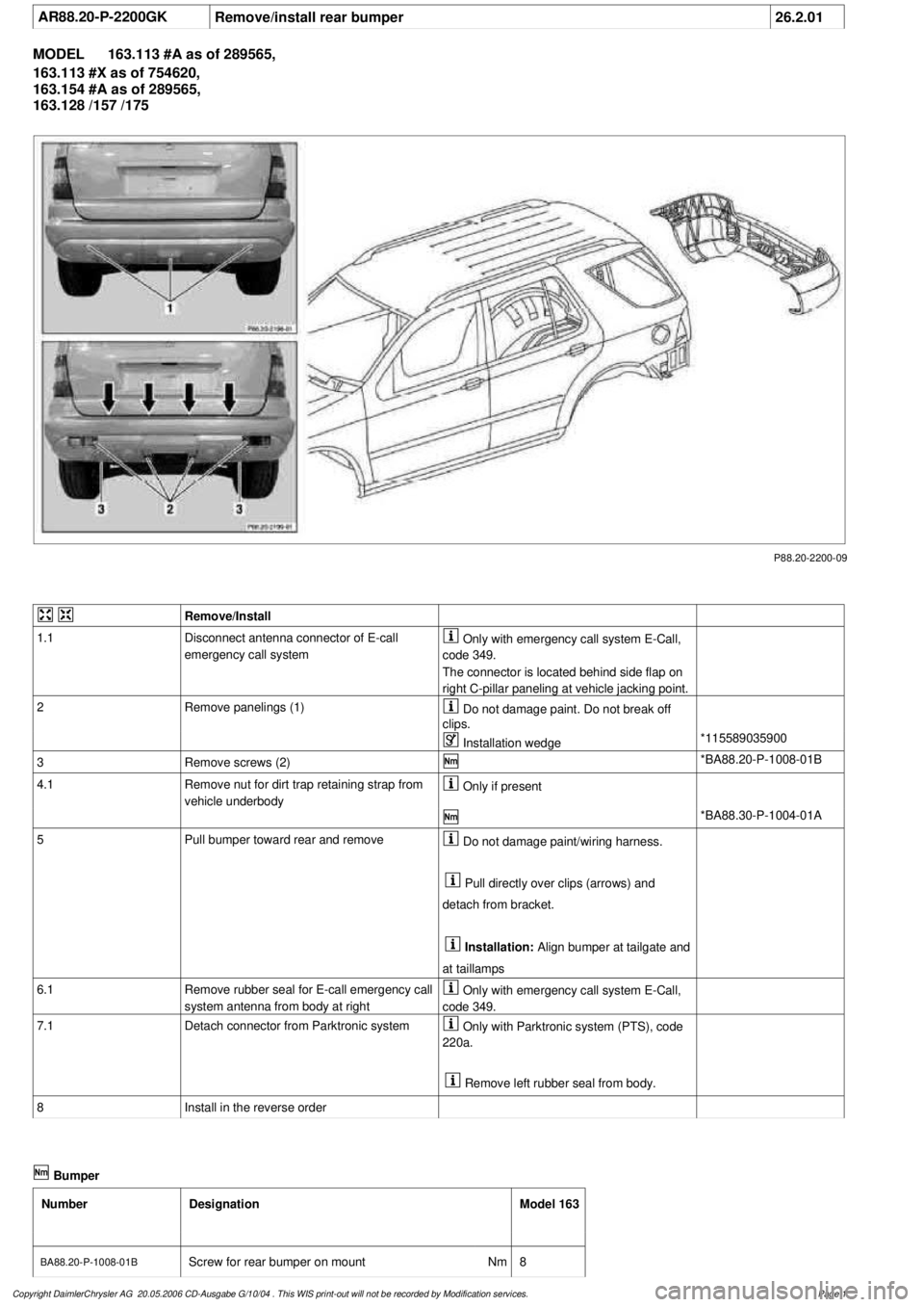
AR88.20-P-2200GK
Remove/install rear bumper
26.2.01
MODEL
163.113 #A as of 289565,
163.113 #X as of 754620,
163.154 #A as of 289565,
163.128 /157 /175
P88.20-2200-09
Remove/Install
1.1
Disconnect antenna connector of E-call
emergency call system
Only with emergency call system E-Call,
code 349.
The connector is located behind side flap on
right C-pillar paneling at vehicle jacking point.
2
Remove panelings (1)
Do not damage paint. Do not break off
clips.
Installation wedge
*115589035900
3
Remove screws (2)
*BA88.20-P-1008-01B
4.1
Remove nut for dirt trap retaining strap from
vehicle underbody
Only if present
*BA88.30-P-1004-01A
5
Pull bumper toward rear and remove
Do not damage paint/wiring harness.
Pull directly over clips (arrows) and
detach from bracket.
Installation:
Align bumper at tailgate and
at taillamps
6.1
Remove rubber seal for E-call emergency call
system antenna from body at right
Only with emergency call system E-Call,
code 349.
7.1
Detach connector from Parktronic system
Only with Parktronic system (PTS), code
220a.
Remove left rubber seal from body.
8
Install in the reverse order
Bumper
Number
Designation
Model 163
BA88.20-P-1008-01B
Screw for rear bumper on mount
Nm
8
Copyright DaimlerChrysler AG 20.05.2006 CD-Ausgabe G/10/04 . This WIS print-out will not be recorde
d by Modification services.
Page 1
Page 1979 of 4133
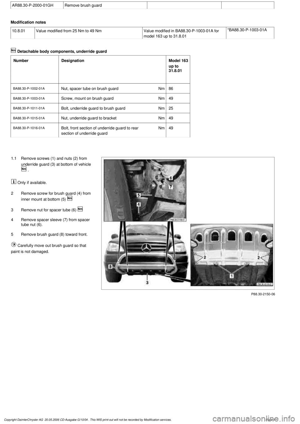
AR88.30-P-2000-01GH
Remove brush guard
Modification notes
10.8.01
Value modified from 25 Nm to 49 Nm
Value modified in BA88.30-P-1003-01A for
model 163 up to 31.8.01
*BA88.30-P-1003-01A
Detachable body components, underride guard
Number
Designation
Model 163
up to
31.8.01
BA88.30-P-1002-01A
Nut, spacer tube on brush guard
Nm
86
BA88.30-P-1003-01A
Screw, mount on brush guard
Nm
49
BA88.30-P-1011-01A
Bolt, underride guard to brush guard
Nm
25
BA88.30-P-1015-01A
Nut, underride guard to bracket
Nm
49
BA88.30-P-1016-01A
Bolt, front section of underride guard to rear
section of underride guard
Nm
49
P88.30-2150-06
1.1
Remove screws (1) and nuts (2) from
underride guard (3) at bottom of vehicle
.
Only if available.
2
Remove screw for brush guard (4) from
inner mount at bottom (5)
3
Remove nut for spacer tube (6)
4
Remove spacer sleeve (7) from spacer
tube nut (6).
5
Remove brush guard (8) toward front.
Carefully move out brush guard so that
paint is not damaged.
Copyright DaimlerChrysler AG 20.05.2006 CD-Ausgabe G/10/04 . This WIS print-out will not be recorde
d by Modification services.
Page 1
Page 1980 of 4133
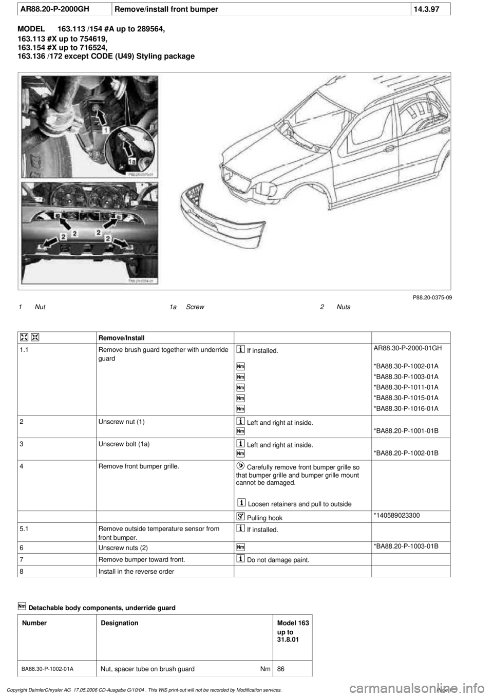
AR88.20-P-2000GH
Remove/install front bumper
14.3.97
MODEL
163.113 /154 #A up to 289564,
163.113 #X up to 754619,
163.154 #X up to 716524,
163.136 /172 except CODE (U49) Styling package
P88.20-0375-09
1
Nut
2
Nuts
1a
Screw
Remove/Install
1.1
Remove brush guard together with underride
guard
If installed.
AR88.30-P-2000-01GH
*BA88.30-P-1002-01A
*BA88.30-P-1003-01A
*BA88.30-P-1011-01A
*BA88.30-P-1015-01A
*BA88.30-P-1016-01A
2
Unscrew nut (1)
Left and right at inside.
*BA88.20-P-1001-01B
3
Unscrew bolt (1a)
Left and right at inside.
*BA88.20-P-1002-01B
4
Remove front bumper grille.
Carefully remove front bumper grille so
that bumper grille and bumper grille mount
cannot be damaged.
Loosen retainers and pull to outside
Pulling hook
*140589023300
5.1
Remove outside temperature sensor from
front bumper.
If installed.
6
Unscrew nuts (2)
*BA88.20-P-1003-01B
7
Remove bumper toward front.
Do not damage paint.
8
Install in the reverse order
Detachable body components, underride guard
Number
Designation
Model 163
up to
31.8.01
BA88.30-P-1002-01A
Nut, spacer tube on brush guard
Nm
86
Copyright DaimlerChrysler AG 17.05.2006 CD-Ausgabe G/10/04 . This WIS print-out will not be recorde
d by Modification services.
Page 1