1997 MERCEDES-BENZ ML500 tow
[x] Cancel search: towPage 1398 of 4133
Shifting 2nd gear with program selection "W" or "C" (depending on the production period).
Function
Start engine -
The working pressure (p-A) is formed, reaches via the holding pressure 2-3 shift valve, the command valve 2-3
and ball valve (33a) to the rear multi-disc clutch (K3) and via the command valve 3-4 (31c) to the end face of
the shift pressure 3-4 (29c) shift valve. The 3-4 shift pressure shift valve (29c) is moved against the force of the
spring towards the right. At the same time the 3-4 solenoid valve (Y3/6y4) is energized.
The ECT control unit (N15/3) monitors the engagement process via the reduced speed of the drive shaft as the
frictional connection of the rear multi-disc brake increases. When the speed drops to the specified level, the
ECT control module (N15/3) shuts off the power to the 3-4 shift solenoid valve (Y3/6y4). The spring chamber
of the shift valve B2 (26) is depressurized and switches downward. As a result the line to the opposed surface of
the rear multi-disc brake piston (B2b) is connected to the pressure maintaining valve (32). The pressure on the
opposed surface of the rear multi-disc brake piston (B2b) reduces to a residual pressure.
The 3-4 command valve (31c) moves to the left. The working pressure (p-A) reaches via the holding pressure
shift valve 3-4 (28c) and the command valve 3-4 (31c) to the piston of the rear multi-disc brake (B2a).
The activation sequence is complete; 1st gear is engaged (See Fig. 130
.
As a result shift valve pressure (p-SV) reaches the spring chamber of the shift valve B2 (26) and the end face of
the command valve 3-4 (31c).
The shift valve B2 (26) is held in the upper position and the 3-4 command valve (31c) switches towards the
right.
The working pressure (p-a) is replaced by the shift valve pressure (p-SV) at the end face of the shift pressure 3-
4 shift valve (See Fig. 131
).
Move Selector Lever From "N" To "D"
The selector lever (52) opens the shift pressure (p-S) feed connection from the ball valve (33b) with the shift
valve B2 (26). In the upper position of the shift valve B2 (26) shift pressure (p-S) reaches behind (p-S) the
piston of the multi-disc brake (B2a) and simultaneously to the opposed surface of the rear multi-disc brake
piston (B2b).
The rear multi-disc brake begins to close. See Fig. 132
.
The pressure on the opposed surface of the piston of the rear multi-disc brake (B2b) causes a gentle engagement
of the rear multi-disc brake.
Move Selector Lever From "N" To "R"
The selector valve (52) opens the connection of the feed of shift pressure (p-S) with the center multi-disc brake
2001 Mercedes-Benz ML320
1998-03 AUTOMATIC TRANSMISSIONS Complete Transmissions - ML 320 - 722.662
me
Saturday, October 02, 2010 3:15:28 PMPage 229 © 2006 Mitchell Repair Information Company, LLC.
Page 1457 of 4133
When the kick-down switch (S16/6) is operated via the accelerator pedal a signal is passed on to the ETC
control module (N15/3). Based on this information the ETC control module (N15/3) actuates the solenoid
valves so that the upshifts and downshifts take place at higher engine speed.
Shift-Lock Function
Operation
The term shift lock combines the functions which, in addition to the parking brake, offer an additional safeguard
for the vehicle to prevent it moving off unintentionally.
These include the functions of locking the selector lever position "P" and locking the ignition lock as well as the
parking lock in the transmission.
The shift lock function only allows shifting out of selector lever position "P" if the transmitter key (A8/1) has
been turned into the position "Ignition: ON" and the brake pedal is depressed.
In order to ensure that after parking the vehicle the selector lever is shifted into selector lever position "P", the
transmitter key (A8/1) can only be turned towards "0" in this position and removed from the EZS control
module (N73) (ignition lock locking, function).
The vehicle is secured mechanically by blocking the park pawl gear.
In the event of mechanical or electrical/electronic faults it is possible to unlock selector lever position "P"
manually (shift lock override function).
Function Of Locking Of Selector Lever Position "P"
See FUNCTION OF LOCKING OF SELECTOR LEVER POSITION "P"
.
Ignition Lock Locking, Function
See IGNITION LOCK INTERLOCK
.
Function Of Shift Lock Override
See FUNCTION OF SHIFT LOCK OVERRIDE
.
Function Of Locking Of Selector Lever Position "P" (With Touch Shift)
Operation
2001 Mercedes-Benz ML320
1998-03 AUTOMATIC TRANSMISSIONS Complete Transmissions - ML 320 - 722.662
me
Saturday, October 02, 2010 3:15:30 PMPage 288 © 2006 Mitchell Repair Information Company, LLC.
Page 1491 of 4133
AR91.12-P-1100GH
Remove and install cover on bottom of rear seat
22.2.00
MODELS
163.136 /154 /172 as of 1.9.99,
163.113 /128 /157 /174 /175
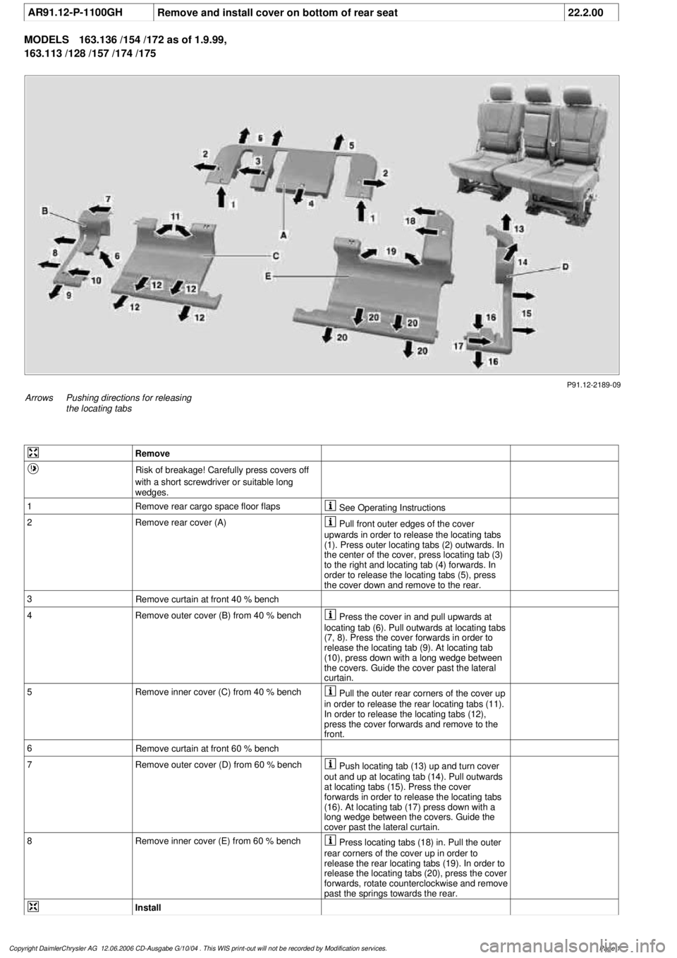
P91.12-2189-09
Arrows
Pushing directions for releasing
the locating tabs
Remove
Risk of breakage! Carefully press covers off
with a short screwdriver or suitable long
wedges.
1
Remove rear cargo space floor flaps
See Operating Instructions
2Remove rear cover (A)
Pull front outer edges of the cover
upwards in order to release the locating tabs
(1). Press outer locating tabs (2) outwards. In
the center of the cover, press locating tab (3)
to the right and locating tab (4) forwards. In
order to release the locating tabs (5), press
the cover down and remove to the rear.
3
Remove curtain at front 40 % bench
4
Remove outer cover (B) from 40 % bench
Press the cover in and pull upwards at
locating tab (6). Pull outwards at locating tabs
(7, 8). Press the cover forwards in order to
release the locating tab (9). At locating tab
(10), press down with a long wedge between
the covers. Guide the cover past the lateral
curtain.
5
Remove inner cover (C) from 40 % bench
Pull the outer rear corners of the cover up
in order to release the rear locating tabs (11).
In order to release the locating tabs (12),
press the cover forwards and remove to the
front.
6
Remove curtain at front 60 % bench
7
Remove outer cover (D) from 60 % bench
Push locating tab (13) up and turn cover
out and up at locating tab (14). Pull outwards
at locating tabs (15). Press the cover
forwards in order to release the locating tabs
(16). At locating tab (17) press down with a
long wedge between the covers. Guide the
cover past the lateral curtain.
8
Remove inner cover (E) from 60 % bench
Press locating tabs (18) in. Pull the outer
rear corners of the cover up in order to
release the rear locating tabs (19). In order to
release the locating tabs (20), press the cover
forwards, rotate counterclockwise and remove
past the springs towards the rear.
Install
Copyright DaimlerChrysler AG 12.06.2006 CD-Ausgabe G/10/04 . This WIS print-out will not be recorde
d by Modification services.
Page 1
Page 1549 of 4133
REAR WASH - FUNCTION - GF82.35-P-3001GH
MODEL 163
The rear wash function is activated by placing the rear wiper/ washer switch (S78) in the down position. The
switch contact connects the tailgate washer pump (M5/3) to terminal 15. The All Activity Module (AAM)
(N10) detects the activation of the switch via the second switch contact and actuates the tailgate washer motor
(M6/4) and the tailgate washer fluid pump (M5/3) for as long as the switch is on.
The activation time for the tailgate washer fluid pump (M5/3)is limited to 15 sec. To reactivate the pump, the
button must be pressed again.
To wipe window dry, the tailgate wiper motor (M6/4) remains activated for five seconds after the switch is
released.
As described for the rear wiper function, a relay circuit in the wiper motor stops the wiper in the park position .
WINDSHIELD WASH - FUNCTION - GF82.35-P-3002GH
MODEL 163
The windshield wash function is activated by pulling the combination switch, washer switch (S4s4) towards
the steering column. The switch contact connects the washer pump (M5/1) to terminal 15R. The All Activity
Module (AAM) (N10) detects switch activation via an input that measures power supply to the washer pump
(M5/1).
If the combination switch (S4) is in the Wiper Off or Intermittent position, the AAM activates the wiper
motor (M6/1) via rela
y F1k17 . To wipe windshield dry, the motor continues to operate after the switch has
Rear window washer
pump, location /
purpose / design /
function GF82.35-P-4103GH
Table of contents,
function description,
wiper system (WS) GF82.30-P-0998GH
Rear Wipe GF82.30-P-3004GH
Rear Wiper/Washer
Switch GF82.30-P-4105GH
Tailgate Wiper Motor GF82.30-P-4106GH
Tailgate Washer Pump GF82.35-P-4103GH
All Activity ModuleTo 30.11.99GF54.21-P-4100GH
As of 1.12.99GF54.21-P-4100GK
2001 Mercedes-Benz ML320
1998-2005 ACCESSORIES & BODY, CAB Electrical System - Body - 163 Chassis
me
Saturday, October 02, 2010 3:30:05 PMPage 54 © 2006 Mitchell Repair Information Company, LLC.
Page 1567 of 4133
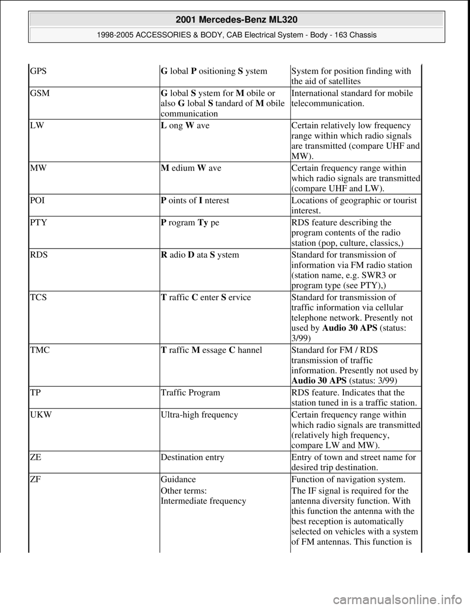
GPSG lobal P ositioning S ystemSystem for position finding with
the aid of satellites
GSMG lobal S ystem for M obile or
also G lobal S tandard of M obile
communicationInternational standard for mobile
telecommunication.
LWL ong W aveCertain relatively low frequency
range within which radio signals
are transmitted (compare UHF and
MW).
MWM edium W aveCertain frequency range within
which radio signals are transmitted
(compare UHF and LW).
POIP oints of I nterestLocations of geographic or tourist
interest.
PTYP rogram Ty peRDS feature describing the
program contents of the radio
station (pop, culture, classics,)
RDSR adio D ata S ystemStandard for transmission of
information via FM radio station
(station name, e.g. SWR3 or
program type (see PTY),)
TCST raffic C enter S erviceStandard for transmission of
traffic information via cellular
telephone network. Presently not
used by Audio 30 APS (status:
3/99)
TMCT raffic M essage C hannelStandard for FM / RDS
transmission of traffic
information. Presently not used by
Audio 30 APS (status: 3/99)
TPTraffic ProgramRDS feature. Indicates that the
station tuned in is a traffic station.
UKWUltra-high frequencyCertain frequency range within
which radio signals are transmitted
(relatively high frequency,
compare LW and MW).
ZEDestination entryEntry of town and street name for
desired trip destination.
ZFGuidanceFunction of navigation system.
Other terms:
Intermediate frequencyThe IF signal is required for the
antenna diversity function. With
this function the antenna with the
best reception is automatically
selected on vehicles with a system
of FM antennas. This function is
2001 Mercedes-Benz ML320
1998-2005 ACCESSORIES & BODY, CAB Electrical System - Body - 163 Chassis
me
Saturday, October 02, 2010 3:30:05 PMPage 72 © 2006 Mitchell Repair Information Company, LLC.
Page 1578 of 4133
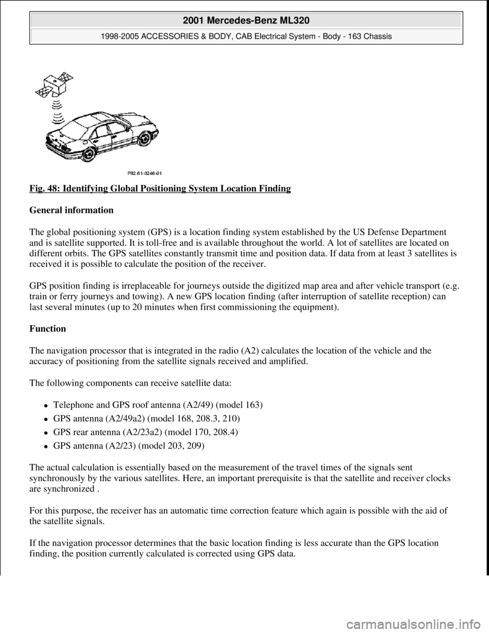
Fig. 48: Identifying Global Positioning System Location Finding
General information
The global positioning system (GPS) is a location finding system established by the US Defense Department
and is satellite supported. It is toll-free and is available throughout the world. A lot of satellites are located on
different orbits. The GPS satellites constantly transmit time and position data. If data from at least 3 satellites is
received it is possible to calculate the position of the receiver.
GPS position finding is irreplaceable for journeys outside the digitized map area and after vehicle transport (e.g.
train or ferry journeys and towing). A new GPS location finding (after interruption of satellite reception) can
last several minutes (up to 20 minutes when first commissioning the equipment).
Function
The navigation processor that is integrated in the radio (A2) calculates the location of the vehicle and the
accuracy of positioning from the satellite signals received and amplified.
The following components can receive satellite data:
Telephone and GPS roof antenna (A2/49) (model 163)
GPS antenna (A2/49a2) (model 168, 208.3, 210)
GPS rear antenna (A2/23a2) (model 170, 208.4)
GPS antenna (A2/23) (model 203, 209)
The actual calculation is essentially based on the measurement of the travel times of the signals sent
synchronously by the various satellites. Here, an important prerequisite is that the satellite and receiver clocks
are synchronized .
For this purpose, the receiver has an automatic time correction feature which again is possible with the aid of
the satellite signals.
If the navigation processor determines that the basic location finding is less accurate than the GPS location
findin
g, the position currently calculated is corrected using GPS data.
2001 Mercedes-Benz ML320
1998-2005 ACCESSORIES & BODY, CAB Electrical System - Body - 163 Chassis
me
Saturday, October 02, 2010 3:30:05 PMPage 83 © 2006 Mitchell Repair Information Company, LLC.
Page 1580 of 4133
and is available worldwide . Presently there are 266 satellites on 6 different earth orbits. The GPSsatellites
permanently transmit time and position data. If data from a minimum of 3 satellites is received (with two-
dimensional location finding) it is possible to calculate the position of the receiver.
The GPS location finding is particularly important when driving outside of the digitized map area and
following vehicle transport (e.g. train, ferry or towing).
A repeated GPS location finding (following satellite reception interruption) can take several minutes (when
unit is initially started up to 20 min .).
GPS map matching function
The navigation processor calculates the location of the vehicle and the accuracy of positioning from the
satellite signals received and amplified by the GPS antenna (A2/49) . The current calculation is based
primarily on the measurement of the transmission times for the signals transmitted synchronously by the
various satellites. Here, an important prerequisite is that the satellite and receiver clocks are synchronized . For
this purpose, the receiver has an automatic time correction feature which again is possible with the aid of the
satellite signals. If the navigation processor determines that the basic location finding is less precise than the
GPS location finding, the currently calculated position is corrected with the aid of the GPS data .
Moreover, the vehicle route is determined from the location sequence calculated with GPS .
Approx. 50 new GPS location finding calculations are performed each minute.
Possible interference when receiving GPS signals
Since GPS operates in the GHz (microwave) range and the signals are weak, reception interferences can
occur from
atmospheric interferences, e.g. weather, water vapor, fog,
multiple path reception due to signal reflections, e.g. from building walls
Signal shadows, e.g. in built-up areas, tunnels, high buildings, trees
A free view of the sky is therefore necessary for GPS reception The location finding accuracy is approx. 100
m or better .
Basic location finding,
function GF82.61-P-3006GI
Map-supported location
finding, function GF82.61-P-3008GI
Guidance, function GF82.61-P-3012GI
Radio and navigation
module, location/purpose/
design/function GF82.61-P-4109GI
GPS roof antenna/telephone, GF82.70-P-4111A
2001 Mercedes-Benz ML320
1998-2005 ACCESSORIES & BODY, CAB Electrical System - Body - 163 Chassis
me
Saturday, October 02, 2010 3:30:05 PMPage 85 © 2006 Mitchell Repair Information Company, LLC.
Page 1589 of 4133
Driving direction recommendation
Distance to next turning point (specified in units of length)
The data is determined by the navigation processor and transmitted to the radio and navigation module
(A2/56) The current route guidance is primarily supported by the voice output (English).
The scale of the displayed map can be changed in increments. In addition it is possible to select whether the
map is aligned in the direction of motion Head-Up ) or toward the north North-Up ). The graphical signals for
map illustration is generated by the navigation processor.
DESTINATION GUIDANCE IN NON-DIGITALIZED MAP AREA, FUNCTION - GF82.61-P-4001C
MODEL 163, 168, 170, 203.0 /2 /7, 208, 209.3 /4, 210 with CODE (353) Audio 30 APS
When traveling outside of the digitized map area (e.g. company grounds, parking buildings, dirt roads,...),
however still within the DVD map boundaries, the navigation processor switches over to "navigation system in
non-digitized map area".
On the radio (A2) display the following message appears:
"OFF ROAD"
If the vehicle is also outside the DVD map limit, the following message appears:
"OFF MAP"
In both cases, only basic location finding is accomplished with correction using the GPS data.
A (limited) route guidance can be conducted only with specification of the:
Distance from the destination as the crow flies
Direction to the destination (as an arrow)
After reentering the digitized map area, the system automatically continues with "navigation system in digitized
map area". The possible streets/roads on which the vehicle may be located are determined with the aid of GPS
location finding. During this process a slight delay in the route guidance may result.
The road data of several Central European countries are stored on the navigation DVD, so that the "OFF
MAP" message will not appear, if borders between the stored countries are crossed. No special foreign country
DVD has to be inserted.
Voice output, function GF82.85-P-3001GI
Guidance in non-digitized
map area, function GF82.61-P-4001GI
2001 Mercedes-Benz ML320
1998-2005 ACCESSORIES & BODY, CAB Electrical System - Body - 163 Chassis
me
Saturday, October 02, 2010 3:30:05 PMPage 94 © 2006 Mitchell Repair Information Company, LLC.