Page 1597 of 4133
DVD drive and DVD
The DVD drive of the radio (A2) reads data from the navigation DVD inserted and makes this available to the
navigation processor via the data bus inside the device.
Audio CDs can also be played.
The following are located on the navigation DVD:
Program data for the navigation computer
Voice segments for voice output
Map data.
A distinction is made between digitized and non-digitized areas within the DVD map area:
Villages, towns, roads, intersections and their attributes (e.g. one-way streets, no turns etc.) are recorded
in the digitized map area.
Included in the non-digitized areas are, for example company/private grounds, farms, small housing
estates, tracks across fields and areas between villages.
No data is available here.
Diagnosis interface (K-line) and fault management of D2B-components
During operation, the system stores all occurring faults in the nonvolatile memory. It is not possible to output
the fault via the display of the radio (A2).
The radio's (A2) fault management also includes the D2B-components connected. For this purpose, each D2B
component has its own DTC memory. The faults are transmitted from the corresponding components via the
D2B to the radio (A2) and can then be read out via the diagnosis interface
RADIO AND NAVIGATION MODULE, FUNCTION - GF82.61-P-4109-04GI
Processing button actuations
The control buttons and switches on the function keypad on the radio and navigation module (A2/56)are read
in via the I/O ports of the microcontroller and transferred to the central processor. Depending on the system
function the button actuations are processed in the central processor or relayed to the other system components
via the digital data bus ( D2B ) in form of a data telegram.
Graphic preparation and image output
The graphics subsystem handles the preparation and output of the operating displays. The operating displays are
output internally to the display by the graphic subsystem via the RGB output ( R =red, G =green, B =blue).
The RGB signal contains information and amplitudes of the three basic colors Red, G reen and Blue as well
2001 Mercedes-Benz ML320
1998-2005 ACCESSORIES & BODY, CAB Electrical System - Body - 163 Chassis
me
Saturday, October 02, 2010 3:30:05 PMPage 102 © 2006 Mitchell Repair Information Company, LLC.
Page 1599 of 4133
Map data.
The digitized map area on the CD-ROM contains towns, cities, streets, intersections and their attributes (e.g.:
one-way streets, turn prohibitions, ...). It does not contain information about company and private ground,
farms, housing estates and agricultural roads.
Gyrosensor
The gyrosensor determines the direction change of the vehicle. It is installed in the navigation processor .
Calibration is not required.
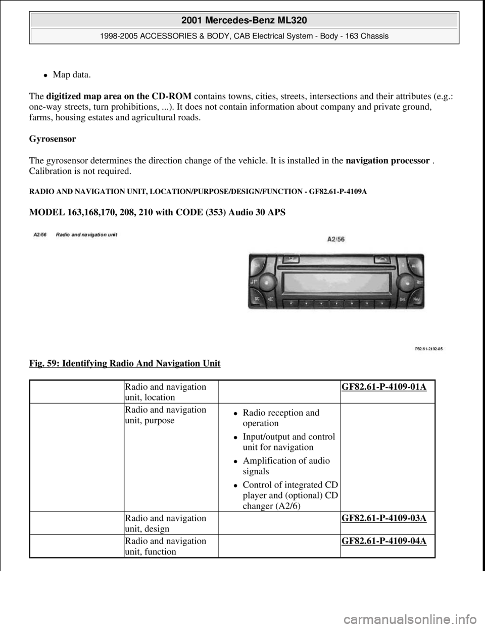
RADIO AND NAVIGATION UNIT, LOCATION/PURPOSE/DESIGN/FUNCTION - GF82.61-P-4109A
MODEL 163,168,170, 208, 210 with CODE (353) Audio 30 APS
Fig. 59: Identifying Radio And Navigation Unit
Radio and navigation
unit, location GF82.61-P-4109-01A
Radio and navigation
unit, purposeRadio reception and
operation
Input/output and control
unit for navigation
Amplification of audio
signals
Control of integrated CD
player and (optional) CD
changer (A2/6)
Radio and navigation
unit, design GF82.61-P-4109-03A
Radio and navigation
unit, function GF82.61-P-4109-04A
2001 Mercedes-Benz ML320
1998-2005 ACCESSORIES & BODY, CAB Electrical System - Body - 163 Chassis
me
Saturday, October 02, 2010 3:30:05 PMPage 104 © 2006 Mitchell Repair Information Company, LLC.
Page 1759 of 4133
INSTALLING AUXILIARY CABLE HARNESS ON SIDE WALL TAILLAMP - AR82.10-P-4920-01GH
Models 163.154/174 as of VINA289565 to VIN A371934, model 163.175 up to VIN A371934 with USA
version code 494a
1. Insert plug (1) of auxiliary cable harness (2) in socket (3) of side-marker lamp.
2. Insert the plug on the other end of the wiring harness in the free connection pins in the opening (4) of the
lamp support (5).
The brown line (ground) should be on the outside. Ensure that the plugs are completely pushed onto
the connection pins.
3. Seal the lines and opening (4) with a thermoplastic adhesive gun.
Give the adhesive sufficient time to dr
y before installing the taillamp.
distance of the cover to
the bumper is even.
5Unhook left front
headlamp unit (E1) or
right front headlamp unit
(E2) from the hole (arrow
B) using drift (4) and pull
forwards
6Disconnect headlamp
harness connector (X24)
7Remove headlamp unit
toward front
8Install in the reverse order
9Perform function check
10Check and correct
headlamp adjustment
Check and correct
headlamp adjustment AP82.10-P-8260GH
2001 Mercedes-Benz ML320
1998-2005 ACCESSORIES & BODY, CAB Electrical System - Body - 163 Chassis
me
Saturday, October 02, 2010 3:30:09 PMPage 264 © 2006 Mitchell Repair Information Company, LLC.
Page 1777 of 4133
Wiper
Fig. 185: Identifying Puller (001 589 38 33 00)
REMOVE/INSTALL RAIN SENSOR - AR82.30-P-7700GH
MODELS 163.113 /128 /154 /157 /172 /174 /175 with CODE (345a) Rain sensor
Fig. 185
4Reinstall in opposite
order When installing:
Attach wiper arms so that
wiper arm points toward
left (driver's side)
NumberDesignationModel 163
BA82.30-P-1001-01CNut for rear window
wiper armNm15
2001 Mercedes-Benz ML320
1998-2005 ACCESSORIES & BODY, CAB Electrical System - Body - 163 Chassis
me
Saturday, October 02, 2010 3:30:09 PMPage 282 © 2006 Mitchell Repair Information Company, LLC.
Page 1871 of 4133
Fig. 289: Identifying Dimension (A) On Left And Right From Upper Edge Of Transmission Tunnel
4. From the transmission tunnel cutout of the floor covering measure dimension (c) and from the inner edge
of the cutout of the 40 % rear seat (3) measure the dimension (d) and mark floor covering.
Fig. 290: Identifying Transmission Tunnel Cutout Of Floor Covering Dimension (C)
5. Cut into floor covering toward left-hand side (e).
Incision should be located in the center of the transmission tunnel.
6. Starting from the center of the previous incision, cut into floor covering toward the rear (f).
7. Guide wiring harness for video player (4) and wiring harness for DVD player (5) from the incision behind
2001 Mercedes-Benz ML320
1998-2005 ACCESSORIES & BODY, CAB Electrical System - Body - 163 Chassis
me
Saturday, October 02, 2010 3:30:12 PMPage 376 © 2006 Mitchell Repair Information Company, LLC.
Page 1872 of 4133
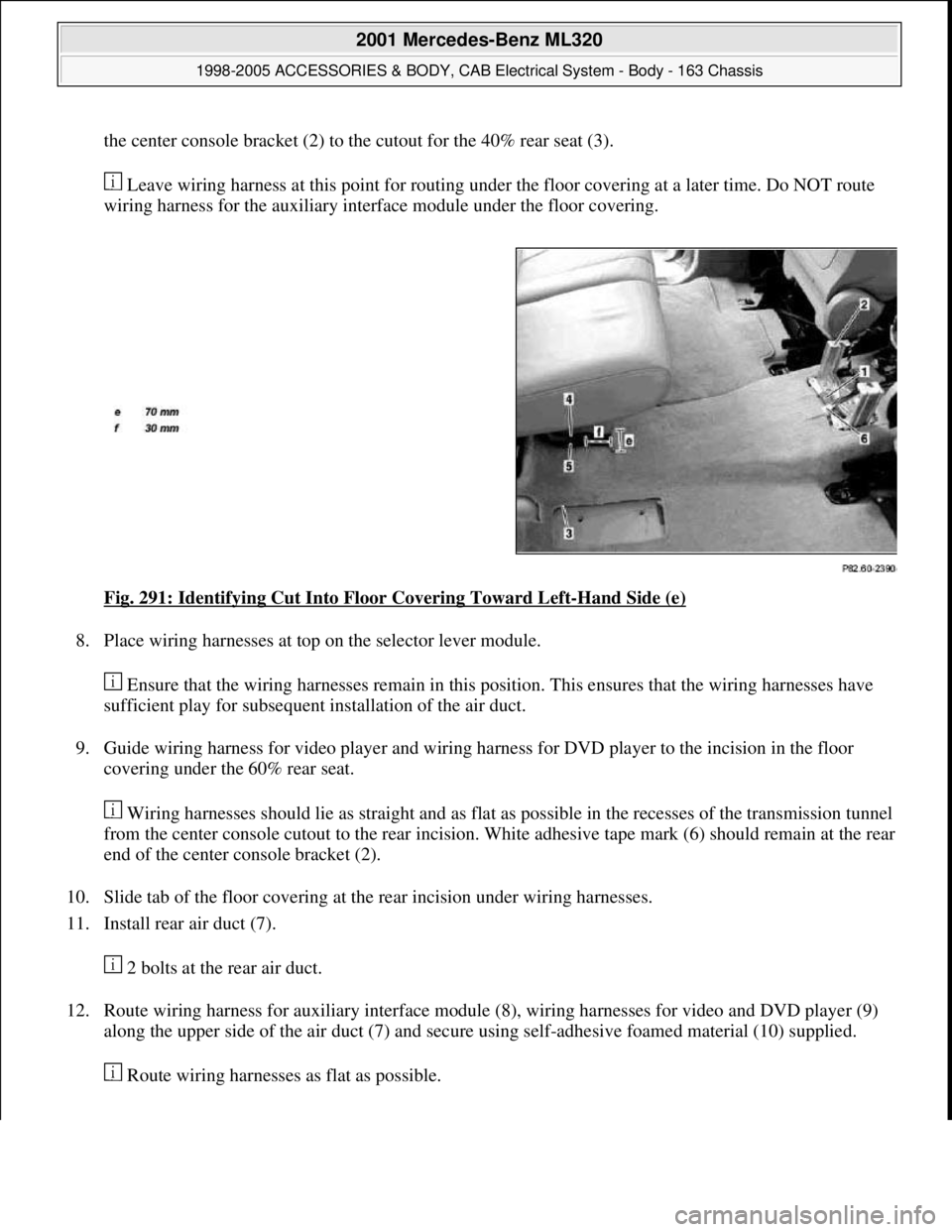
the center console bracket (2) to the cutout for the 40% rear seat (3).
Leave wiring harness at this point for routing under the floor covering at a later time. Do NOT route
wiring harness for the auxiliary interface module under the floor covering.
Fig. 291: Identifying Cut Into Floor Covering Toward Left
-Hand Side (e)
8. Place wiring harnesses at top on the selector lever module.
Ensure that the wiring harnesses remain in this position. This ensures that the wiring harnesses have
sufficient play for subsequent installation of the air duct.
9. Guide wiring harness for video player and wiring harness for DVD player to the incision in the floor
covering under the 60% rear seat.
Wiring harnesses should lie as straight and as flat as possible in the recesses of the transmission tunnel
from the center console cutout to the rear incision. White adhesive tape mark (6) should remain at the rear
end of the center console bracket (2).
10. Slide tab of the floor covering at the rear incision under wiring harnesses.
11. Install rear air duct (7).
2 bolts at the rear air duct.
12. Route wiring harness for auxiliary interface module (8), wiring harnesses for video and DVD player (9)
along the upper side of the air duct (7) and secure using self-adhesive foamed material (10) supplied.
Route wirin
g harnesses as flat as possible.
2001 Mercedes-Benz ML320
1998-2005 ACCESSORIES & BODY, CAB Electrical System - Body - 163 Chassis
me
Saturday, October 02, 2010 3:30:12 PMPage 377 © 2006 Mitchell Repair Information Company, LLC.
Page 1875 of 4133
Fig. 295: Identifying Dimension (b=510 mm) From Center Of Rear Blower Motor (M2/1)
3. Starting at the marking cut the floor lining towards the left-hand side of the vehicle (d=70 mm).
The incision should be located in the center of the transmission tunnel.
4. Cut floor lining from center of previous incision (d=70 mm) to vehicle rear (e=30 mm).
5. Route wiring harness video player (2) and wiring harness DVD player (3) from the incision to the rear of
the rear blower motor (M2/1) to the cutout in the floor lining under the 40% rear seat under the floor
lining.
Put down wiring harness for later routing.
Do not route wirin
g harness for additional interface module under the floor lining.
2001 Mercedes-Benz ML320
1998-2005 ACCESSORIES & BODY, CAB Electrical System - Body - 163 Chassis
me
Saturday, October 02, 2010 3:30:12 PMPage 380 © 2006 Mitchell Repair Information Company, LLC.
Page 1903 of 4133
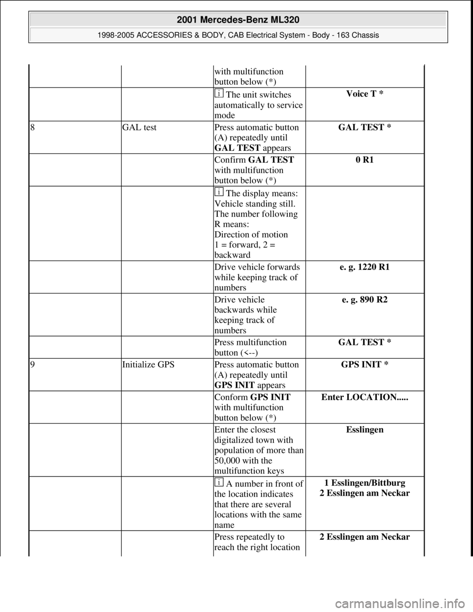
with multifunction
button below (*)
The unit switches
automatically to service
modeVoice T *
8GAL testPress automatic button
(A) repeatedly until
GAL TEST appearsGAL TEST *
Confirm GAL TEST
with multifunction
button below (*)0 R1
The display means:
Vehicle standing still.
The number following
R means:
Direction of motion
1 = forward, 2 =
backward
Drive vehicle forwards
while keeping track of
numberse. g. 1220 R1
Drive vehicle
backwards while
keeping track of
numberse. g. 890 R2
Press multifunction
button (<--)GAL TEST *
9Initialize GPSPress automatic button
(A) repeatedly until
GPS INIT appearsGPS INIT *
Conform GPS INIT
with multifunction
button below (*)Enter LOCATION.....
Enter the closest
digitalized town with
population of more than
50,000 with the
multifunction keysEsslingen
A number in front of
the location indicates
that there are several
locations with the same
name1 Esslingen/Bittburg
2 Esslingen am Neckar
Press repeatedly to
reach the right location 2 Esslingen am Neckar
2001 Mercedes-Benz ML320
1998-2005 ACCESSORIES & BODY, CAB Electrical System - Body - 163 Chassis
me
Saturday, October 02, 2010 3:30:13 PMPage 408 © 2006 Mitchell Repair Information Company, LLC.