Page 3874 of 4133
REMOVING AND INSTALLING ACCELERATOR PEDAL - AR30.12-P-1321GH
ENGINE 111.977 in MODEL 163.136
ENGINE 112.942 in MODEL 163.154
ENGINE 112.970 in MODEL 163.157
ENGINE 113.981 in MODEL 163.174
6Push control cable (32) from vehicle interior
towards the outside Do not push rubber grommet out
of splash wall.
7Remove entire control cable (32) from engine
compartment
8Install in the reverse order
9Check throttle control, adjust
Engine 112.942/970,
113.942/965/981 ?
Automatic transmissionAR30.10-P-
1010GJ
Engine 612.963: ?
Manual/automatic transmissionAR30.10-P-
1010GH
Engine 628.963: ?
Automatic transmissionAR30.10-P-
1010GH
2001 Mercedes-Benz ML320
1998-2005 ACCESSORIES & BODY CAB Throttle Control, Speed Control Systems - 163 Chassis
me
Saturday, October 02, 2010 3:36:28 PMPage 34 © 2006 Mitchell Repair Information Company, LLC.
Page 3891 of 4133

Fig. 4: Connecting Hand Held Tester Scan Tool To OBD-II Data Link Connector
Courtesy of MERCEDES-BENZ OF NORTH AMERICA.
TESTING
Starter malfunctions may cause a Di agnostic Trouble Codes (DTCs) to be stored in Motor Electronics
Sequential Fuel Injection (ME-SFI) sy stem. After repairs are completed check for and erase any DTCs stored in
(ME-SFI) system. See appropriate SE LF-DIAGNOSTICS article in ENGINE PERFORMANCE. If cause of
starter malfunction is not engine pe rformance related, replace starter.
REMOVAL & INSTALLATION
STARTER
Removal & Installation
1. Disconnect and shield negative battery cable. See BATTERY DISCONNECT/CONNECT under
SERVICE PRECAUTIONS.
2. Remove nut (2) for inner fender. See Fig. 5
. Pull front and rear section of inner fender (1) downward.
Move inner fender away inward and downward. Pull toward outside over wheel. DO NOT damage fender
cutout or paint.
3. On vehicles with 112 engine, remove nut (6) at shield (5) of left engine mount and take out shield. See
Fig. 6
.
4. On all vehicles, disconnect circuit 30 (1) and circuit 50 (2) cables from starter. See Fig. 6
. Remove bolts
(3) for starter-to-crankcase. Take starter (M1) out to the side.
5. If replacing starter on vehicles with manual transmission, check ring gear at flywheel for wear and
damage. If replacing starter on vehicles with auto matic transmission, check ring gear on drive plate for
wear and damage. Repair or repl ace damaged parts as necessary.
6. To install, reverse removal proce dure. Replace bolts with locking splines, micro-encapsulated bolts and
self-locking nuts. Mating thread of mi cro-encapsulated bolts must be cleaned to remove all residue of old
bolt locking compound. Tighten fasteners to specification. See TORQUE SPECIFICATIONS
. Connect
battery. See BATTERY DISCONNECT/CONNECTunder SERVICE PRECAUTIONS.
NOTE: Numbers and letters in text refe
r to numbers and letters in figures.
2001 Mercedes-Benz ML320
2001-04 STARTING & CHARGING SYSTEMS Starters - 163 Chassis
me
Saturday, October 02, 2010 3:19:47 PMPage 9 © 2006 Mitchell Repair Information Company, LLC.
Page 3907 of 4133

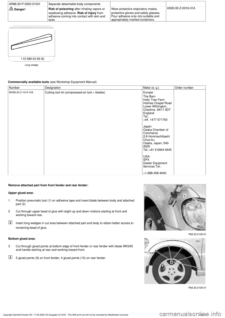
AR88.30-P-0200-01GH
Separate detachable body components
Danger!
Risk of poisoning
after inhaling vapors or
swallowing adhesive.
Risk of injury
from
adhesive coming into contact with skin and
eyes
Wear protective respiratory masks,
protective gloves and safety glasses.
Pour adhesive only into suitable and
appropriately marked containers.
AS00.00-Z-0016-01A
Long wedge
115 589 03 59 00
Commercially available tools
(see Workshop Equipment Manual)
Number
Designation
Make (e. g.)
Order number
WH58.30-Z-1010-10A
Cutting tool kit (compressed-air tool + blades)
Europe:
The Barn
Holly Tree Farm
Holmes Chapel Road
Lower Withington,
Cheshire, SK11 9DT
England
Tel.:
+44 1477 571700
Japan:
Osaka Chamber of
Commerce
2-8 Hommachibashi
Chuo-ku
Osaka, Japan, 540-
0029
Tel.:+81 6 6944 6445
USA:
SPX
Dealer Equipment
Services Tel.:
+1-888-458-4040
P88.30-2108-01
Remove attached part from front fender and rear fender:
Upper glued area:
1
Position pneumatic tool (1) on adhesive tape and insert blade between body and attached
part (2).
2
Cut through upper bead of glue with slight up and down motions starting at front and
working toward rear.
Insert long wedges in cut area between attached part and body to obtain better access to
remaining bead of glue.
P88.30-2109-01
Bottom glued area:
3
Cut through glued points at bottom edge of front fender or rear fender with blade WK24S
and handle starting at rear and working toward front.
5 glued points (9) on front fender, 4 glued points (10) on rear fender.
Copyright DaimlerChrysler AG 17.05.2006 CD-Ausgabe G/10/04 . This WIS print-out will not be recorde
d by Modification services.
Page 1