Page 1494 of 4133

AR91.12-P-1010GI
Remove and install bench
21.3.00
MODELS
163.136 /154 /172 as of 1.9.99,
163.113 /128 /157 /174 /175
40 % bench seat
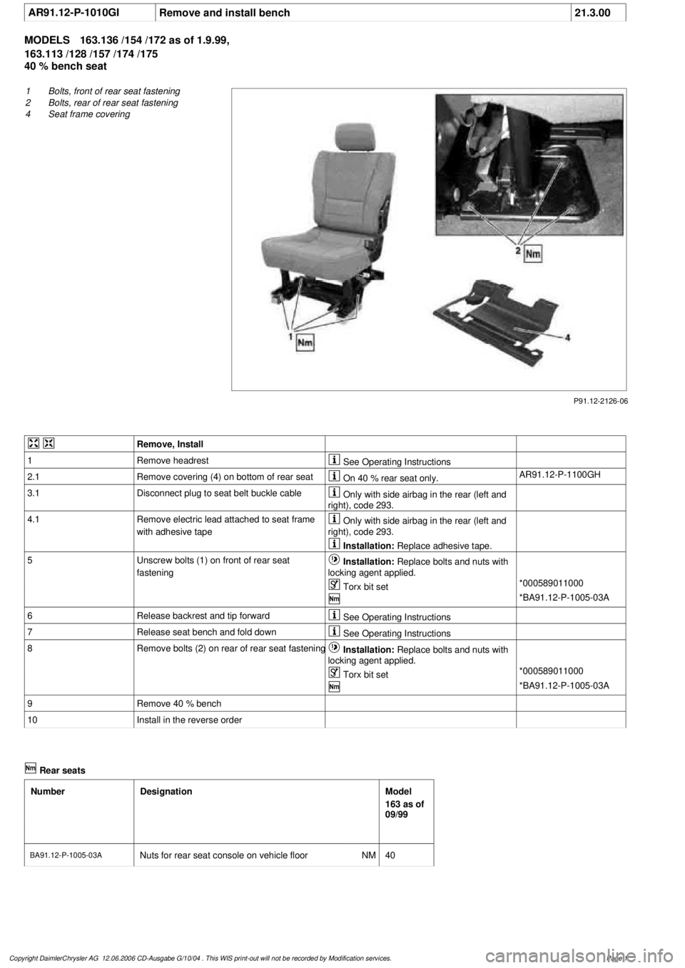
P91.12-2126-06
1
Bolts, front of rear seat fastening
2
Bolts, rear of rear seat fastening
4
Seat frame covering
Remove, Install
1
Remove headrest
See Operating Instructions
2.1
Remove covering (4) on bottom of rear seat
On 40 % rear seat only.
AR91.12-P-1100GH
3.1
Disconnect plug to seat belt buckle cable
Only with side airbag in the rear (left and
right), code 293.
4.1
Remove electric lead attached to seat frame
with adhesive tape
Only with side airbag in the rear (left and
right), code 293.
Installation:
Replace adhesive tape.
5
Unscrew bolts (1) on front of rear seat
fastening
Installation:
Replace bolts and nuts with
locking agent applied.
Torx bit set
*000589011000
*BA91.12-P-1005-03A
6
Release backrest and tip forward
See Operating Instructions
7
Release seat bench and fold down
See Operating Instructions
8
Remove bolts (2) on rear of rear seat fastening
Installation:
Replace bolts and nuts with
locking agent applied.
Torx bit set
*000589011000
*BA91.12-P-1005-03A
9
Remove 40 % bench
10
Install in the reverse order
Rear seats
Number
Designation
Model
163 as of
09/99
BA91.12-P-1005-03A
Nuts for rear seat console on vehicle floor
NM
40
Copyright DaimlerChrysler AG 12.06.2006 CD-Ausgabe G/10/04 . This WIS print-out will not be recorde
d by Modification services.
Page 1
Page 3582 of 4133
Fig. 66: Identifying Headliner Components
Remove/install
1Remove headrest See owner's manual
2Remove inside rearview
mirror (13) To vehicle identification number A145272,
X708318.AR68.40-P-
0001GH
As of vehicle identification number A145273,
X708319.AR68.40-P-
0001GI
3Remove front overhead
control panel (1) AR82.20-P-
1100GH
4Remove front roof frame
handles (2)
Up to 31.08.01: Open covers for handles, press
clip for handle down on each side, simultaneously
press handle upward and pull out.
As of 01.09.01: Open cover and unscrew screws.
Up to 31.08.01: With integral rear dome lamp.
Open covers for handles, press clip for handle down
2001 Mercedes-Benz ML320
1998-2005 ACCESSORIES & BODY, CAB Interior Equipment - 163 Chassis
me
Saturday, October 02, 2010 3:35:22 PMPage 64 © 2006 Mitchell Repair Information Company, LLC.
Page 3795 of 4133

AR91.18-P-1820GH
Remove front seat backrest cover
30.4.97
MODEL
163.113 /128 /136 /154 /157 /172 /174 /175
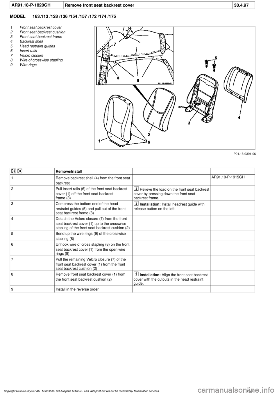
P91.18-0394-06
1
Front seat backrest cover
2
Front seat backrest cushion
3
Front seat backrest frame
4
Backrest shell
5
Head restraint guides
6
Insert rails
7
Velcro closure
8
Wire of crosswise stapling
9
Wire rings
Remove/Install
1
Remove backrest shell (4) from the front seat
backrest
AR91.10-P-1915GH
2
Pull insert rails (6) of the front seat backrest
cover (1) off the front seat backrest
frame (3)
Relieve the load on the front seat backrest
cover by pressing down the front seat
backrest frame.
3
Compress the bottom end of the head
restraint guides (5) and pull out of the front
seat backrest frame (3)
Installation:
Install headrest guide with
release button on the left.
4
Detach the Velcro closure (7) from the front
seat backrest cover (1) up to the crosswise
stapling of the front seat backrest cushion (2)
5
Bend up the wire rings (9) of the crosswise
stapling (8)
6
Unhook wire of cross stapling (8) on the front
seat backrest cover (1) from the open wire
rings (9)
7
Pull the remaining Velcro closure (7) of the
front seat backrest cover (1) from the front
seat backrest cushion (2)
8Remove front seat backrest cover (1) from
the front seat backrest cushion (2)
Installation:
Align the front seat backrest
cover with the cutouts in the head restraint
guide.
9
Install in the reverse order
Copyright DaimlerChrysler AG 14.06.2006 CD-Ausgabe G/10/04 . This WIS print-out will not be recorde
d by Modification services.
Page 1
Page 3803 of 4133

AR91.10-P-1000GH
Remove/install front seat
3.3.97
MODEL
163.113 /128 /136 /154 /157 /172 /174 /175 with CODE (221b) Electrically adjustable driver and passe
nger seat
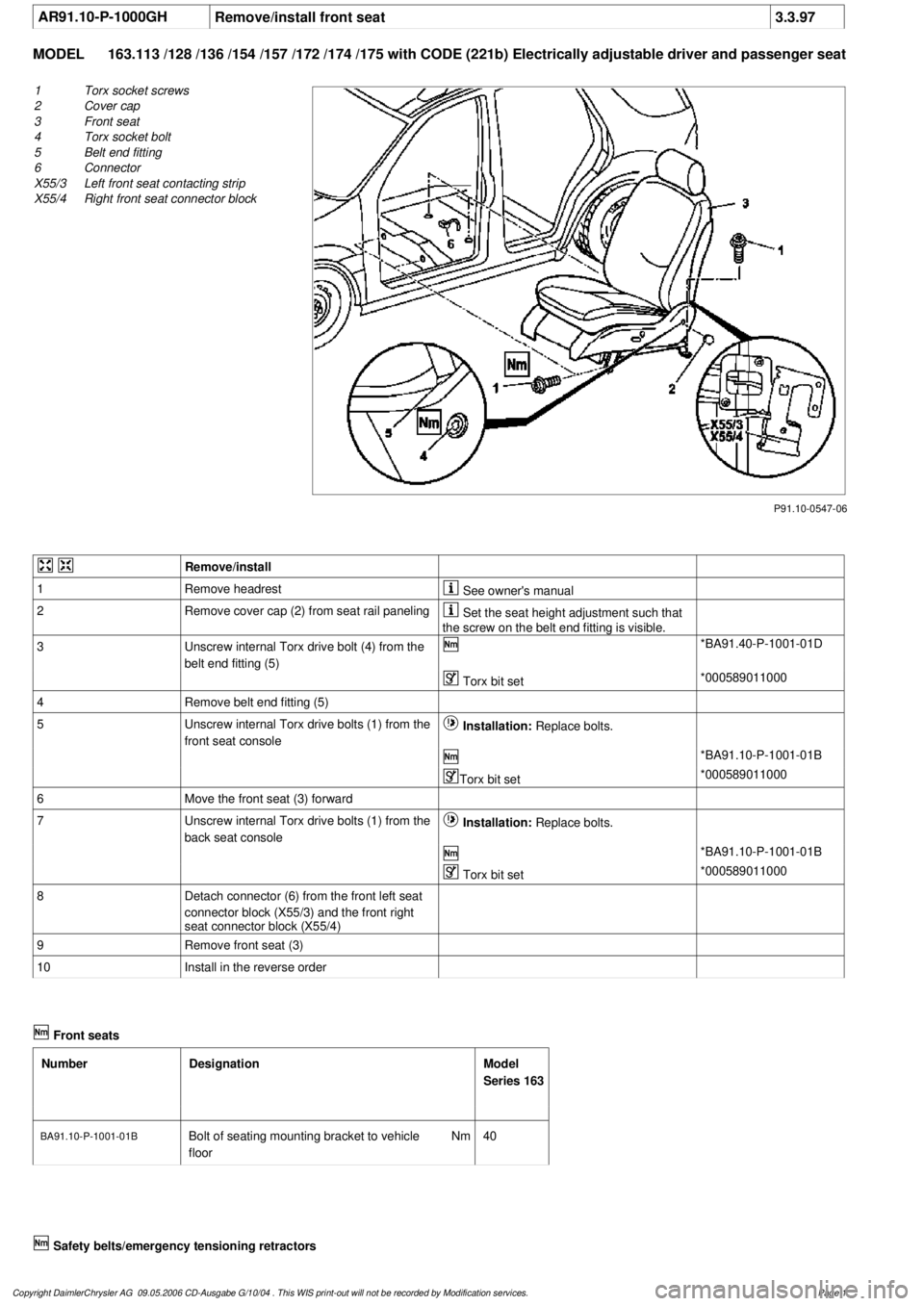
P91.10-0547-06
1
Torx socket screws
2
Cover cap
3
Front seat
4
Torx socket bolt
5
Belt end fitting
6
Connector
X55/3
Left front seat contacting strip
X55/4
Right front seat connector block
Remove/install
1
Remove headrest
See owner's manual
2
Remove cover cap (2) from seat rail paneling
Set the seat height adjustment such that
the screw on the belt end fitting is visible.
3
Unscrew internal Torx drive bolt (4) from the
belt end fitting (5)
*BA91.40-P-1001-01D
Torx bit set
*000589011000
4
Remove belt end fitting (5)
5
Unscrew internal Torx drive bolts (1) from the
front seat console
Installation:
Replace bolts.
*BA91.10-P-1001-01B
Torx bit set
*000589011000
6
Move the front seat (3) forward
7
Unscrew internal Torx drive bolts (1) from the
back seat console
Installation:
Replace bolts.
*BA91.10-P-1001-01B
Torx bit set
*000589011000
8
Detach connector (6) from the front left seat
connector block (X55/3) and the front right
seat connector block (X55/4)
9
Remove front seat (3)
10
Install in the reverse order
Front seats
Number
Designation
Model
Series 163
BA91.10-P-1001-01BBolt of seating mounting bracket to vehicle
floor
Nm
40
Safety belts/emergency tensioning retractors
Copyright DaimlerChrysler AG 09.05.2006 CD-Ausgabe G/10/04 . This WIS print-out will not be recorde
d by Modification services.
Page 1
Page 3813 of 4133

AR91.12-P-1720GI
Remove/install tilting rear seat
3.5.99
MODEL
163.136 /154 /172 as of 1.9.99,
163.113 /128 /157 /174 /175
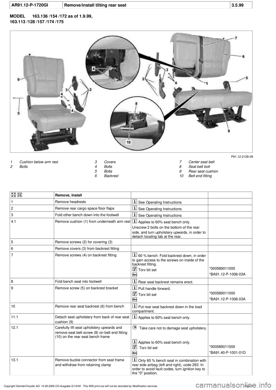
P91.12-2128-09
1
Cushion below arm rest
2
Bolts
7
Center seat belt
8
Seat belt bolt
9
Rear seat cushion
10
Belt end fitting
3
Covers
4
Bolts
5
Bolts
6
Backrest
Remove, Install
1
Remove headrests
See Operating Instructions
2
Remove rear cargo space floor flaps
See Operating Instructions
3
Fold other bench down into the footwell
See Operating Instructions
4.1
Remove cushion (1) from underneath arm rest
Applies to 60% seat bench only.
Unscrew 2 bolts on the bottom of the rear
side, and turn upholstery upwards, in order to
detach locating tab at the rear.
5
Remove screws (2) for covering (3)
6
Remove covers (3) from backrest fitting
7
Remove screws (4) on backrest fitting
60 % bench: Fold backrest down, in order
to gain access to the screws on inside of the
backrest fitting.
Torx bit set
*000589011000
*BA91.12-P-1006-03A
8
Fold bench seat into footwell
Rear seat backrest remains erect.
9
Remove screw (5) on backrest bracket
Pull handle forward.
Torx bit set
*000589011000
*BA91.12-P-1006-03A
10
Remove rear seat backrest (6) from bench
Put rear seat backrest down in the load
compartment.
11.1
Detach seat upholstery from back of rear seat
cushion (9)
Applies to 60% seat bench only.
12.1
Carefully lift seat upholstery upwards and
remove seat belt screw (8) on belt end fitting
(10) on the rear seat bench frame
Take care not to damage seat upholstery.
Applies to 60% seat bench only.
Torx bit set
*000589011000
*BA91.40-P-1001-01D
13.1
Remove buckle connector from seat frame
and withdraw from retaining clamp
Only 60 % bench seat in combination with
rear side airbag (left and right), code 293. In
order to avoid fault codes, turn ignition key to
the "0" position.
Copyright DaimlerChrysler AG 14.06.2006 CD-Ausgabe G/10/04 . This WIS print-out will not be recorde
d by Modification services.
Page 1