1997 MERCEDES-BENZ ML500 tow
[x] Cancel search: towPage 3731 of 4133
AR88.70-P-9040GI
Remove/install outside rearview mirror paneling
27.2.01
MODEL
163.113 /154 /174 #A as of 289565,
163.113 /154 /174 #X as of 754620,
163.128 /157 /175
P88.70-2107-11
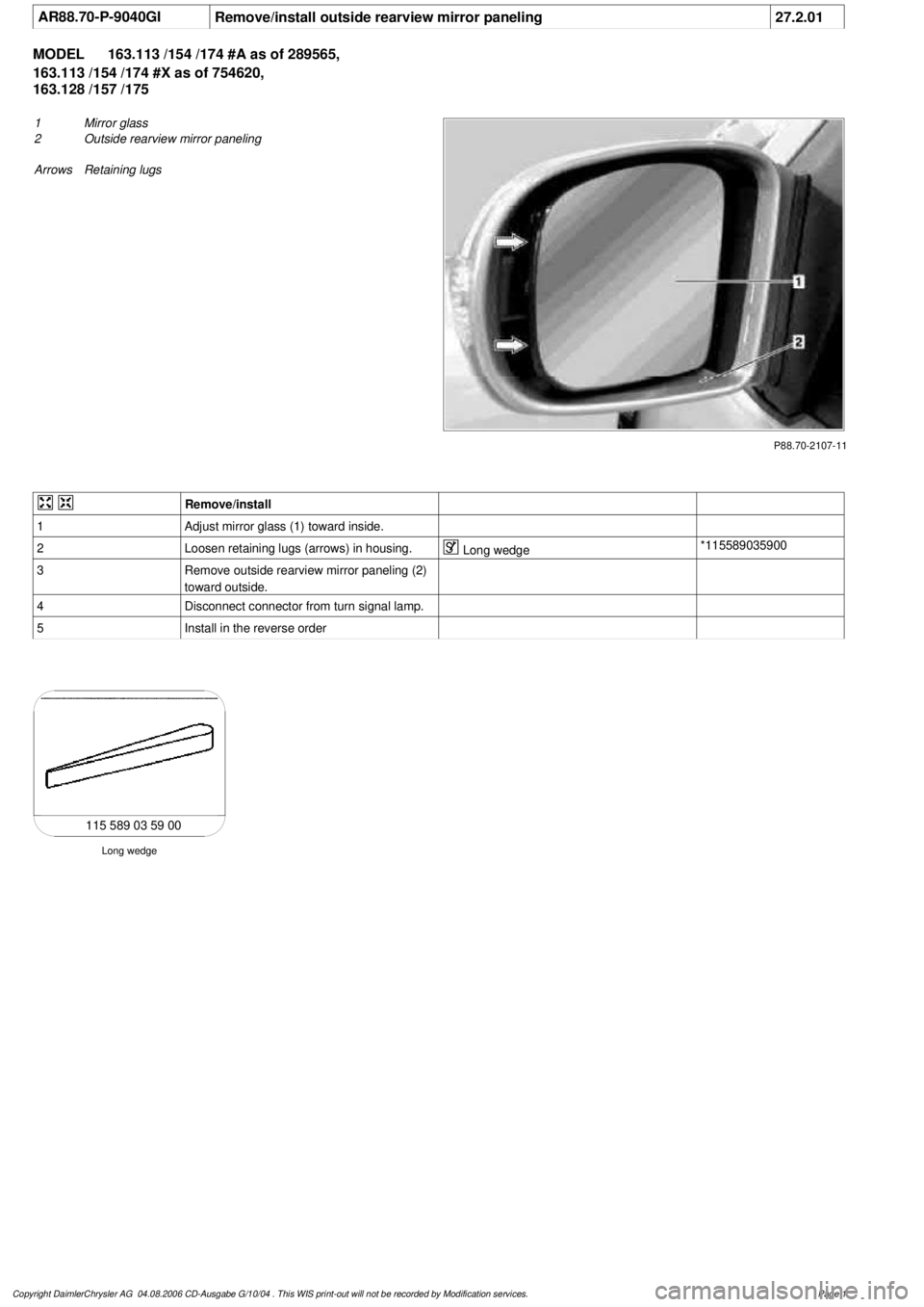
1
Mirror glass
2
Outside rearview mirror paneling
Arrows Retaining lugs
Remove/install
1
Adjust mirror glass (1) toward inside.
2
Loosen retaining lugs (arrows) in housing.
Long wedge
*115589035900
3
Remove outside rearview mirror paneling (2)
toward outside.
4
Disconnect connector from turn signal lamp.
5
Install in the reverse order
Long wedge
115 589 03 59 00
Copyright DaimlerChrysler AG 04.08.2006 CD-Ausgabe G/10/04 . This WIS print-out will not be recorde
d by Modification services.
Page 1
Page 3732 of 4133
AR88.70-P-9040GH
Removing and installing outside rearview mirror cover
12.2.97
MODEL
163.113 /136 /154 /172 /174 up to 31.8.01
P88.70-0255-06
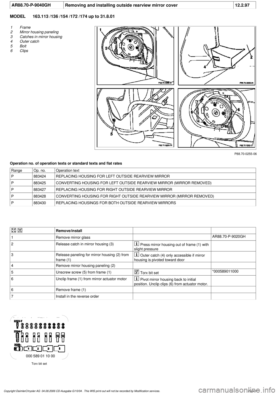
1
Frame
2
Mirror housing paneling
3
Catches in mirror housing
4
Outer catch
5
Bolt
6
Clips
Operation no. of operation texts or standard texts and flat rates
Range
Op. no.
Operation text
P
883424
REPLACING HOUSING FOR LEFT OUTSIDE REARVIEW MIRROR
P
883425
CONVERTING HOUSING FOR LEFT OUTSIDE REARVIEW MIRROR (MIRROR REMOVED)
P
883427
REPLACING HOUSING FOR RIGHT OUTSIDE REARVIEW MIRROR
P
883428
CONVERTING HOUSING FOR RIGHT OUTSIDE REARVIEW MIRROR (MIRROR REMOVED)
P
883430
REPLACING HOUSINGS FOR BOTH OUTSIDE REARVIEW MIRRORS
Remove/install
1
Remove mirror glass
AR88.70-P-9020GH
2
Release catch in mirror housing (3)
Press mirror housing out of frame (1) with
slight pressure
3
Release paneling for mirror housing (2) from
frame (1)
Outer catch (4) only accessible if mirror
housing is pivoted toward door
4
Remove mirror housing paneling (2)
5
Unscrew screw (5) from frame (1)
Torx bit set
*000589011000
6
Unclip frame (1) from mirror actuator motor
Pivot mirror housing back to initial
position. Unclip clips (6) from actuator motor.
6
Remove frame (1)
7
Install in the reverse order
Torx bit set
000 589 01 10 00
Copyright DaimlerChrysler AG 04.08.2006 CD-Ausgabe G/10/04 . This WIS print-out will not be recorde
d by Modification services.
Page 1
Page 3742 of 4133
AR03.10-P-7311BV
Remove/install piston rings
2.7.97
ENGINE
113 in MODEL 129, 163, 202, 203, 208, 209, 210, 211, 215, 220, 230
ENGINE
112 /945, 113.962 /982
P03.10-2022-06
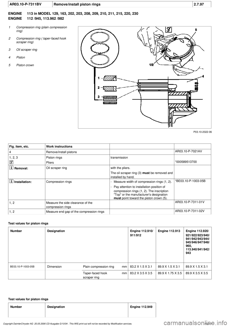
1
Compression ring (plain compression
ring)
2
Compression ring ( taper-faced hook
scraper ring)
3
Oil scraper ring
4
Piston
5
Piston crown
Fig. item, etc.
Work instructions
4
Remove/install pistons
AR03.10-P-7021AV
1, 2, 3
Piston rings
transmission
Pliers
*000589513700
Removal:
Oil scraper ring
with the pliers.
The oil scraper ring (3)
must be removed and
installed by hand.
Installation:
Compression rings
-
Measure width of compression rings (1, 2).
*BE03.10-P-1003-05B
-
Pay attention to installation position of
compression rings (1, 2). The inscription
"Top" or the manufacturer's designation
must
point toward the piston crown (5).
1, 2
Measure the side clearance of the
compression rings
AR03.10-P-7311-01V
1, 2
Measure end gap of the compression rings
AR03.10-P-7311-02V
Test values for piston rings
Number
Designation
Engine 112.910/
911/912
Engine 112.913
Engine 112.920/
921/922/923/940/
941/942/943/944/
945/946/947/948/
960,
113.940/941/942/
943
BE03.10-P-1003-05B
Dimension
Plain compression ring
mm
83.2 X 1.5 X 3.189.9 X 1.5 X 3.189.9 X 1.5 X 3.1
Taper-faced hook
scraper ring
mm
83.2 X 3.5 X 3.5
89.9 X 1.75 X 3.5
89.9 X 3.5 X 3.5
Test values for piston rings
Number
Designation
Engine 112.949
Copyright DaimlerChrysler AG 20.05.2006 CD-Ausgabe G/10/04 . This WIS print-out will not be recorde
d by Modification services.
Page 1
Page 3759 of 4133
AR20.40-P-5000M
Remove/install electric fan
24.8.99
ENGINE
612.963 in MODEL 163.113
P20.40-2015-06
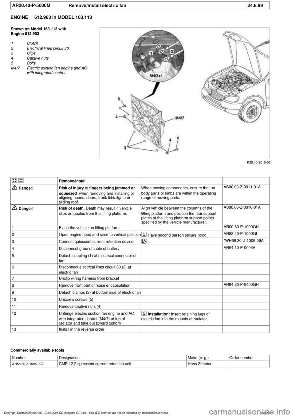
Shown on Model 163.113 with
Engine 612.963
1
Clutch
2
Electrical lines circuit 30
3
Clips
4
Captive nuts
5
Bolts
M4/7
Electric suction fan engine and AC
with integrated control
Remove/Install
Danger!
Risk of injury
to
fingers being jammed or
squeezed
when removing and installing or
aligning hoods, doors, trunk lid/tailgate or
sliding roof.
When moving components, ensure that no
body parts or limbs are within the operating
range of moving parts.
AS00.00-Z-0011-01A
Danger!
Risk of death.
Death may result if vehicle
slips or topples from the lifting platform.
Align vehicle between the columns of the
lifting platform and position the four support
plates
at the lifting platform support points
specified by the vehicle manufacturer.
AS00.00-Z-0010-01A
1
Place the vehicle on lifting platform
AR00.60-P-1000GH
2
Open engine hood and raise to vertical position
Have second person secure hood.
AR88.40-P-1000GI
3
Connect quiescent current retention device
*WH58.30-Z-1005-09A
4
Disconnect ground cable of battery
AR54.10-P-0003A
5
Detach coupling (1) at electrical connector of
fan
6
Disconnect electrical lines circuit 30 (2) at
electric fan
7
Unclip wiring harness from bracket
8
Remove front part of noise encapsulation
AR94.30-P-5400GH
9
Detach clamps (3) at bottom side of electric fan
10
Unscrew screws (5)
11
Remove captive nuts (4)
12
Unhinge electric suction fan engine and AC
with integrated control (M4/7) at top of
radiator and take out toward bottom
Installation:
Insert retaining lugs of
electric fan into the mounts at radiator.
13
Install in the reverse order
Commercially available tools
Number
Designation
Make (e. g.)
Order number
WH58.30-Z-1005-09A
CMP 12.2 quiescent current retention unit
Hans Zeheter
Copyright DaimlerChrysler AG 12.05.2006 CD-Ausgabe G/10/04 . This WIS print-out will not be recorde
d by Modification services.
Page 1
Page 3761 of 4133

Danger!
Risk of injury
to skin and eyes suffering
scalding from contact with hot coolant spray.
Risk of poisoning
from swallowing coolant.
Do not open cooling system unless coolant
temperature is below 90 °C. Open cap slowly
and release the pressure. Do not pour coolant
into beverage bottles.
Wear protective gloves, protective clothing
and eye protection.
AS20.00-Z-0001-01A
1
Open engine hood and raise to vertical position
Have second person secure hood.
AR88.40-P-1000GI
2
Connect no load current retention unit
*WH58.30-Z-1005-09A
3
Disconnect battery ground cable
AR54.10-P-0003A
4
Remove trim panel of cylinder head cover
AR01.20-P-5014-02B
*BA01.20-P-1002-01A
*BA01.20-P-1003-01A
5
Remove bottom part of noise encapsulation
at front
AR94.30-P-5400GH
6
Remove electric fan (1)
Remove toward bottom.
AR20.40-P-5000M
7
Drain coolant
At radiator.
AR20.00-P-1142M
Notes on coolant
All engines
AH20.00-N-2080-01A
8
Remove charge air cooler (110/2)
AR09.41-P-6817MM
9.1
Attach guard plate for radiator/condenser
With automatic air conditioning, code
581a and AC system or Tempmatic USA,
code 580.
Attach additional AC condenser in the
vehicle.
y
Guard plate for radiator/condenser
Engine 606 in model 124,
Engine 606.961 in model 140,
Engine 112, 113, 604, 605, 611.960 in
MODEL 202,
Engine 602.983, 612.966 in MODEL 461,
Engine 628.962, 612.965, 606.964, 112.945,
113.962/ 982 in MODEL 463,
Engine 111, 112, 611.962, 612.962 in model
203,
Engines 112, 113, 611.961, 612.961, 613.961
in MODEL 210,
Engine 112 in model 170,
Engine 112 in MODEL 220,
Engine 113 in MODEL 211, 215, 220,
Engine 112 in MODEL 208,
Engine 112, 612.963, 628.963 in MODEL 163,
Engine 112.923 /943, 113.961 in MODEL 129,
Engine 137, 275 in MODEL 215, 220,
Engine 613.960, 628.960 in MODEL 220,
Engine 113.992 in model 230.474,
Engine 271 in model 209, 203,
Engine 285.950 in model 240.078 /178,
Engine 612.967 in model 209.316,
Engine 648 in model 220
Engine 112.951 in model 639.601/603/
605/701/703/705/801/803/805
Engine 646.983/984 in model 639.601/
603/605/701/703/705/801/803/805
Engine 646.982 in model
639.601/603/605/701/703/705
WF58.50-P-0110-01A
10
Remove seal rail (11)
11
Extract steering oil from reservoir
Hand pump
*210589007100
12.1
Disconnect power steering oil line (return line
radiator
!
power steering pump supply
reservoir) (18)
Seal connections.
Installation:
Install new sealing rings.
*BA46.30-P-1012-01A
Clamp
*000589543700
Set of stop plugs
*129589009100
12.2
Disconnect power steering oil line (feed line of
steering gear
!
radiator) (19)
Clamp
*000589543700
Set of stop plugs
*129589009100
Hexagon socket wrench
*WH58.30-Z-1001-06A
Hexagon socket wrench
*WH58.30-Z-1002-06A
Copyright DaimlerChrysler AG 12.05.2006 CD-Ausgabe G/10/04 . This WIS print-out will not be recorde
d by Modification services.
Page 2
Page 3783 of 4133
13
Mark floor pan through center of rivet and bolt
locations (12, 13) for anchor mounting plate (2)
Only for those positions at which anchor
rings will be installed.
14
Remove template (1)
15
At marks, drill Ø=9.5 mm hole (10) for anchor
bolt and Ø=4 mm holes (11) for rivets
Model 163.174: To avoid damaging
auxiliary fuel tank, do not drill more than 5mm
through floor pan for 2nd row center anchor
ring.
16
Smooth rough edges of holes on underside of
floor pan
17
Clean, prime, and paint holes
18
Using an assistant, place mounting plate (2)
into position from underneath vehicle and
secure with bolt (8)
Plate should be flush with surface of body.
19
Rivet plate into position from inside vehicle,
then remove bolt (8)
20
Seal underbody at plate location
Body seam sealant
*BR00.45-Z-1004-01A
Installing
21
Install load compartment floor covering
Do NOT install internal spare on Model
163.174 at this time.
f
AR68.20-P-4810GH
22
Loosely install trim plate (5) to observe fit to
floor covering
Straight edge of plate (5) towards front of
vehicle.
23
Remove trim plate (5) and relieve floor
covering so that plate, when installed, is
completely flush with floor covering
Use caution to avoid making hole too
large for trim plate to cover hole completely.
Square off hole at front. Relieve only down to
foam.
24
Install anchor ring (6) and related components
Use short spacer (4) on 3rd row rings.
Use long spacer (3) on 2nd row outboard
rings. Use short bolt (8) and no spacer on 2nd
row center ring.
Torx bit set
*000589011000
*BA68.50-P-1001-02A
25
Reinstall rear axle carrier
Model 163.174 only.
f
AR35.10-P-0020-01GH
26
Reinstall internal spare tire and carrier
Model 163.174 only.
f
AR68.30-P-4610GH
27
Reinstall compact spare tire
See Owner's Manual.
Luggage nets
Number
Designation
Model 163
BA68.50-P-1001-02A
Screw for cargo anchoring mount on load
compartment floor
Nm
24
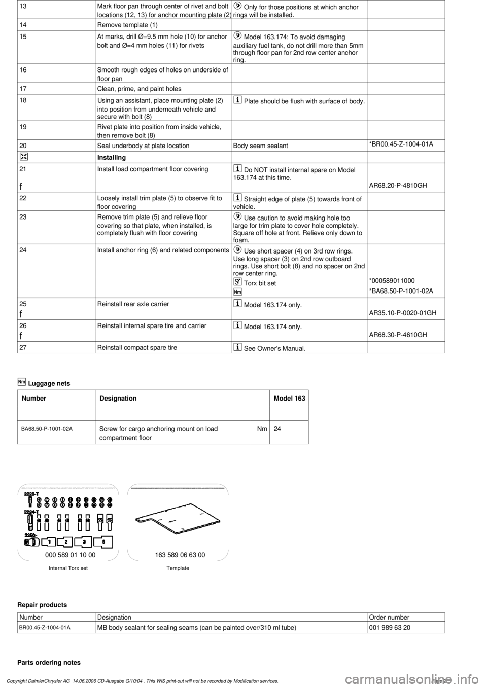
163 589 06 63 00
Template
Internal Torx set
000 589 01 10 00
Repair products
Number
Designation
Order number
BR00.45-Z-1004-01A
MB body sealant for sealing seams (can be painted over/310 ml tube)
001 989 63 20
Parts ordering notes
Copyright DaimlerChrysler AG 14.06.2006 CD-Ausgabe G/10/04 . This WIS print-out will not be recorde
d by Modification services.
Page 2
Page 3805 of 4133
AR91.12-P-1100GH
Remove and install cover on bottom of rear seat
22.2.00
MODELS
163.136 /154 /172 as of 1.9.99,
163.113 /128 /157 /174 /175
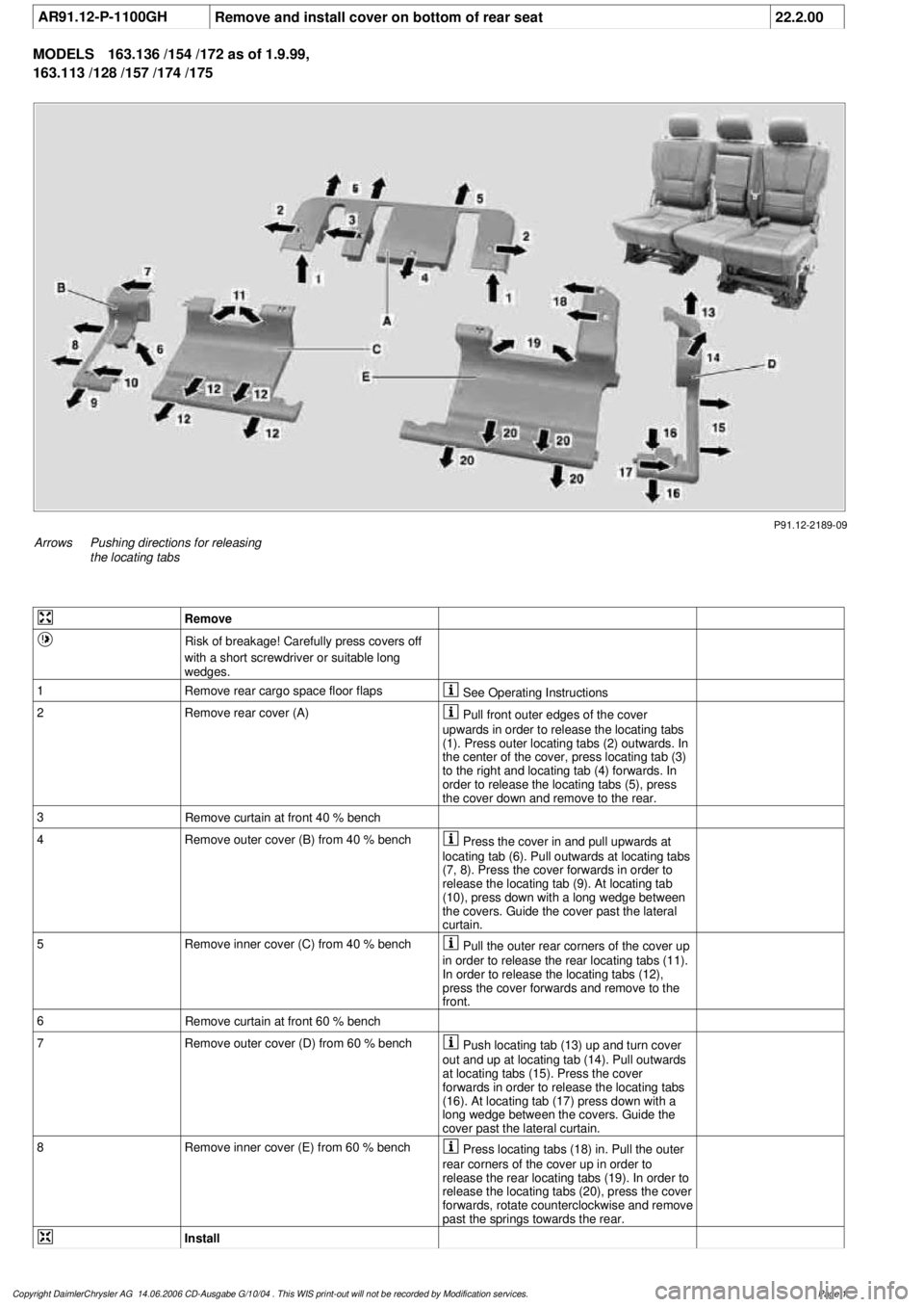
P91.12-2189-09
Arrows
Pushing directions for releasing
the locating tabs
Remove
Risk of breakage! Carefully press covers off
with a short screwdriver or suitable long
wedges.
1
Remove rear cargo space floor flaps
See Operating Instructions
2Remove rear cover (A)
Pull front outer edges of the cover
upwards in order to release the locating tabs
(1). Press outer locating tabs (2) outwards. In
the center of the cover, press locating tab (3)
to the right and locating tab (4) forwards. In
order to release the locating tabs (5), press
the cover down and remove to the rear.
3
Remove curtain at front 40 % bench
4
Remove outer cover (B) from 40 % bench
Press the cover in and pull upwards at
locating tab (6). Pull outwards at locating tabs
(7, 8). Press the cover forwards in order to
release the locating tab (9). At locating tab
(10), press down with a long wedge between
the covers. Guide the cover past the lateral
curtain.
5
Remove inner cover (C) from 40 % bench
Pull the outer rear corners of the cover up
in order to release the rear locating tabs (11).
In order to release the locating tabs (12),
press the cover forwards and remove to the
front.
6
Remove curtain at front 60 % bench
7
Remove outer cover (D) from 60 % bench
Push locating tab (13) up and turn cover
out and up at locating tab (14). Pull outwards
at locating tabs (15). Press the cover
forwards in order to release the locating tabs
(16). At locating tab (17) press down with a
long wedge between the covers. Guide the
cover past the lateral curtain.
8
Remove inner cover (E) from 60 % bench
Press locating tabs (18) in. Pull the outer
rear corners of the cover up in order to
release the rear locating tabs (19). In order to
release the locating tabs (20), press the cover
forwards, rotate counterclockwise and remove
past the springs towards the rear.
Install
Copyright DaimlerChrysler AG 14.06.2006 CD-Ausgabe G/10/04 . This WIS print-out will not be recorde
d by Modification services.
Page 1
Page 3837 of 4133
GF77.20-P-0001GH
Sliding /pop-up roof, function
28.2.97
MODEL
163 with CODE (414a) Electric glass sliding/pop-up roof
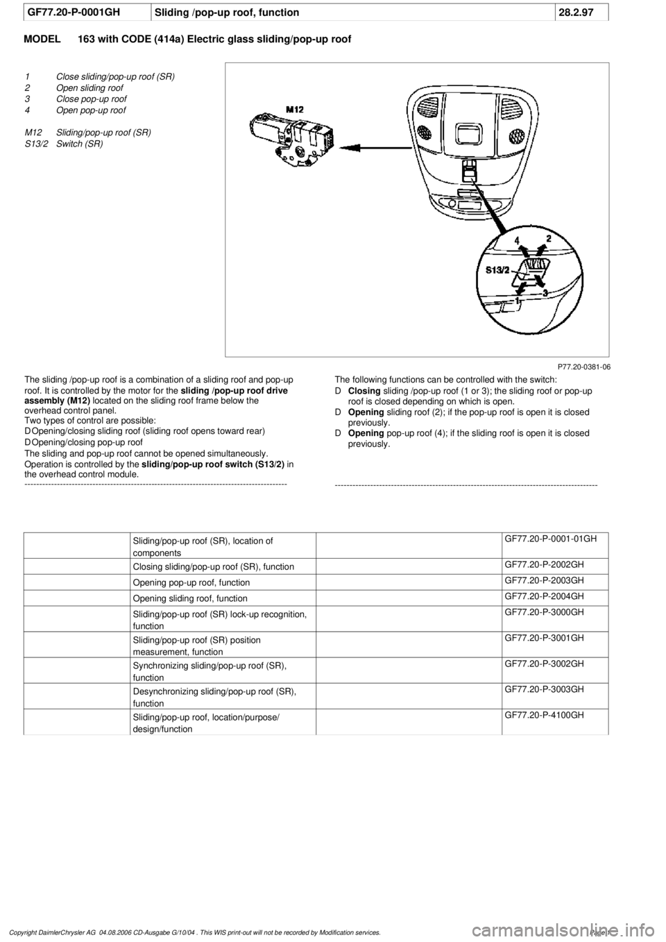
P77.20-0381-06
1
Close sliding/pop-up roof (SR)
2
Open sliding roof
3
Close pop-up roof
4
Open pop-up roof
M12
Sliding/pop-up roof (SR)
S13/2
Switch (SR)
The sliding /pop-up roof is a combination of a sliding roof and pop-up
roof. It is controlled by the motor for the
sliding /pop-up roof drive
assembly (M12)
located on the sliding roof frame below the
overhead control panel.
Two types of control are possible:
D
Opening/closing sliding roof (sliding roof opens toward rear)
D
Opening/closing pop-up roof
The sliding and pop-up roof cannot be opened simultaneously.
Operation is controlled by the
sliding/pop-up roof switch (S13/2)
in
the overhead control module.
-----------------------------------------------------------------------------------------
The following functions can be controlled with the switch:
D
Closing
sliding /pop-up roof (1 or 3); the sliding roof or pop-up
roof is closed depending on which is open.
D
Opening
sliding roof (2); if the pop-up roof is open it is closed
previously.
D
Opening
pop-up roof (4); if the sliding roof is open it is closed
previously.
-----------------------------------------------------------------------------------------
Sliding/pop-up roof (SR), location of
components
GF77.20-P-0001-01GH
Closing sliding/pop-up roof (SR), function
GF77.20-P-2002GH
Opening pop-up roof, function
GF77.20-P-2003GH
Opening sliding roof, function
GF77.20-P-2004GH
Sliding/pop-up roof (SR) lock-up recognition,
function
GF77.20-P-3000GH
Sliding/pop-up roof (SR) position
measurement, function
GF77.20-P-3001GH
Synchronizing sliding/pop-up roof (SR),
function
GF77.20-P-3002GH
Desynchronizing sliding/pop-up roof (SR),
function
GF77.20-P-3003GH
Sliding/pop-up roof, location/purpose/
design/function
GF77.20-P-4100GH
Copyright DaimlerChrysler AG 04.08.2006 CD-Ausgabe G/10/04 . This WIS print-out will not be recorde
d by Modification services.
Page 1