1997 MERCEDES-BENZ ML500 display
[x] Cancel search: displayPage 16 of 4133
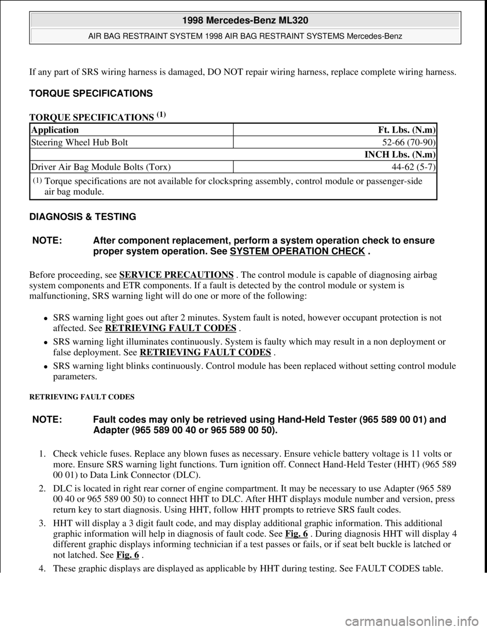
If any part of SRS wiring harness is damaged, DO NOT repair wiring harness, replace complete wiring harness.
TORQUE SPECIFICATIONS
TORQUE SPECIFICATIONS
(1)
DIAGNOSIS & TESTING
Before proceeding, see SERVICE PRECAUTIONS
. The control module is capable of diagnosing airbag
system components and ETR components. If a fault is detected by the control module or system is
malfunctioning, SRS warning light will do one or more of the following:
SRS warning light goes out after 2 minutes. System fault is noted, however occupant protection is not
affected. See RETRIEVING FAULT CODES
.
SRS warning light illuminates continuously. System is faulty which may result in a non deployment or
false deployment. See RETRIEVING FAULT CODES
.
SRS warning light blinks continuously. Control module has been replaced without setting control module
parameters.
RETRIEVING FAULT CODES
1. Check vehicle fuses. Replace any blown fuses as necessary. Ensure vehicle battery voltage is 11 volts or
more. Ensure SRS warning light functions. Turn ignition off. Connect Hand-Held Tester (HHT) (965 589
00 01) to Data Link Connector (DLC).
2. DLC is located in right rear corner of engine compartment. It may be necessary to use Adapter (965 589
00 40 or 965 589 00 50) to connect HHT to DLC. After HHT displays module number and version, press
return key to start diagnosis. Using HHT, follow HHT prompts to retrieve SRS fault codes.
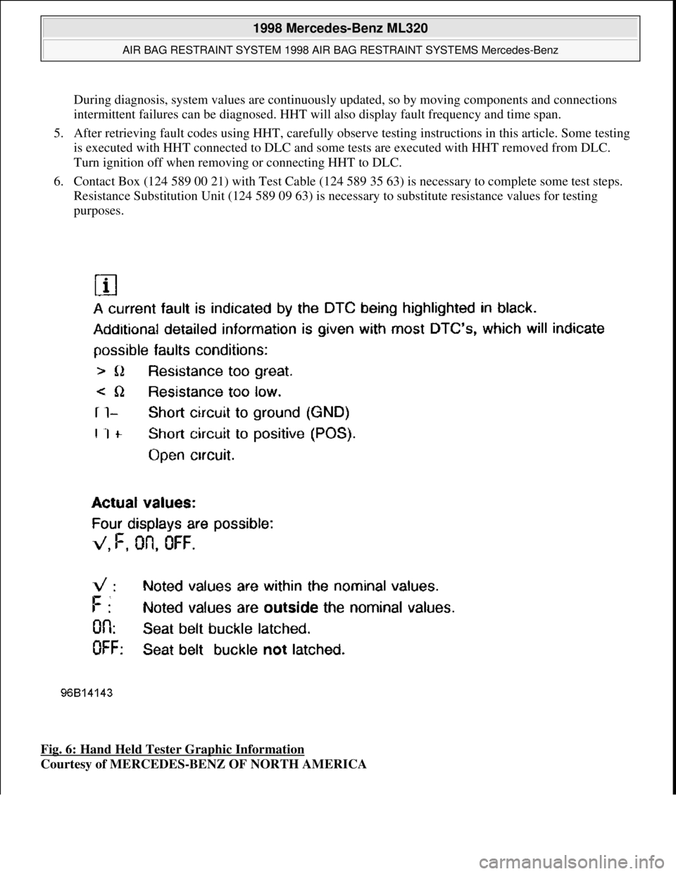
3. HHT will display a 3 digit fault code, and may display additional graphic information. This additional
graphic information will help in diagnosis of fault code. See Fig. 6
. During diagnosis HHT will display 4
different graphic displays informing technician if a test passes or fails, or if seat belt buckle is latched or
not latched. See Fig. 6
.
4. These
graphic displays are displayed as applicable by HHT during testing. See FAULT CODES table.
ApplicationFt. Lbs. (N.m)
Steering Wheel Hub Bolt52-66 (70-90)
INCH Lbs. (N.m)
Driver Air Bag Module Bolts (Torx)44-62 (5-7)
(1)Torque specifications are not available for clockspring assembly, control module or passenger-side
air bag module.
NOTE: After component replacement, perform a system operation check to ensure
proper system operation. See SYSTEM OPERATION CHECK
.
NOTE: Fault codes may only be retrieved using Hand-Held Tester (965 589 00 01) and
Adapter (965 589 00 40 or 965 589 00 50).
1998 Mercedes-Benz ML320
AIR BAG RESTRAINT SYSTEM 1998 AIR BAG RESTRAINT SYSTEMS Mercedes-Benz
me
Saturday, October 02, 2010 3:33:14 PMPage 16 © 2006 Mitchell Repair Information Company, LLC.
Page 17 of 4133
During diagnosis, system values are continuously updated, so by moving components and connections
intermittent failures can be diagnosed. HHT will also display fault frequency and time span.
5. After retrieving fault codes using HHT, carefully observe testing instructions in this article. Some testing
is executed with HHT connected to DLC and some tests are executed with HHT removed from DLC.
Turn ignition off when removing or connecting HHT to DLC.
6. Contact Box (124 589 00 21) with Test Cable (124 589 35 63) is necessary to complete some test steps.
Resistance Substitution Unit (124 589 09 63) is necessary to substitute resistance values for testing
purposes.
Fig. 6: Hand Held Tester Graphic Information
Courtesy of MERCEDES-BENZ OF NORTH AMERICA
1998 Mercedes-Benz ML320
AIR BAG RESTRAINT SYSTEM 1998 AIR BAG RESTRAINT SYSTEMS Mercedes-Benz
me
Saturday, October 02, 2010 3:33:14 PMPage 17 © 2006 Mitchell Repair Information Company, LLC.
Page 19 of 4133
CLEARING FAULT CODES
Connect Hand-Held Tester (965 589 00 01) to Data Link Connector (DLC). DLC is located in right rear corner
of engine compartment. It may be necessary to use Adapter (965 589 00 40 or 965 589 00 50) to connect HHT
to DLC. After HHT displays module number and version, press return key to start sequence. Using HHT,
follow HHT prompts to clear SRS fault codes. SRS codes are clear when ignition is turned on and SRS warning
light functions normally. See SYSTEM OPERATION CHECK
.
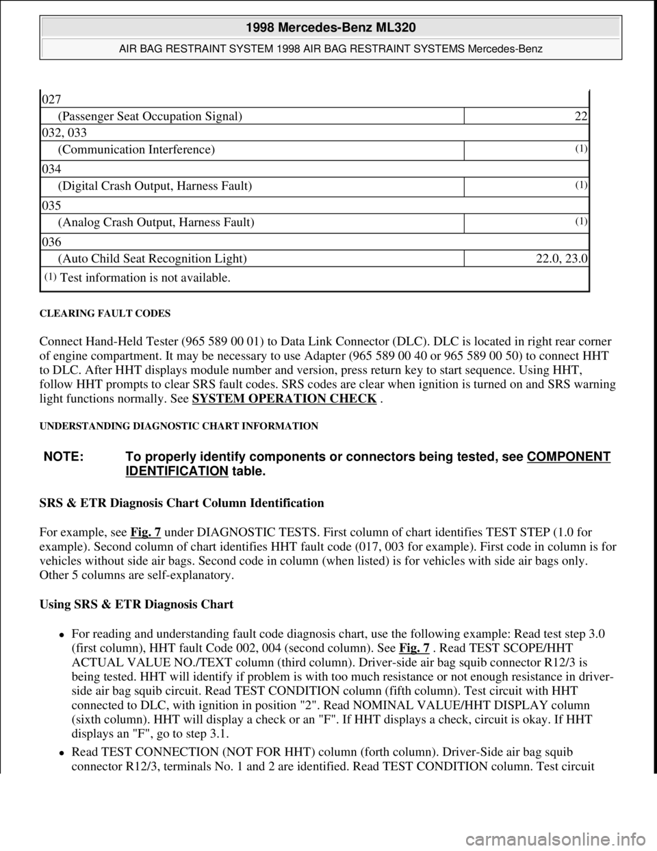
UNDERSTANDING DIAGNOSTIC CHART INFORMATION
SRS & ETR Diagnosis Chart Column Identification
For example, see Fig. 7
under DIAGNOSTIC TESTS. First column of chart identifies TEST STEP (1.0 for
example). Second column of chart identifies HHT fault code (017, 003 for example). First code in column is for
vehicles without side air bags. Second code in column (when listed) is for vehicles with side air bags only.
Other 5 columns are self-explanatory.
Using SRS & ETR Diagnosis Chart
For reading and understanding fault code diagnosis chart, use the following example: Read test step 3.0
(first column), HHT fault Code 002, 004 (second column). See Fig. 7
. Read TEST SCOPE/HHT
ACTUAL VALUE NO./TEXT column (third column). Driver-side air bag squib connector R12/3 is
being tested. HHT will identify if problem is with too much resistance or not enough resistance in driver-
side air bag squib circuit. Read TEST CONDITION column (fifth column). Test circuit with HHT
connected to DLC, with ignition in position "2". Read NOMINAL VALUE/HHT DISPLAY column
(sixth column). HHT will display a check or an "F". If HHT displays a check, circuit is okay. If HHT
displays an "F", go to step 3.1.
Read TEST CONNECTION (NOT FOR HHT) column (forth column). Driver-Side air bag squib
connector R12/3, terminals No. 1 and 2 are identified. Read TEST CONDITION column. Test circuit
027
(Passenger Seat Occupation Signal)22
032, 033
(Communication Interference)(1)
034
(Digital Crash Output, Harness Fault)(1)
035
(Analog Crash Output, Harness Fault)(1)
036
(Auto Child Seat Recognition Light)22.0, 23.0
(1)Test information is not available.
NOTE: To properly identify components or connectors being tested, see COMPONENT
IDENTIFICATION table.
1998 Mercedes-Benz ML320
AIR BAG RESTRAINT SYSTEM 1998 AIR BAG RESTRAINT SYSTEMS Mercedes-Benz
me
Saturday, October 02, 2010 3:33:14 PMPage 19 © 2006 Mitchell Repair Information Company, LLC.
Page 20 of 4133
with HHT connected to DLC and ignition key removed. Remove driver-side air bag module. Disconnect
driver-side air bag module squib connector R12/3. Connect Resistance Substitution Unit (124 589 09 63)
to driver-side air bag module squib connector (harness side). Set resistance substitution unit to 2 ohms.
Turn ignition key to position "2". Read NOMINAL VALUE/HHT DISPLAY column. If HHT displays a
check, replace driver-side air bag module. If HHT displays an "F", go to step 3.2.
Read TEST CONNECTION (NOT FOR HHT) column. Horn/air bag clockspring connector A45x1,
terminals No. 1 and 2 are identified. Read TEST CONDITION column. Test circuit with HHT connected
to DLC. Remove ignition key. Connect Resistance Substitution Unit (124 589 09 63 00) to horn/air bag
clockspring connector A45x1. Set resistance substitution unit to 2 ohms. Read NOMINAL VALUE/HHT
DISPLAY column. If HHT displays a check, check horn/air bag clockspring for continuity. Replace
horn/air bag clockspring as necessary. If HHT displays an "F", go to step 3.4.
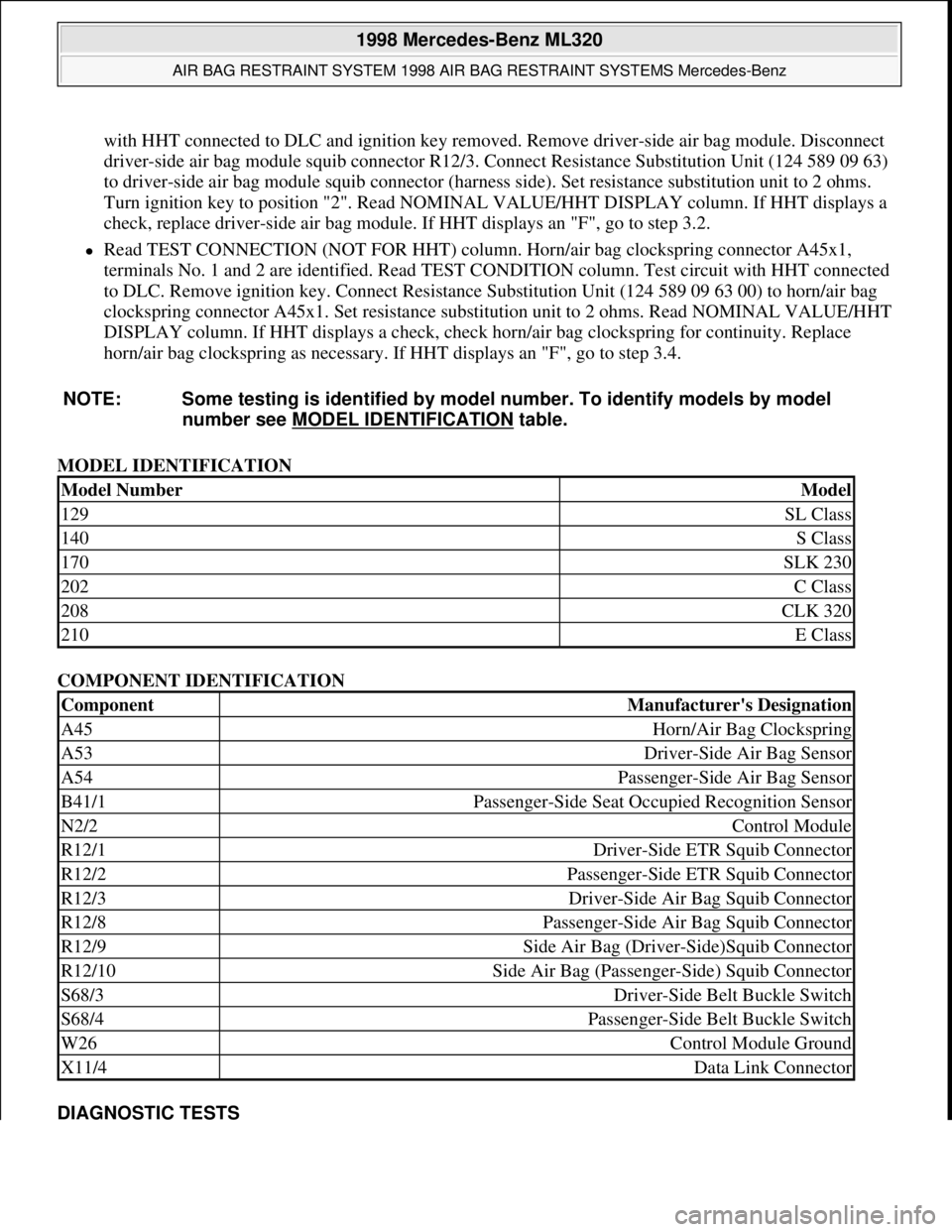
MODEL IDENTIFICATION
COMPONENT IDENTIFICATION
DIAGNOSTIC TESTS NOTE: Some testing is identified by model number. To identify models by model
number see MODEL IDENTIFICATION
table.
Model NumberModel
129SL Class
140S Class
170SLK 230
202C Class
208CLK 320
210E Class
ComponentManufacturer's Designation
A45Horn/Air Bag Clockspring
A53Driver-Side Air Bag Sensor
A54Passenger-Side Air Bag Sensor
B41/1Passenger-Side Seat Occupied Recognition Sensor
N2/2Control Module
R12/1Driver-Side ETR Squib Connector
R12/2Passenger-Side ETR Squib Connector
R12/3Driver-Side Air Bag Squib Connector
R12/8Passenger-Side Air Bag Squib Connector
R12/9Side Air Bag (Driver-Side)Squib Connector
R12/10Side Air Bag (Passenger-Side) Squib Connector
S68/3Driver-Side Belt Buckle Switch
S68/4Passenger-Side Belt Buckle Switch
W26Control Module Ground
X11/4Data Link Connector
1998 Mercedes-Benz ML320
AIR BAG RESTRAINT SYSTEM 1998 AIR BAG RESTRAINT SYSTEMS Mercedes-Benz
me
Saturday, October 02, 2010 3:33:14 PMPage 20 © 2006 Mitchell Repair Information Company, LLC.
Page 53 of 4133

3 ContentsSnow chains ................................ 179
Winter driving instructions ...... 180
Deep water .................................. 181
Passenger compartment ........... 182
Traveling abroad ........................ 182
Off-Road driving ............................. 183
Trailer towing ................................. 190
Cruise control ................................. 196
Brake assist system (BAS) ............ 199
Antilock brake system (ABS) ....... 201
Four-wheel electronic
traction system (4-ETS+) ..........203
Electronic brake
proportioning (EBP) ..................204
Electronic stability program
(ESP) ...........................................205
Transmission control –
LOW RANGE mode ...................209
What you should know
at the gas station ....................... 212
Check regularly and
before a long trip ....................... 215
Instrument cluster displayMalfunction and indicator
lamps in the
instrument cluster .....................218
On-board diagnostic system –
Check engine malfunction
indicator lamp .............................218
Brake warning lamp ...................219
Supplemental restraint system
(SRS) indicator lamp .................. 219
Fuel reserve warning ................ 220
Electronic stability
program (ESP) / Electronic
traction system (ETS) –
warning lamp ............................. 221
BAS/ESP malfunction
indicator lamp ............................ 221
4-ETS malfunction
indicator lamp ............................ 221
LOW RANGE
indicator lamp ............................ 221
ABS malfunction
indicator lamp ............................ 222Adjustable steering wheel –
indicator lamp .............................222
AIRBAG OFF
indicator lamp .............................222
Seat belt warning lamp .............223
Charge indicator lamp ...............223
Low engine oil level
warning lamp ..............................224
Low engine coolant
level warning ..............................224
Brake pad wear
indicator lamp .............................225
FSS indicator ...............................225
Page 64 of 4133
14 Introduction
Where to find it
The Operator’s Manual is divided into eight sections:
• Instruments and controls: An overview of all the controls that can be operated from the driver’s seat.
•Operation: Information on the vehicle’s equipment and its operation.
•Driving: Important information on driving.
• Instrument cluster display: Indicator lamps on the instrument cluster with brief instructions.
• Practical hints: Assistance and instructions in the event of an emergency.
•Car care: Instructions on caring for your vehicle.
• Technical data: All the important technical data for your vehicle as well as consumer information such as fuels,
coolants, lubricants etc. is contained here.
•Index: Key terms to help you find a topic quickly.
Other documents may also be supplied, depending on your vehicle’s equipment.
Explanation of color used:
Warning notices for the protection of yourself and
others appear on red background.
Page 67 of 4133
17 Contents - Instruments and controls
Te ch n ica l
data Instruments
and controlsOperation DrivingInstrument
cluster displayPractical hints Car care Index
Instruments and controlsInstruments and controls ............... 18
Center console .............................. 20
Overhead control panel ............... 21
Page 68 of 4133
18 Instruments and controls
Te ch n ica l
data Instruments
and controlsOperation DrivingInstrument
cluster displayPractical hints Car care Index
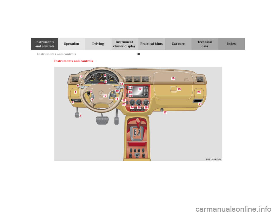
Instruments and controls