Page 16 of 4133

DIAGNOSIS & TESTING
Before proceeding,")
If any part of SRS wiring harness is damaged, DO NOT repair wiring harness, replace complete wiring harness.
TORQUE SPECIFICATIONS
TORQUE SPECIFICATIONS
(1)
DIAGNOSIS & TESTING
Before proceeding, see SERVICE PRECAUTIONS
. The control module is capable of diagnosing airbag
system components and ETR components. If a fault is detected by the control module or system is
malfunctioning, SRS warning light will do one or more of the following:
SRS warning light goes out after 2 minutes. System fault is noted, however occupant protection is not
affected. See RETRIEVING FAULT CODES
.
SRS warning light illuminates continuously. System is faulty which may result in a non deployment or
false deployment. See RETRIEVING FAULT CODES
.
SRS warning light blinks continuously. Control module has been replaced without setting control module
parameters.
RETRIEVING FAULT CODES
1. Check vehicle fuses. Replace any blown fuses as necessary. Ensure vehicle battery voltage is 11 volts or
more. Ensure SRS warning light functions. Turn ignition off. Connect Hand-Held Tester (HHT) (965 589
00 01) to Data Link Connector (DLC).
2. DLC is located in right rear corner of engine compartment. It may be necessary to use Adapter (965 589
00 40 or 965 589 00 50) to connect HHT to DLC. After HHT displays module number and version, press
return key to start diagnosis. Using HHT, follow HHT prompts to retrieve SRS fault codes.
3. HHT will display a 3 digit fault code, and may display additional graphic information. This additional
graphic information will help in diagnosis of fault code. See Fig. 6
. During diagnosis HHT will display 4
different graphic displays informing technician if a test passes or fails, or if seat belt buckle is latched or
not latched. See Fig. 6
.
4. These
graphic displays are displayed as applicable by HHT during testing. See FAULT CODES table.
ApplicationFt. Lbs. (N.m)
Steering Wheel Hub Bolt52-66 (70-90)
INCH Lbs. (N.m)
Driver Air Bag Module Bolts (Torx)44-62 (5-7)
(1)Torque specifications are not available for clockspring assembly, control module or passenger-side
air bag module.
NOTE: After component replacement, perform a system operation check to ensure
proper system operation. See SYSTEM OPERATION CHECK
.
NOTE: Fault codes may only be retrieved using Hand-Held Tester (965 589 00 01) and
Adapter (965 589 00 40 or 965 589 00 50).
1998 Mercedes-Benz ML320
AIR BAG RESTRAINT SYSTEM 1998 AIR BAG RESTRAINT SYSTEMS Mercedes-Benz
me
Saturday, October 02, 2010 3:33:14 PMPage 16 © 2006 Mitchell Repair Information Company, LLC.
Page 293 of 4133
243 Tires, Wheels
Te ch n ica l
data Instruments
and controlsOperation DrivingInstrument
cluster displayPractical hintsCar care Index Important!
To realize the total crumple zone in case of a rear end
collision, the space-saver spare wheel must be stored in
its holder with the tire deflated. Properly inflate the tire
prior to mounting it on the axle. See page 249 for
detailed instructions.
When storing the space-saver spare wheel in its holder,
tighten the three wheel bolts with a tightening torque of
37 ft.lb. (50 Nm).Space-saver tire (except ML 55 AMG)
Removing spare wheel (space-saver tire):
1. Hold left and right side of cover (1) at bottom and
pu ll aw ay fr o m b u mpe r ( arr ows ) .
P40.10-2368-26
Page 298 of 4133

248 Tires, Wheels
Te ch n ica l
data Instruments
and controlsOperation DrivingInstrument
cluster displayPractical hintsCar care Index
Using the wrench, tighten the five bolts evenly,
following the sequence illustrated, until all bolts are
tight. Observe a tightening torque of 110 ft.lb. (150 Nm).
Ensure proper tire pressure.Notes:
The removed road wheel cannot be stored in the
space-saver wheel carrier or inside the storage
compartment in the rear cargo area (ML 55 AMG), but
should be transported in the rear cargo compartment
wrapped in a protective cover supplied with the vehicle.
The protective cover is located in the rear cargo
compartment behind the cover in the right side trim
panel.
Model ML 55 AMG:
Store air pump in its proper location. Close and latch the
spare wheel cover, see page 239.
1
2
3
4
5
Wa r n i n g !
Always replace wheel bolts that are damaged or
rusted.Never apply oil or grease to wheel bolts.Damaged wheel hub threads should be repaired
immediately.Incorrect mounting bolts or improperly tightened
mounting bolts can cause the wheel to come off.
This could cause an accident. Be sure to use the
correct mounting bolts.
Page 432 of 4133
TORQUE SPECIFICATIONS
TORQUE SPECIFICATIONS
(1)
WIRING DIAGRAMS
ApplicationFt. Lbs (N.m)
Steering wheel hub bolt52-66 (70-90)
INCH Lbs. (N.m)
Driver air bag module bolts (torx)44-62 (5-7)
(1)Torque specifications are not av ailable for clockspring assembly, control module or passenger-side
air bag module.
2001 Mercedes-Benz ML320
2000-01 ACCESSORIES/SAFETY EQUIPMENT Merc edes-Benz - Air Bag Restraint Systems
me
Saturday, October 02, 2010 3:44:46 PMPage 68 © 2006 Mitchell Repair Information Company, LLC.
Page 710 of 4133
243
Tires, Wheels
Te ch n ica l
data
Instruments
and controls Operation Driving
Instrument
cluster display Practical hints
Car care Index
Important!
To realize the total crumple zone in case of a rear end
collision, the space-saver spare wheel must be stored in
its holder with the tire deflated. Properly inflate the tire
prior to mounting it on the axle. See page 249 for
detailed instructions.
When storing the space-saver spare wheel in its holder,
tighten the three wheel bolts with a tightening torque of
37 ft.lb. (50 Nm). Space-saver tire
(except ML 55 AMG)
Removing spare wheel (space-saver tire): 1. Hold left and right side of cover (1) at bottom and pu ll aw ay fr o m b u mpe r ( arr ows ) .
P40.10-2368-26
Page 715 of 4133

248
Tires, Wheels
Te ch n ica l
data
Instruments
and controls Operation Driving
Instrument
cluster display Practical hints
Car care Index
Using the wrench, tighten the five bolts evenly,
following the sequence illustrated, until all bolts are
tight. Observe a tightening torque of 110 ft.lb. (150 Nm).
Ensure proper tire pressure. Notes:
The removed road wheel cannot be stored in the
space-saver wheel carrier or inside the storage
compartment in the rear cargo area (ML 55 AMG), but
should be transported in the rear cargo compartment
wrapped in a protective cover supplied with the vehicle.
The protective cover is located in the rear cargo
compartment behind the cover in the right side trim
panel.
Model ML 55 AMG:
Store air pump in its proper location. Close and latch the
spare wheel cover, see page 239.
1
2
3
4
5
Wa r n i n g !
Always replace wheel bolts that are damaged or
rusted.Never apply oil or grease to wheel bolts.Damaged wheel hub threads should be repaired
immediately.Incorrect mounting bolts or improperly tightened
mounting bolts can cause the wheel to come off.
This could cause an accident. Be sure to use the
correct mounting bolts.
Page 1033 of 4133
229 Operation
Tires and wheels
Warning!
G
Have the tightening torque checked after
changing a wheel. Wheels could become
loose if not tightened with a torque of
110 lb-ft (150 Nm).
Use only genuine Mercedes-Benz wheel
bolts specified for your vehicle's rims.
Page 1081 of 4133
277 Practical hints
Flat tire
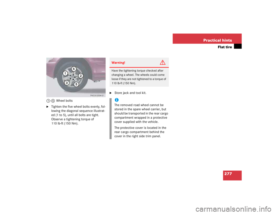
1-5Wheel bolts�
Tighten the five wheel bolts evenly, fol-
lowing the diagonal sequence illustrat-
ed (1 to 5), until all bolts are tight.
Observe a tightening torque of
110 lb-ft (150 Nm).
�
Store jack and tool kit.Warning!
G
Have the tightening torque checked after
changing a wheel. The wheels could come
loose if they are not tightened to a torque of
110 lb-ft (150 Nm).iThe removed road wheel cannot be
stored in the spare wheel carrier, but
should be transported in the rear cargo
compartment wrapped in a protective
cover supplied with the vehicle.
The protective cover is located in the
rear cargo compartment behind the
cover in the right side trim panel.


WIRING DIAGRAMS
ApplicationFt. Lbs (N.m)
Steering wheel hub bolt52-66 (70-90)
INCH Lbs. (N.m)
Driver air bag module bolts (torx)44-62 (5-7)
(1)T")

.
Use only genuine")