1997 MERCEDES-BENZ ML500 check engine
[x] Cancel search: check enginePage 16 of 4133
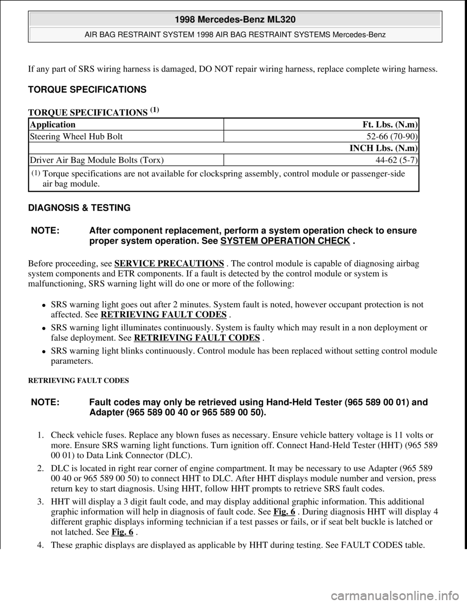
If any part of SRS wiring harness is damaged, DO NOT repair wiring harness, replace complete wiring harness.
TORQUE SPECIFICATIONS
TORQUE SPECIFICATIONS
(1)
DIAGNOSIS & TESTING
Before proceeding, see SERVICE PRECAUTIONS
. The control module is capable of diagnosing airbag
system components and ETR components. If a fault is detected by the control module or system is
malfunctioning, SRS warning light will do one or more of the following:
SRS warning light goes out after 2 minutes. System fault is noted, however occupant protection is not
affected. See RETRIEVING FAULT CODES
.
SRS warning light illuminates continuously. System is faulty which may result in a non deployment or
false deployment. See RETRIEVING FAULT CODES
.
SRS warning light blinks continuously. Control module has been replaced without setting control module
parameters.
RETRIEVING FAULT CODES
1. Check vehicle fuses. Replace any blown fuses as necessary. Ensure vehicle battery voltage is 11 volts or
more. Ensure SRS warning light functions. Turn ignition off. Connect Hand-Held Tester (HHT) (965 589
00 01) to Data Link Connector (DLC).
2. DLC is located in right rear corner of engine compartment. It may be necessary to use Adapter (965 589
00 40 or 965 589 00 50) to connect HHT to DLC. After HHT displays module number and version, press
return key to start diagnosis. Using HHT, follow HHT prompts to retrieve SRS fault codes.
3. HHT will display a 3 digit fault code, and may display additional graphic information. This additional
graphic information will help in diagnosis of fault code. See Fig. 6
. During diagnosis HHT will display 4
different graphic displays informing technician if a test passes or fails, or if seat belt buckle is latched or
not latched. See Fig. 6
.
4. These
graphic displays are displayed as applicable by HHT during testing. See FAULT CODES table.
ApplicationFt. Lbs. (N.m)
Steering Wheel Hub Bolt52-66 (70-90)
INCH Lbs. (N.m)
Driver Air Bag Module Bolts (Torx)44-62 (5-7)
(1)Torque specifications are not available for clockspring assembly, control module or passenger-side
air bag module.
NOTE: After component replacement, perform a system operation check to ensure
proper system operation. See SYSTEM OPERATION CHECK
.
NOTE: Fault codes may only be retrieved using Hand-Held Tester (965 589 00 01) and
Adapter (965 589 00 40 or 965 589 00 50).
1998 Mercedes-Benz ML320
AIR BAG RESTRAINT SYSTEM 1998 AIR BAG RESTRAINT SYSTEMS Mercedes-Benz
me
Saturday, October 02, 2010 3:33:14 PMPage 16 © 2006 Mitchell Repair Information Company, LLC.
Page 19 of 4133
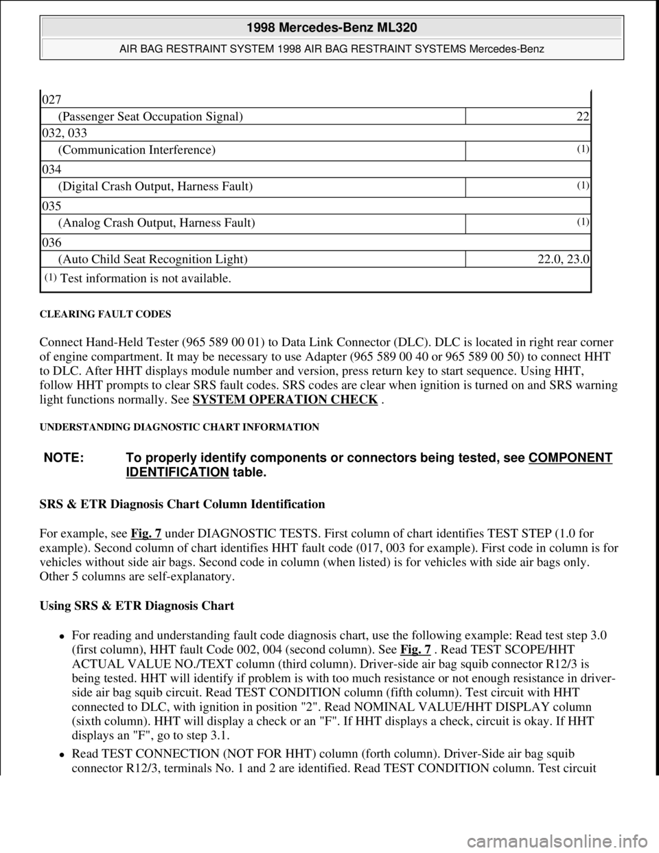
CLEARING FAULT CODES
Connect Hand-Held Tester (965 589 00 01) to Data Link Connector (DLC). DLC is located in right rear corner
of engine compartment. It may be necessary to use Adapter (965 589 00 40 or 965 589 00 50) to connect HHT
to DLC. After HHT displays module number and version, press return key to start sequence. Using HHT,
follow HHT prompts to clear SRS fault codes. SRS codes are clear when ignition is turned on and SRS warning
light functions normally. See SYSTEM OPERATION CHECK
.
UNDERSTANDING DIAGNOSTIC CHART INFORMATION
SRS & ETR Diagnosis Chart Column Identification
For example, see Fig. 7
under DIAGNOSTIC TESTS. First column of chart identifies TEST STEP (1.0 for
example). Second column of chart identifies HHT fault code (017, 003 for example). First code in column is for
vehicles without side air bags. Second code in column (when listed) is for vehicles with side air bags only.
Other 5 columns are self-explanatory.
Using SRS & ETR Diagnosis Chart
For reading and understanding fault code diagnosis chart, use the following example: Read test step 3.0
(first column), HHT fault Code 002, 004 (second column). See Fig. 7
. Read TEST SCOPE/HHT
ACTUAL VALUE NO./TEXT column (third column). Driver-side air bag squib connector R12/3 is
being tested. HHT will identify if problem is with too much resistance or not enough resistance in driver-
side air bag squib circuit. Read TEST CONDITION column (fifth column). Test circuit with HHT
connected to DLC, with ignition in position "2". Read NOMINAL VALUE/HHT DISPLAY column
(sixth column). HHT will display a check or an "F". If HHT displays a check, circuit is okay. If HHT
displays an "F", go to step 3.1.
Read TEST CONNECTION (NOT FOR HHT) column (forth column). Driver-Side air bag squib
connector R12/3, terminals No. 1 and 2 are identified. Read TEST CONDITION column. Test circuit
027
(Passenger Seat Occupation Signal)22
032, 033
(Communication Interference)(1)
034
(Digital Crash Output, Harness Fault)(1)
035
(Analog Crash Output, Harness Fault)(1)
036
(Auto Child Seat Recognition Light)22.0, 23.0
(1)Test information is not available.
NOTE: To properly identify components or connectors being tested, see COMPONENT
IDENTIFICATION table.
1998 Mercedes-Benz ML320
AIR BAG RESTRAINT SYSTEM 1998 AIR BAG RESTRAINT SYSTEMS Mercedes-Benz
me
Saturday, October 02, 2010 3:33:14 PMPage 19 © 2006 Mitchell Repair Information Company, LLC.
Page 53 of 4133

3 ContentsSnow chains ................................ 179
Winter driving instructions ...... 180
Deep water .................................. 181
Passenger compartment ........... 182
Traveling abroad ........................ 182
Off-Road driving ............................. 183
Trailer towing ................................. 190
Cruise control ................................. 196
Brake assist system (BAS) ............ 199
Antilock brake system (ABS) ....... 201
Four-wheel electronic
traction system (4-ETS+) ..........203
Electronic brake
proportioning (EBP) ..................204
Electronic stability program
(ESP) ...........................................205
Transmission control –
LOW RANGE mode ...................209
What you should know
at the gas station ....................... 212
Check regularly and
before a long trip ....................... 215
Instrument cluster displayMalfunction and indicator
lamps in the
instrument cluster .....................218
On-board diagnostic system –
Check engine malfunction
indicator lamp .............................218
Brake warning lamp ...................219
Supplemental restraint system
(SRS) indicator lamp .................. 219
Fuel reserve warning ................ 220
Electronic stability
program (ESP) / Electronic
traction system (ETS) –
warning lamp ............................. 221
BAS/ESP malfunction
indicator lamp ............................ 221
4-ETS malfunction
indicator lamp ............................ 221
LOW RANGE
indicator lamp ............................ 221
ABS malfunction
indicator lamp ............................ 222Adjustable steering wheel –
indicator lamp .............................222
AIRBAG OFF
indicator lamp .............................222
Seat belt warning lamp .............223
Charge indicator lamp ...............223
Low engine oil level
warning lamp ..............................224
Low engine coolant
level warning ..............................224
Brake pad wear
indicator lamp .............................225
FSS indicator ...............................225
Page 54 of 4133

4 Contents
Practical hintsFirst aid kit .....................................228
Fuses ................................................228
Electrical outlet ..............................230
Stowing things in the vehicle ......230
Hood ................................................. 231
Checking engine oil level .............233
Automatic transmission
fluid level ...................................234
Engine oil consumption ................234
Coolant level ...................................234
Adding coolant ...........................235
Windshield washer/headlamp
cleaning system .........................236
Windshield and
headlamp washer fluid
mixing ratio ................................237Vehicle jack, wheel bolt
wrench and screwdriver ......... 237
Air pump ......................................... 239
Wheels ............................................ 240
Tire replacement ....................... 240
Rotating wheels ......................... 241
Spare wheel .................................... 242
Changing wheels ........................... 245
Tire inflation pressure ................. 250
Battery ............................................. 251
Jump starting ................................. 253
Towing the vehicle ........................ 255
Transmission selector lever,
manually unlocking .................. 259
Stranded vehicle ............................ 259Exterior lamps ................................260
Headlamp assembly ................... 261
Taillamp assemblies ..................265
Adjusting headlamp aim ...............268
Remote control
battery replacement .................270
Synchronizing
remote control ............................ 271
Emergency operation of
sliding/pop-up roof ...................272
Emergency operation of
Skyview Top ...............................273
Manual release for
fuel filler flap ............................. 274
Replacing wiper blades .................275
Roof rack ......................................... 276
Page 123 of 4133
73 Rear view mirrors
Te ch n ica l
data Instruments
and controlsOperationDrivingInstrument
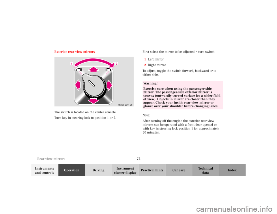
cluster displayPractical hints Car care Index Exterior rear view mirrors
The switch is located on the center console.
Turn key in steering lock to position 1 or 2.First select the mirror to be adjusted – turn switch:
1Left mirror
2Right mirror
To adjust, toggle the switch forward, backward or to
either side.
Note:
After turning off the engine the exterior rear view
mirrors can be operated with a front door opened or
with key in steering lock position 1 for approximately
30 minutes.
P82.00-2044-26
Wa r n i n g !
Exercise care when using the passenger-side
mirror. The passenger-side exterior mirror is
convex (outwardly curved surface for a wider field
of view). Objects in mirror are closer than they
appear. Check your inside rear view mirror or
glance over your shoulder before changing lanes.
Page 129 of 4133
79 Instrument cluster
Te ch n ica l
data Instruments
and controlsOperationDrivingInstrument
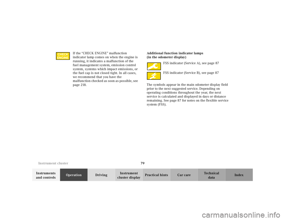
cluster displayPractical hints Car care Index If the “CHECK ENGINE” malfunction
indicator lamp comes on when the engine is
running, it indicates a malfunction of the
fuel management system, emission control
system, systems which impact emissions, or
the fuel cap is not closed tight. In all cases,
we recommend that you have the
malfunction checked as soon as possible, see
page 218.Additional function indicator lamps
(in the odometer display)
FSS indicator (Service A), see page 87
FSS indicator (Service B), see page 87
The symbols appear in the main odometer display field
prior to the next suggested service. Depending on
operating conditions throughout the year, the next
service is calculated and displayed in days or distance
remaining. See page 87 for notes on the flexible service
system (FSS).
CHECK
ENGINE
Page 139 of 4133
89 Engine oil level indicator
Te ch n ica l
data Instruments
and controlsOperationDrivingInstrument
cluster displayPractical hints Car care Index Engine oil level indicator
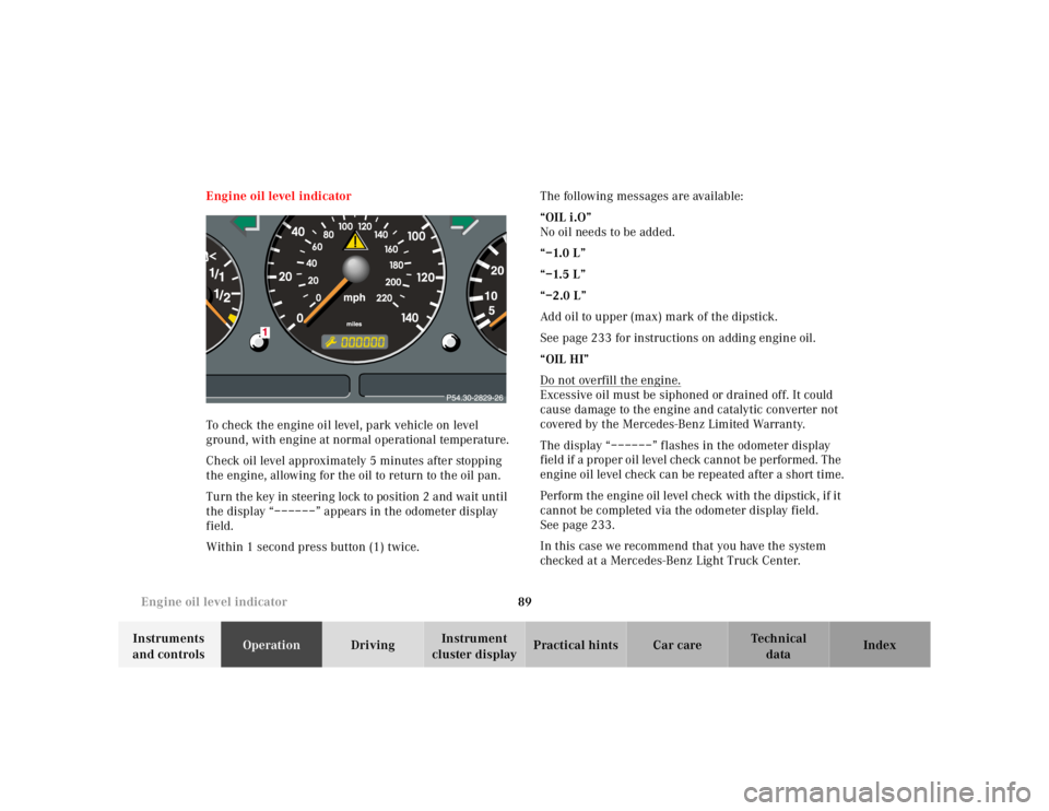
To check the engine oil level, park vehicle on level
ground, with engine at normal operational temperature.
Check oil level approximately 5 minutes after stopping
the engine, allowing for the oil to return to the oil pan.
Turn the key in steering lock to position 2 and wait until
the display “––––––” appears in the odometer display
field.
Within 1 second press button (1) twice.The following messages are available:
“OIL i.O”
No oil needs to be added.
“–1.0 L”
“–1.5 L”
“–2.0 L”
Add oil to upper (max) mark of the dipstick.
See page 233 for instructions on adding engine oil.
“OIL HI”
Do not overfill the engine.
Excessive oil must be siphoned or drained off. It could
cause damage to the engine and catalytic converter not
covered by the Mercedes-Benz Limited Warranty.
The display “––––––” flashes in the odometer display
field if a proper oil level check cannot be performed. The
engine oil level check can be repeated after a short time.
Perform the engine oil level check with the dipstick, if it
cannot be completed via the odometer display field.
See page 233.
In this case we recommend that you have the system
checked at a Mercedes-Benz Light Truck Center.
Page 195 of 4133
145 Contents - Driving
Te ch n ica l
data Instruments
and controlsOperationDrivingInstrument
cluster displayPractical hints Car care Index
DrivingControl and operation of
radio transmitters ..................... 146
The first 1 000 miles
(1 500 km) ................................. 147
Maintenance ................................... 147
Tele Aid ........................................... 148
Catalytic converter ........................ 160
Emission control ............................ 161
Steering lock ................................... 162
Starting and turning off
the engine .................................. 164
Automatic transmission ............... 165
Parking brake ................................. 173Driving instructions .......................174
Drive sensibly – save fuel .........174
Drinking and driving .................174
Pedals ...........................................174
Power assistance ........................ 175
Brakes .......................................... 175
Driving off .................................... 176
Parking ......................................... 176
Tires ............................................. 177
Snow chains ............................... 179
Winter driving instructions ......180
Deep water ...................................181
Passenger compartment ............182
Traveling abroad .........................182Off-Road driving ............................. 183
Trailer towing ................................. 190
Cruise control ................................. 196
Brake assist system (BAS) ............ 199
Antilock brake system (ABS) ....... 201
Four-wheel electronic
traction system (4-ETS+) ..........203
Electronic brake
proportioning (EBP) ..................204
Electronic stability program
(ESP) ...........................................205
Transmission control –
LOW RANGE mode ...................209
What you should know
at the gas station ....................... 212
Check regularly and
before a long trip ...................... 215