1997 MERCEDES-BENZ ML500 timing belt
[x] Cancel search: timing beltPage 2088 of 4133

16
Remove poly V-belt (8)
Installation:
Lock tensioning device with
a drift or pin (diameter 5 mm).
Model 163.154 /157 /172.
AR13.22-P-1202B
Model 163.174 /175.
AR13.22-P-1202BA
17
Detach the coolant line (16) at the cylinder
head on the left
6 mm socket hexagon
*WH58.30-Z-1001-06A
7 mm socket hexagon
*WH58.30-Z-1002-06A
18.1
Remove fender liner (9)
Only with engine 113.113.942 /965 / 981.
AR88.10-P-1300GH
19.1
Remove shield (10)
Only with engine 113.942 /965 /981.
20.1
Remove exhaust bracket (11)
Only with engine 113.942 /965 /981.
Support exhaust system.
21
Detach exhaust system at exhaust manifold
Installation:
On vehicles with engine
damage, the exhaust system must be
examined for swarfs before assembling and
any swarfs present must be removed, in order
to avoid consequential damage.
*BA14.10-P-1002-01B
22
Position crankshaft to 40° after ignition TDC
on cylinder 1
The engine must not be turned back;
otherwise the timing chain can get jammed.
AR05.10-P-6858V
Rotate engine at the crankshaft in running
direction until scribe mark 40° on pulley/
vibration damper corresponds with scribe
mark on timing case.
The grooves on the camshafts must be
pointing toward the inner V.
23
Lock camshafts with locating plates
Locating plate
*112589003200
Locating plate
*112589013200
24
Remove chain tensioner (17)
Model 163.154 /157 with engine 112.942/
970, model 163.172 with engine 113.942.
AR05.10-P-7800C
Model 163.174 /175 with engine 113.981/ 965.
AR05.10-P-7800CA
25.1
Remove oil filter housing (18) together with oil-
water heat exchanger
Engine 113.942.
AR18.20-P-3471B
Engine 112.942/970.
AR18.20-P-3471BA
26
Unscrew camshaft sprockets (19)
If camshaft sprockets are removed,
engine must no longer be cranked, otherwise
timing chain might jam.
Engine 113.942 /965 /981:
#
Tie timing chain tight on both camshaft
sprockets with tie straps.
Engine 112.942 /970:
#
Right-hand camshaft sprocket:
Tie timing chain tight on camshaft sprocket
with tie strap.
Left-hand camshaft sprocket:
Mark camshaft sprocket to timing chain and
remove camshaft sprocket.
It is not possible for the timing chain to
jump across at the crankshaft and balancing
shaft.
After installation:
#
Inspect basic position of camshafts.
AR05.10-P-6858V
If necessary after checking:
#
Set the basic position of camshafts
AR05.20-P-6020AU
Open-end wrench
*112589000100
Insertion tool
*112589010300
Torque wrench
*001589722100
*BA05.20-P-1001-01B
27
Remove camshaft bearing bridges (28)
Pay attention to slackening and tightening
pattern!
AR05.20-P-7103AU
28
Unscrew bolts, cylinder head
!
timing case
cover (20)
*BA01.40-P-1002-01C
Copyright DaimlerChrysler AG 20.05.2006 CD-Ausgabe G/10/04 . This WIS print-out will not be recorde
d by Modification services.
Page 4
Page 2096 of 4133

16
Remove poly V-belt (8)
Installation:
Lock tensioning device with
a drift or pin (diameter 5 mm).
Model 163.154 /157 /172.
AR13.22-P-1202B
Model 163.174 /175.
AR13.22-P-1202BA
17
Detach the coolant line (16) at the cylinder
head on the left
6 mm socket hexagon
*WH58.30-Z-1001-06A
7 mm socket hexagon
*WH58.30-Z-1002-06A
18.1
Remove fender liner (9)
Only with engine 113.113.942 /965 / 981.
AR88.10-P-1300GH
19.1
Remove shield (10)
Only with engine 113.942 /965 /981.
20.1
Remove exhaust bracket (11)
Only with engine 113.942 /965 /981.
Support exhaust system.
21
Detach exhaust system at exhaust manifold
Installation:
On vehicles with engine
damage, the exhaust system must be
examined for swarfs before assembling and
any swarfs present must be removed, in order
to avoid consequential damage.
*BA14.10-P-1002-01B
22
Position crankshaft to 40° after ignition TDC
on cylinder 1
The engine must not be turned back;
otherwise the timing chain can get jammed.
AR05.10-P-6858V
Rotate engine at the crankshaft in running
direction until scribe mark 40° on pulley/
vibration damper corresponds with scribe
mark on timing case.
The grooves on the camshafts must be
pointing toward the inner V.
23
Lock camshafts with locating plates
Locating plate
*112589003200
Locating plate
*112589013200
24
Remove chain tensioner (17)
Model 163.154 /157 with engine 112.942/
970, model 163.172 with engine 113.942.
AR05.10-P-7800C
Model 163.174 /175 with engine 113.981/ 965.
AR05.10-P-7800CA
25.1
Remove oil filter housing (18) together with oil-
water heat exchanger
Engine 113.942.
AR18.20-P-3471B
Engine 112.942/970.
AR18.20-P-3471BA
26
Unscrew camshaft sprockets (19)
If camshaft sprockets are removed,
engine must no longer be cranked, otherwise
timing chain might jam.
Engine 113.942 /965 /981:
#
Tie timing chain tight on both camshaft
sprockets with tie straps.
Engine 112.942 /970:
#
Right-hand camshaft sprocket:
Tie timing chain tight on camshaft sprocket
with tie strap.
Left-hand camshaft sprocket:
Mark camshaft sprocket to timing chain and
remove camshaft sprocket.
It is not possible for the timing chain to
jump across at the crankshaft and balancing
shaft.
After installation:
#
Inspect basic position of camshafts.
AR05.10-P-6858V
If necessary after checking:
#
Set the basic position of camshafts
AR05.20-P-6020AU
Open-end wrench
*112589000100
Insertion tool
*112589010300
Torque wrench
*001589722100
*BA05.20-P-1001-01B
27
Remove camshaft bearing bridges (28)
Pay attention to slackening and tightening
pattern!
AR05.20-P-7103AU
28
Unscrew bolts, cylinder head
!
timing case
cover (20)
*BA01.40-P-1002-01C
Copyright DaimlerChrysler AG 20.05.2006 CD-Ausgabe G/10/04 . This WIS print-out will not be recorde
d by Modification services.
Page 4
Page 2145 of 4133
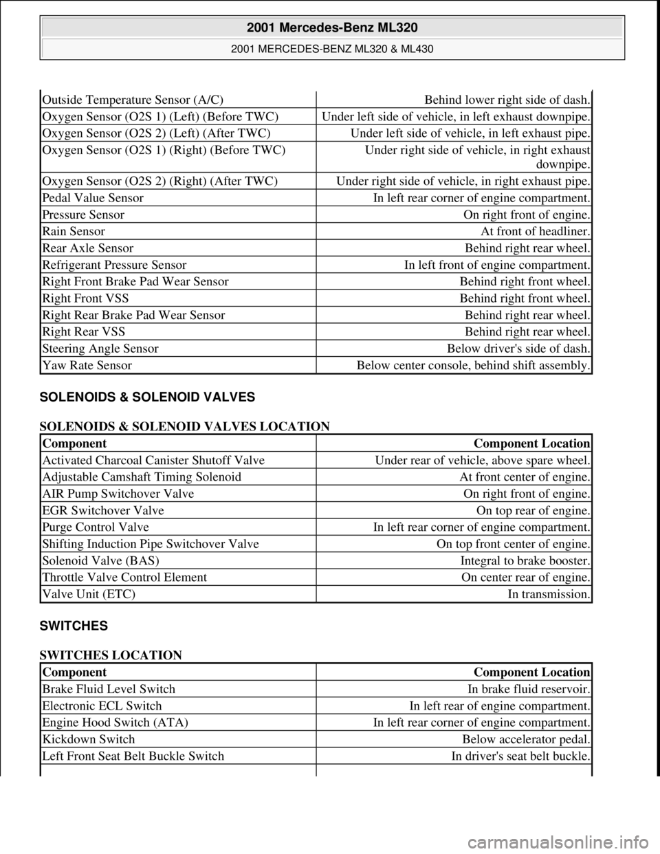
SOLENOIDS & SOLENOID VALVES
SOLENOIDS & SOLENOID VALVES LOCATION
SWITCHES
SWITCHES LOCATION
Outside Temperature Sensor (A/C)Behind lower right side of dash.
Oxygen Sensor (O2S 1) (Left) (Before TWC)Under left side of vehicle, in left exhaust downpipe.
Oxygen Sensor (O2S 2) (Left) (After TWC)Under left side of vehicle, in left exhaust pipe.
Oxygen Sensor (O2S 1) (Right) (Before TWC)Under right side of vehicle, in right exhaust
downpipe.
Oxygen Sensor (O2S 2) (Right) (After TWC)Under right side of vehicle, in right exhaust pipe.
Pedal Value SensorIn left rear corner of engine compartment.
Pressure SensorOn right front of engine.
Rain SensorAt front of headliner.
Rear Axle SensorBehind right rear wheel.
Refrigerant Pressure SensorIn left front of engine compartment.
Right Front Brake Pad Wear SensorBehind right front wheel.
Right Front VSSBehind right front wheel.
Right Rear Brake Pad Wear SensorBehind right rear wheel.
Right Rear VSSBehind right rear wheel.
Steering Angle SensorBelow driver's side of dash.
Yaw Rate SensorBelow center console, behind shift assembly.
ComponentComponent Location
Activated Charcoal Canister Shutoff ValveUnder rear of vehicle, above spare wheel.
Adjustable Camshaft Timing SolenoidAt front center of engine.
AIR Pump Switchover ValveOn right front of engine.
EGR Switchover ValveOn top rear of engine.
Purge Control ValveIn left rear corner of engine compartment.
Shifting Induction Pipe Switchover ValveOn top front center of engine.
Solenoid Valve (BAS)Integral to brake booster.
Throttle Valve Control ElementOn center rear of engine.
Valve Unit (ETC)In transmission.
ComponentComponent Location
Brake Fluid Level SwitchIn brake fluid reservoir.
Electronic ECL SwitchIn left rear of engine compartment.
Engine Hood Switch (ATA)In left rear corner of engine compartment.
Kickdown SwitchBelow accelerator pedal.
Left Front Seat Belt Buckle SwitchIn driver's seat belt buckle.
2001 Mercedes-Benz ML320
2001 MERCEDES-BENZ ML320 & ML430
me
Saturday, October 02, 2010 3:21:17 PMPage 5 © 2006 Mitchell Repair Information Company, LLC.
Page 2254 of 4133
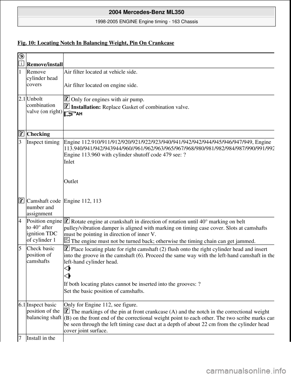
Fig. 10: Locating Notch In Balancing Weight, Pin On Crankcase
Remove/install
1Remove
cylinder head
covers Air filter located
at vehicle side.
Air filter located on engine side.
2.1Unbolt
combination
valve (on right) Only for engines with air pump.
Installation: Replace Gasket of combination valve.
Checking
3Inspect timing Engine 112.910/911/912/920/921/ 922/923/940/941/942/942/944/945/946/947/949, Engine
113.940/941/942/943944/960//961/962/963/965/ 967/968/980/981/982/984/987/990/991/99
2
Engine 113.960 with cylinder shutoff code 479 see: ?
Inlet
Outlet
Camshaft code
number and
assignmentEngine 112, 113
4Position engine
to 40° after
ignition TDC
of cylinder 1 Rotate engine at crankshaft in direct ion of rotation until 40° marking on belt
pulley/vibration damper is aligned with mark ing on timing case cover. Slots at camshafts
must be pointing in di rection of inner V.
The engine must not be turned back; otherwise the timing chain can get jammed.
5Check basic
position of
camshafts Place locating plate for right camshaft (2) fl
ush onto the right cylinder head and insert
into the groove in the camshaft (6). Proceed the same way with the left-hand camshaft in th
e
left-hand cylinder head.
If both locating plates cannot be inserted into the grooves: ?
Set the basic position of camshafts.
6.1Inspect basic
position of the
balancing shaftOnly for Engine 112, see figure.
The markings of the pin at front crankcase (A) and the notch in the correctional weight
(B) on the front end of the corr ectional weight point to each ot her. The two scribe marks ca
n
be seen through the left timing case duct at a depth of about 22 cm from the cylinder head
cover joint surface.
7Install in the
2004 Mercedes-Benz ML350
1998-2005 ENGINE Engine timing - 163 Chassis
me
Saturday, October 02, 2010 3:39:37 PMPage 13 © 2006 Mitchell Repair Information Company, LLC.
Page 2282 of 4133
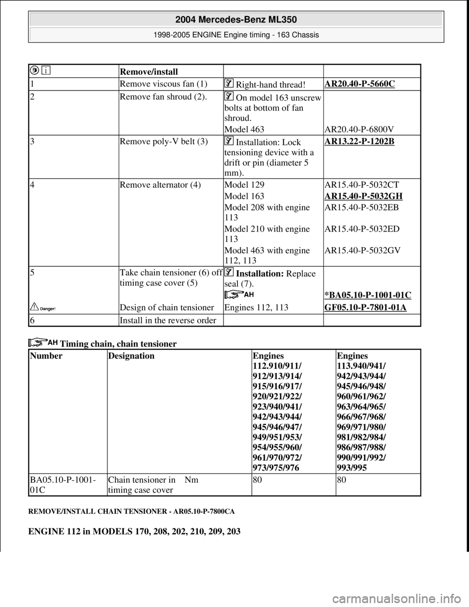
Timing chain, chain tensioner
REMOVE/INSTALL CHAIN TE NSIONER - AR05.10-P-7800CA
ENGINE 112 in MODELS 170, 208, 202, 210, 209, 203
Remove/install
1Remove viscous fan (1) Right-hand thread!AR20.40-P-5660C
2Remove fan shroud (2).On model 163 unscrew
bolts at bottom of fan
shroud.
Model 463AR20.40-P-6800V
3Remove poly-V belt (3) Installation: Lock
tensioning device with a
drift or pin (diameter 5
mm).AR13.22-P-1202B
4Remove alternator (4)Model 129AR15.40-P-5032CT
Model 163AR15.40-P-5032GH
Model 208 with engine
113AR15.40-P-5032EB
Model 210 with engine
113AR15.40-P-5032ED
Model 463 with engine
112, 113AR15.40-P-5032GV
5Take chain tensioner (6) off
timing case cover (5) Installation: Replace
seal (7).
*BA05.10-P-1001-01C
Design of chain tensionerEngines 112, 113GF05.10-P-7801-01A
6Install in the reverse order
NumberDesignationEngines
112.910/911/
912/913/914/
915/916/917/
920/921/922/
923/940/941/
942/943/944/
945/946/947/
949/951/953/
954/955/960/
961/970/972/
973/975/976Engines
113.940/941/
942/943/944/
945/946/948/
960/961/962/
963/964/965/
966/967/968/
969/971/980/
981/982/984/
986/987/988/
990/991/992/
993/995
BA05.10-P-1001-
01CChain tensioner in
timing case coverNm8080
2004 Mercedes-Benz ML350
1998-2005 ENGINE Engine timing - 163 Chassis
me
Saturday, October 02, 2010 3:39:38 PMPage 41 © 2006 Mitchell Repair Information Company, LLC.
Page 2305 of 4133
ENGINE 113.962 in MODELS 463.206 / 240 /241 /247 /248 /249 /254
ENGINE 113.982 in MODEL 463.243/246
ENGINE 113 in MODELS 129, 163, 202, 203, 208, 209, 210, 211, 215, 220, 230
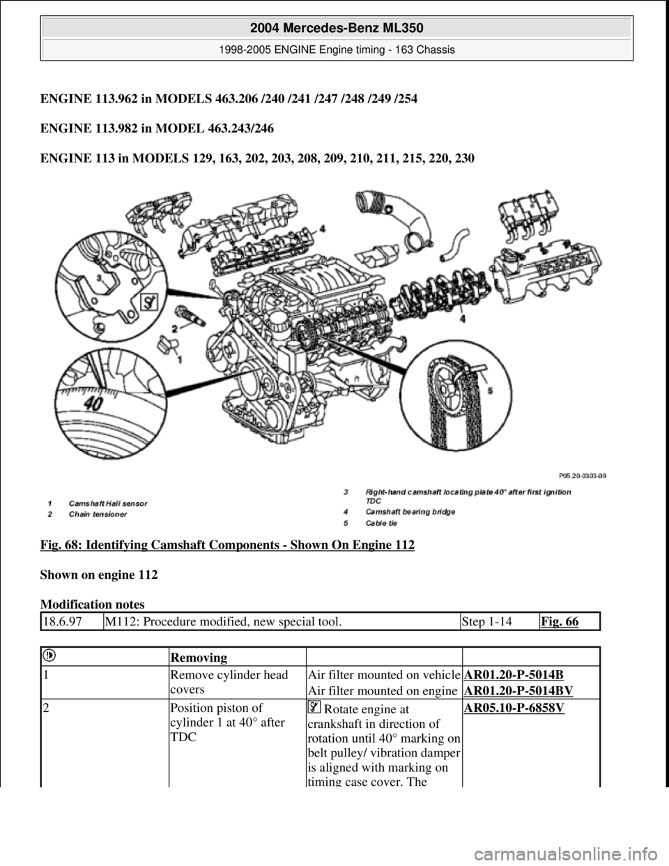
Fig. 68: Identifying Camshaft Components
- Shown On Engine 112
Shown on engine 112
Modification notes
18.6.97M112: Procedure modified, new special tool.Step 1-14Fig. 66
Removing
1Remove cylinder head
coversAir filter mount ed on vehicleAR01.20-P-5014B
Air filter mounted on engineAR01.20-P-5014BV
2Position piston of
cylinder 1 at 40° after
TDC Rotate engine at
crankshaft in direction of
rotation until 40° marking on
belt pulley/ vibration damper
is aligned with marking on
timing case cover. The
AR05.10-P-6858V
2004 Mercedes-Benz ML350
1998-2005 ENGINE Engine timing - 163 Chassis
me
Saturday, October 02, 2010 3:39:38 PMPage 64 © 2006 Mitchell Repair Information Company, LLC.
Page 2313 of 4133
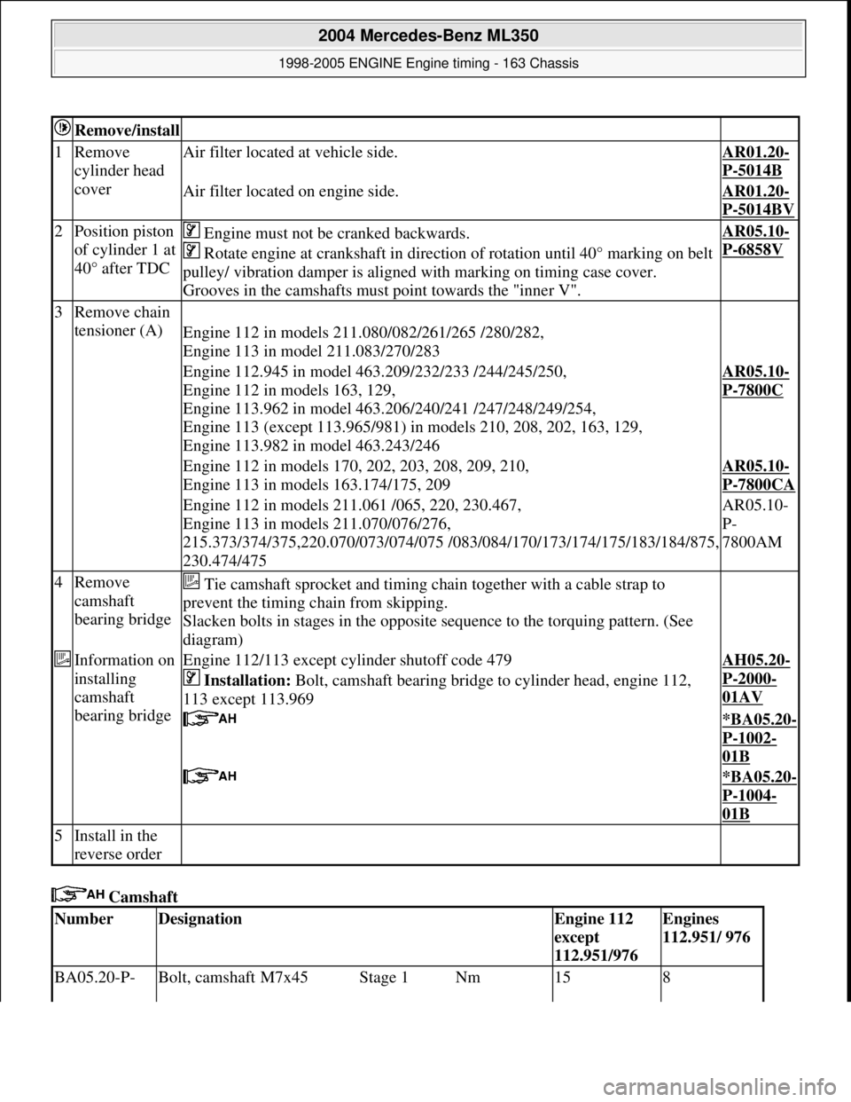
Camshaft
Remove/install
1Remove
cylinder head
coverAir filter located at vehicle side.AR01.20-
P-5014B
Air filter located on engine side.AR01.20-
P-5014BV
2Position piston
of cylinder 1 at
40° after TDC Engine must not be cranked backwards.
Rotate engine at crankshaft in direct ion of rotation until 40° marking on belt
pulley/ vibration damper is aligned with marking on timing case cover.
Grooves in the camshafts must point towards the "inner V".AR05.10-
P-6858V
3Remove chain
tensioner (A)
Engine 112 in models 211.080/082/261/265 /280/282,
Engine 113 in model 211.083/270/283
Engine 112.945 in model 463.209/232/233 /244/245/250,
Engine 112 in models 163, 129,
Engine 113.962 in model 463.206/240/241 /247/248/249/254,
Engine 113 (except 113.965/981) in models 210, 208, 202, 163, 129,
Engine 113.982 in model 463.243/246AR05.10-
P-7800C
Engine 112 in models 170, 202, 203, 208, 209, 210,
Engine 113 in models 163.174/175, 209AR05.10-
P-7800CA
Engine 112 in models 211.061 /065, 220, 230.467,
Engine 113 in models 211.070/076/276,
215.373/374/375,220.070/073/074/075 /083/ 084/170/173/174/175/183/184/875,
230.474/475AR05.10-
P-
7800AM
4Remove
camshaft
bearing bridge Tie camshaft sprocket and timing ch ain together with a cable strap to
prevent the timing chain from skipping.
Slacken bolts in stages in the opposite sequence to the torquing pattern. (See
diagram)
Information on
installing
camshaft
bearing bridgeEngine 112/113 except cylinder shutoff code 479
Installation: Bolt, camshaft bearing bridge to cylinder head, engine 112,
113 except 113.969AH05.20-
P-2000-
01AV
*BA05.20-
P-1002-
01B
*BA05.20-
P-1004-
01B
5Install in the
reverse order
NumberDesignationEngine 112
except
112.951/976Engines
112.951/ 976
BA05.20-P- Bolt, camshaft M7x45Stage 1Nm158
2004 Mercedes-Benz ML350
1998-2005 ENGINE Engine timing - 163 Chassis
me
Saturday, October 02, 2010 3:39:38 PMPage 72 © 2006 Mitchell Repair Information Company, LLC.
Page 2320 of 4133
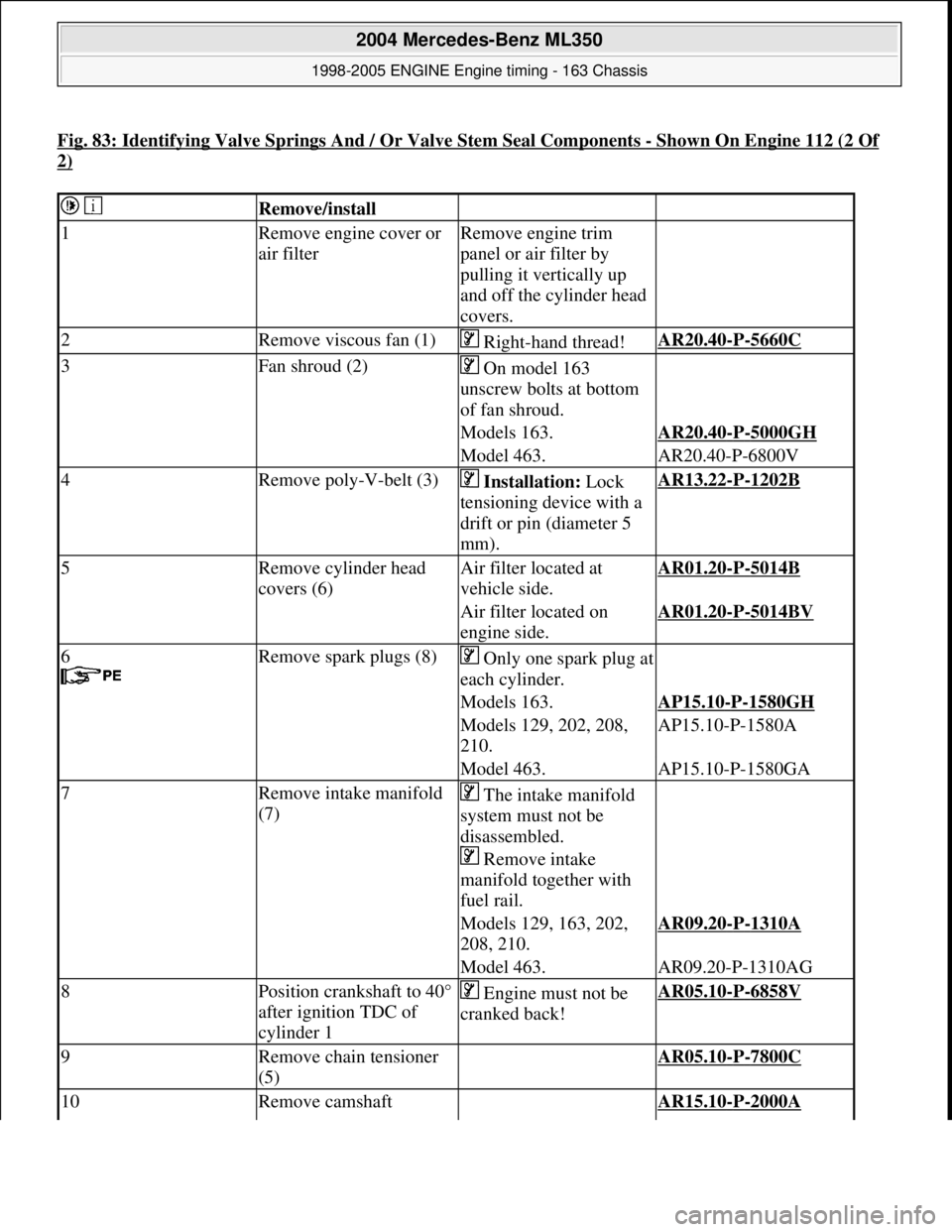
Fig. 83: Identifying Valve Springs And / Or Valve Stem Seal Components -Shown On Engine 112 (2 Of
2)
Remove/install
1Remove engine cover or
air filterRemove engine trim
panel or air filter by
pulling it vertically up
and off the cylinder head
covers.
2Remove viscous fan (1) Right-hand thread!AR20.40-P-5660C
3Fan shroud (2) On model 163
unscrew bolts at bottom
of fan shroud.
Models 163.AR20.40-P-5000GH
Model 463.AR20.40-P-6800V
4Remove poly-V-belt (3) Installation: Lock
tensioning device with a
drift or pin (diameter 5
mm).AR13.22-P-1202B
5Remove cylinder head
covers (6)Air filter located at
vehicle side.AR01.20-P-5014B
Air filter located on
engine side.AR01.20-P-5014BV
6
Remove spark plugs (8)Only one spark plug at
each cylinder.
Models 163.AP15.10-P-1580GH
Models 129, 202, 208,
210.AP15.10-P-1580A
Model 463.AP15.10-P-1580GA
7Remove intake manifold
(7) The intake manifold
system must not be
disassembled.
Remove intake
manifold together with
fuel rail.
Models 129, 163, 202,
208, 210.AR09.20-P-1310A
Model 463.AR09.20-P-1310AG
8Position crankshaft to 40°
after ignition TDC of
cylinder 1 Engine must not be
cranked back!AR05.10-P-6858V
9Remove chain tensioner
(5) AR05.10-P-7800C
10Remove camshaft AR15.10-P-2000A
2004 Mercedes-Benz ML350
1998-2005 ENGINE Engine timing - 163 Chassis
me
Saturday, October 02, 2010 3:39:38 PMPage 79 © 2006 Mitchell Repair Information Company, LLC.