Page 1982 of 4133
AR88.20-P-2200GH
Remove/install rear bumper
6.4.99
MODEL
163.113 #A up to 289564,
163.154 #X up to 754619,
163.154 #A up to 289564,
163.136 /172
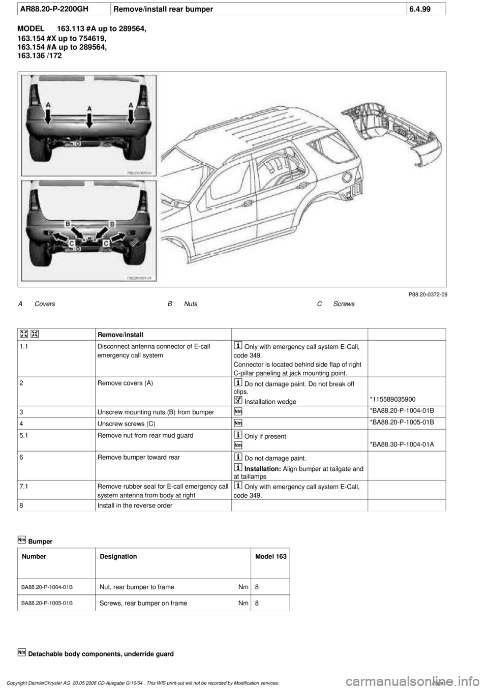
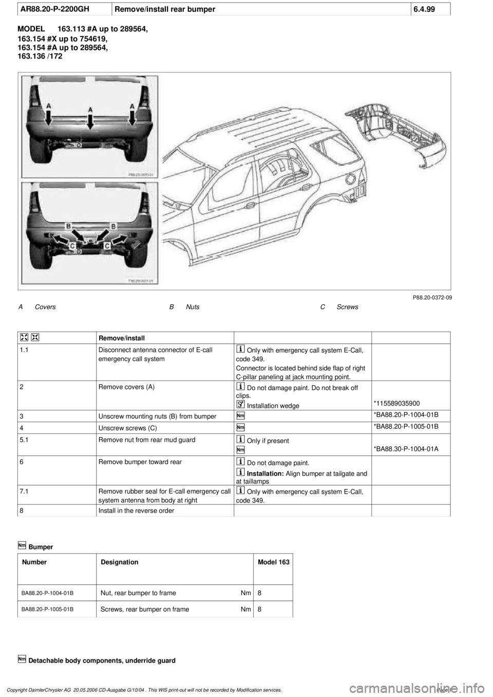
P88.20-0372-09
A
Covers
C
Screws
B
Nuts
Remove/install
1.1
Disconnect antenna connector of E-call
emergency call system
Only with emergency call system E-Call,
code 349.
Connector is located behind side flap of right
C-pillar paneling at jack mounting point.
2
Remove covers (A)
Do not damage paint. Do not break off
clips.
Installation wedge
*115589035900
3
Unscrew mounting nuts (B) from bumper
*BA88.20-P-1004-01B
4
Unscrew screws (C)
*BA88.20-P-1005-01B
5.1
Remove nut from rear mud guard
Only if present
*BA88.30-P-1004-01A
6
Remove bumper toward rear
Do not damage paint.
Installation:
Align bumper at tailgate and
at taillamps
7.1
Remove rubber seal for E-call emergency call
system antenna from body at right
Only with emergency call system E-Call,
code 349.
8
Install in the reverse order
Bumper
Number
Designation
Model 163
BA88.20-P-1004-01B
Nut, rear bumper to frame
Nm
8
BA88.20-P-1005-01BScrews, rear bumper on frame
Nm
8
Copyright DaimlerChrysler AG 20.05.2006 CD-Ausgabe G/10/04 . This WIS print-out will not be recorde
d by Modification services.
Page 1
Page 1989 of 4133
AR88.20-P-2000GI
Remove/install front bumper
5.4.99
MODEL
163.113 /128 /136 /154 /157 /172 /175 with CODE (U49) Styling package
MODEL
163.174
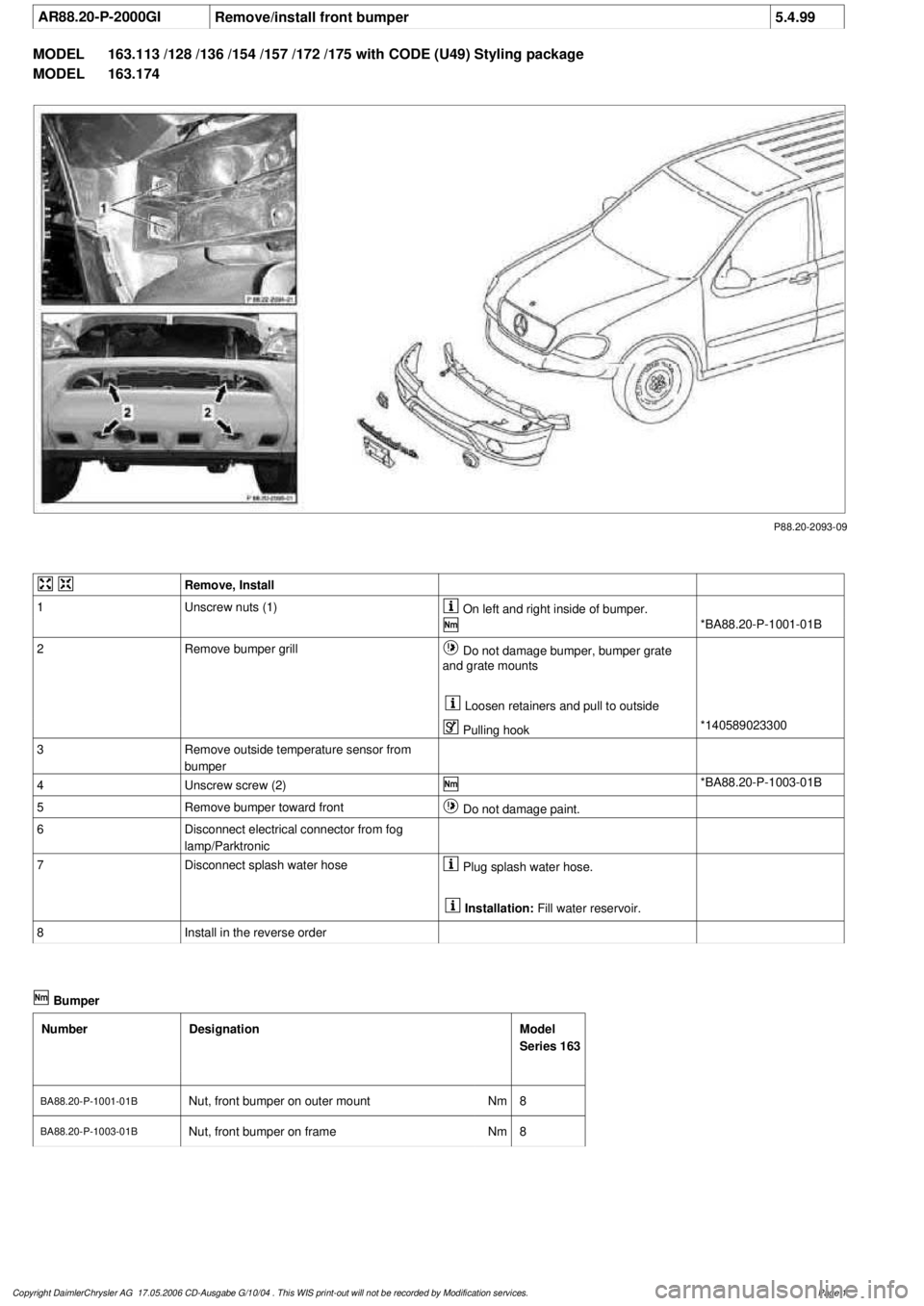
P88.20-2093-09
Remove, Install
1
Unscrew nuts (1)
On left and right inside of bumper.
*BA88.20-P-1001-01B
2
Remove bumper grill
Do not damage bumper, bumper grate
and grate mounts
Loosen retainers and pull to outside
Pulling hook
*140589023300
3
Remove outside temperature sensor from
bumper
4
Unscrew screw (2)
*BA88.20-P-1003-01B
5
Remove bumper toward front
Do not damage paint.
6
Disconnect electrical connector from fog
lamp/Parktronic
7
Disconnect splash water hose
Plug splash water hose.
Installation:
Fill water reservoir.
8
Install in the reverse order
Bumper
Number
Designation
Model
Series 163
BA88.20-P-1001-01B
Nut, front bumper on outer mount
Nm
8
BA88.20-P-1003-01B
Nut, front bumper on frame
Nm
8
Copyright DaimlerChrysler AG 17.05.2006 CD-Ausgabe G/10/04 . This WIS print-out will not be recorde
d by Modification services.
Page 1
Page 1994 of 4133
AR88.20-P-2000GH
Remove/install front bumper
14.3.97
MODEL
163.113 /154 #A up to 289564,
163.113 #X up to 754619,
163.154 #X up to 716524,
163.136 /172 except CODE (U49) Styling package
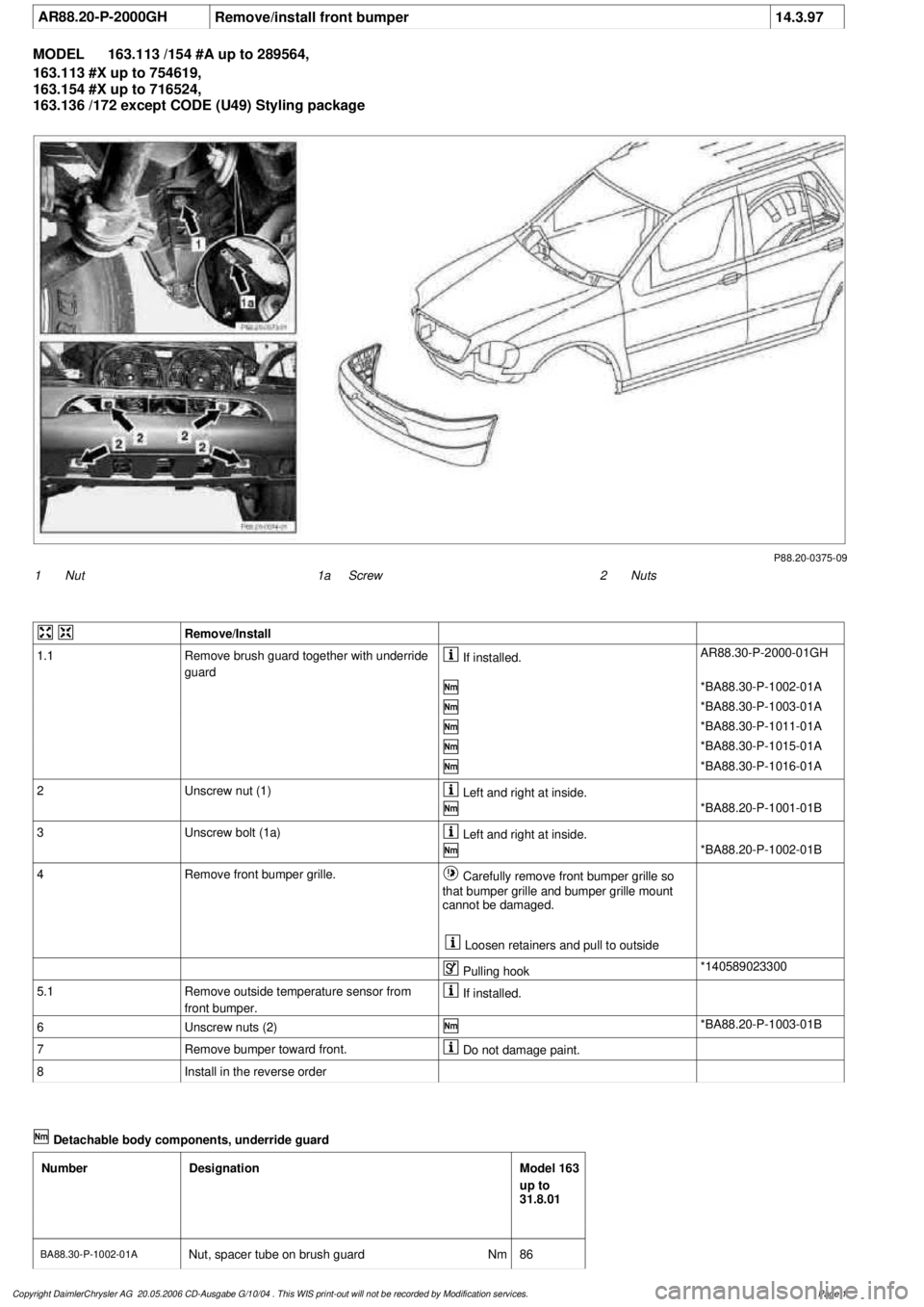
P88.20-0375-09
1
Nut
2
Nuts
1a
Screw
Remove/Install
1.1
Remove brush guard together with underride
guard
If installed.
AR88.30-P-2000-01GH
*BA88.30-P-1002-01A
*BA88.30-P-1003-01A
*BA88.30-P-1011-01A
*BA88.30-P-1015-01A
*BA88.30-P-1016-01A
2
Unscrew nut (1)
Left and right at inside.
*BA88.20-P-1001-01B
3
Unscrew bolt (1a)
Left and right at inside.
*BA88.20-P-1002-01B
4
Remove front bumper grille.
Carefully remove front bumper grille so
that bumper grille and bumper grille mount
cannot be damaged.
Loosen retainers and pull to outside
Pulling hook
*140589023300
5.1
Remove outside temperature sensor from
front bumper.
If installed.
6
Unscrew nuts (2)
*BA88.20-P-1003-01B
7
Remove bumper toward front.
Do not damage paint.
8
Install in the reverse order
Detachable body components, underride guard
Number
Designation
Model 163
up to
31.8.01
BA88.30-P-1002-01A
Nut, spacer tube on brush guard
Nm
86
Copyright DaimlerChrysler AG 20.05.2006 CD-Ausgabe G/10/04 . This WIS print-out will not be recorde
d by Modification services.
Page 1
Page 1996 of 4133
AR88.20-P-2000GJ
Remove/install front bumper
26.2.01
MODEL
163.113 /154 #A as of 289565,
163.113 #X as of 754620,
163.128 /154 /157 /175 except CODE (U49) Styling package
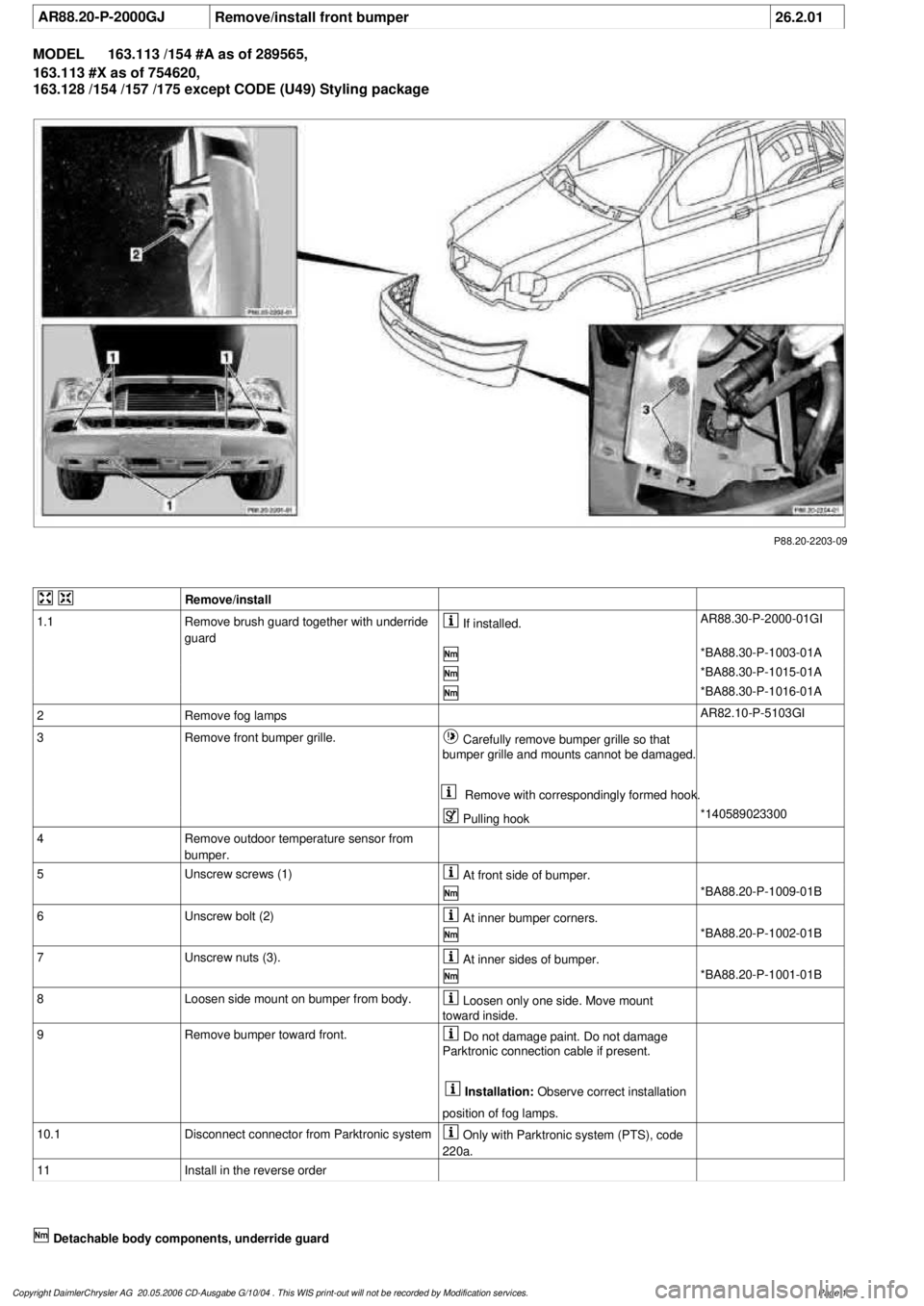
P88.20-2203-09
Remove/install
1.1
Remove brush guard together with underride
guard
If installed.
AR88.30-P-2000-01GI
*BA88.30-P-1003-01A
*BA88.30-P-1015-01A
*BA88.30-P-1016-01A
2
Remove fog lamps
AR82.10-P-5103GI
3
Remove front bumper grille.
Carefully remove bumper grille so that
bumper grille and mounts cannot be damaged.
Remove with correspondingly formed hook.
Pulling hook
*140589023300
4
Remove outdoor temperature sensor from
bumper.
5
Unscrew screws (1)
At front side of bumper.
*BA88.20-P-1009-01B
6
Unscrew bolt (2)
At inner bumper corners.
*BA88.20-P-1002-01B
7
Unscrew nuts (3).
At inner sides of bumper.
*BA88.20-P-1001-01B
8
Loosen side mount on bumper from body.
Loosen only one side. Move mount
toward inside.
9
Remove bumper toward front.
Do not damage paint. Do not damage
Parktronic connection cable if present.
Installation:
Observe correct installation
position of fog lamps.
10.1
Disconnect connector from Parktronic system
Only with Parktronic system (PTS), code
220a.
11
Install in the reverse order
Detachable body components, underride guard
Copyright DaimlerChrysler AG 20.05.2006 CD-Ausgabe G/10/04 . This WIS print-out will not be recorde
d by Modification services.
Page 1
Page 2001 of 4133
AR88.20-P-2200GH
Remove/install rear bumper
6.4.99
MODEL
163.113 #A up to 289564,
163.154 #X up to 754619,
163.154 #A up to 289564,
163.136 /172
P88.20-0372-09
A
Covers
C
Screws
B
Nuts
Remove/install
1.1
Disconnect antenna connector of E-call
emergency call system
Only with emergency call system E-Call,
code 349.
Connector is located behind side flap of right
C-pillar paneling at jack mounting point.
2
Remove covers (A)
Do not damage paint. Do not break off
clips.
Installation wedge
*115589035900
3
Unscrew mounting nuts (B) from bumper
*BA88.20-P-1004-01B
4
Unscrew screws (C)
*BA88.20-P-1005-01B
5.1
Remove nut from rear mud guard
Only if present
*BA88.30-P-1004-01A
6
Remove bumper toward rear
Do not damage paint.
Installation:
Align bumper at tailgate and
at taillamps
7.1
Remove rubber seal for E-call emergency call
system antenna from body at right
Only with emergency call system E-Call,
code 349.
8
Install in the reverse order
Bumper
Number
Designation
Model 163
BA88.20-P-1004-01B
Nut, rear bumper to frame
Nm
8
BA88.20-P-1005-01BScrews, rear bumper on frame
Nm
8
Copyright DaimlerChrysler AG 20.05.2006 CD-Ausgabe G/10/04 . This WIS print-out will not be recorde
d by Modification services.
Page 1
Page 2004 of 4133
AR88.20-P-2200GK
Remove/install rear bumper
26.2.01
MODEL
163.113 #A as of 289565,
163.113 #X as of 754620,
163.154 #A as of 289565,
163.128 /157 /175
P88.20-2200-09
Remove/Install
1.1
Disconnect antenna connector of E-call
emergency call system
Only with emergency call system E-Call,
code 349.
The connector is located behind side flap on
right C-pillar paneling at vehicle jacking point.
2
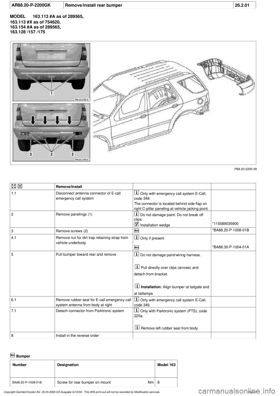
Remove panelings (1)
Do not damage paint. Do not break off
clips.
Installation wedge
*115589035900
3
Remove screws (2)
*BA88.20-P-1008-01B
4.1
Remove nut for dirt trap retaining strap from
vehicle underbody
Only if present
*BA88.30-P-1004-01A
5
Pull bumper toward rear and remove
Do not damage paint/wiring harness.
Pull directly over clips (arrows) and
detach from bracket.
Installation:
Align bumper at tailgate and
at taillamps
6.1
Remove rubber seal for E-call emergency call
system antenna from body at right
Only with emergency call system E-Call,
code 349.
7.1
Detach connector from Parktronic system
Only with Parktronic system (PTS), code
220a.
Remove left rubber seal from body.
8
Install in the reverse order
Bumper
Number
Designation
Model 163
BA88.20-P-1008-01B
Screw for rear bumper on mount
Nm
8
Copyright DaimlerChrysler AG 20.05.2006 CD-Ausgabe G/10/04 . This WIS print-out will not be recorde
d by Modification services.
Page 1
Page 2011 of 4133
AR68.20-P-2310GI
Remove/install cover on gearshift lever
26.2.01
MODEL
163.113 /154 /174 #A as of 289565,
163.113 #X as of 754620,
163.128 /157 /175
P68.20-2545-01
1
Armrest cover
2
Stowage box
3
Bolts
4
Cover on shift lever
5
Plastic screws
P68.20-2456-01
Remove/install
1
Remove armrest lid (1)
AR68.20-P-2370GH
2
Remove plastic screws (5)
3
Remove stowage box (2)
Press the pin in the center of the rivet
downwards for about 4 mm; then remove the
rivet from above.
4
Remove selector lever paneling
Long wedge
*115589035900
5
Unscrew bolts (3)
6Remove cover (4) from above
Carefully prize open at front (arrows) and
at the sides.
Long wedge
*115589035900
7
Detach connector from lower control panel
control module
3 connector.
8
Install in the reverse order
Assembly wedge
115 589 03 59 00
Copyright DaimlerChrysler AG 09.05.2006 CD-Ausgabe G/10/04 . This WIS print-out will not be recorde
d by Modification services.
Page 1
Page 2016 of 4133
AR68.20-P-2210GH
Remove/install rear center console switch module
25.5.01
MODEL
163.113 /154 /174 #A as of 289565,
163.113 #X as of 754620,
163.128 /157 /175
P68.20-2495-11
1
Rear center console.
2
Retaining clamps
3
Bolts
N72/2
RCP [HBF] control module
Remove/install
1
Remove rear center console (1)
AR68.20-P-2020GI
2
Remove retaining clamps RCP control
module (N72/2) from rear center console (1)
Press retaining clamps (2) toward inside.
3
Unscrew bolts (3) on RCP control module
(N72/2) from cover
4
Install in the reverse order
Copyright DaimlerChrysler AG 09.05.2006 CD-Ausgabe G/10/04 . This WIS print-out will not be recorde
d by Modification services.
Page 1