1997 MERCEDES-BENZ ML500 tow
[x] Cancel search: towPage 2096 of 4133

16
Remove poly V-belt (8)
Installation:
Lock tensioning device with
a drift or pin (diameter 5 mm).
Model 163.154 /157 /172.
AR13.22-P-1202B
Model 163.174 /175.
AR13.22-P-1202BA
17
Detach the coolant line (16) at the cylinder
head on the left
6 mm socket hexagon
*WH58.30-Z-1001-06A
7 mm socket hexagon
*WH58.30-Z-1002-06A
18.1
Remove fender liner (9)
Only with engine 113.113.942 /965 / 981.
AR88.10-P-1300GH
19.1
Remove shield (10)
Only with engine 113.942 /965 /981.
20.1
Remove exhaust bracket (11)
Only with engine 113.942 /965 /981.
Support exhaust system.
21
Detach exhaust system at exhaust manifold
Installation:
On vehicles with engine
damage, the exhaust system must be
examined for swarfs before assembling and
any swarfs present must be removed, in order
to avoid consequential damage.
*BA14.10-P-1002-01B
22
Position crankshaft to 40° after ignition TDC
on cylinder 1
The engine must not be turned back;
otherwise the timing chain can get jammed.
AR05.10-P-6858V
Rotate engine at the crankshaft in running
direction until scribe mark 40° on pulley/
vibration damper corresponds with scribe
mark on timing case.
The grooves on the camshafts must be
pointing toward the inner V.
23
Lock camshafts with locating plates
Locating plate
*112589003200
Locating plate
*112589013200
24
Remove chain tensioner (17)
Model 163.154 /157 with engine 112.942/
970, model 163.172 with engine 113.942.
AR05.10-P-7800C
Model 163.174 /175 with engine 113.981/ 965.
AR05.10-P-7800CA
25.1
Remove oil filter housing (18) together with oil-
water heat exchanger
Engine 113.942.
AR18.20-P-3471B
Engine 112.942/970.
AR18.20-P-3471BA
26
Unscrew camshaft sprockets (19)
If camshaft sprockets are removed,
engine must no longer be cranked, otherwise
timing chain might jam.
Engine 113.942 /965 /981:
#
Tie timing chain tight on both camshaft
sprockets with tie straps.
Engine 112.942 /970:
#
Right-hand camshaft sprocket:
Tie timing chain tight on camshaft sprocket
with tie strap.
Left-hand camshaft sprocket:
Mark camshaft sprocket to timing chain and
remove camshaft sprocket.
It is not possible for the timing chain to
jump across at the crankshaft and balancing
shaft.
After installation:
#
Inspect basic position of camshafts.
AR05.10-P-6858V
If necessary after checking:
#
Set the basic position of camshafts
AR05.20-P-6020AU
Open-end wrench
*112589000100
Insertion tool
*112589010300
Torque wrench
*001589722100
*BA05.20-P-1001-01B
27
Remove camshaft bearing bridges (28)
Pay attention to slackening and tightening
pattern!
AR05.20-P-7103AU
28
Unscrew bolts, cylinder head
!
timing case
cover (20)
*BA01.40-P-1002-01C
Copyright DaimlerChrysler AG 20.05.2006 CD-Ausgabe G/10/04 . This WIS print-out will not be recorde
d by Modification services.
Page 4
Page 2112 of 4133
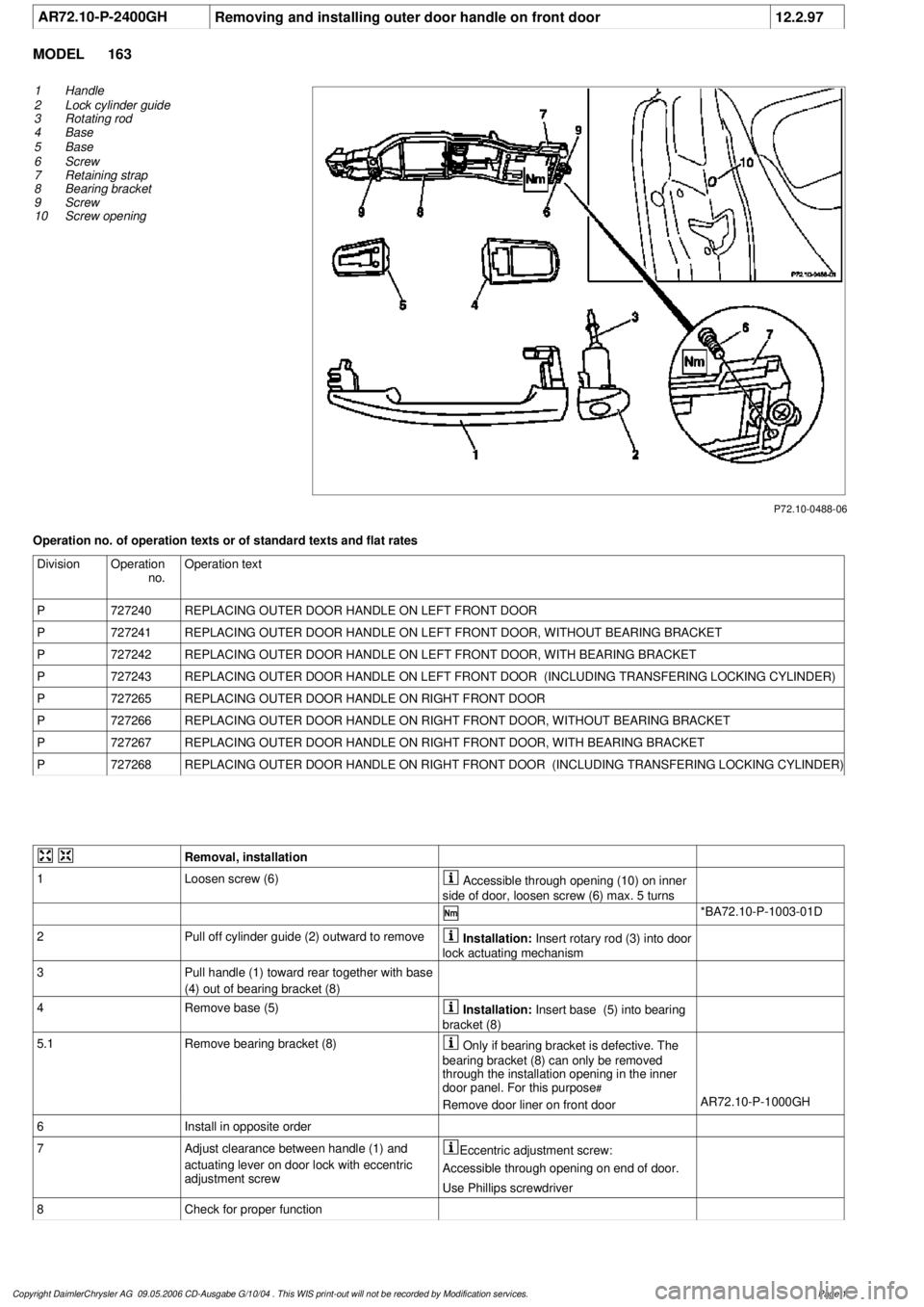
AR72.10-P-2400GH
Removing and installing outer door handle on front door
12.2.97
MODEL
163
P72.10-0488-06
1
Handle
2
Lock cylinder guide
3
Rotating rod
4
Base
5
Base
6
Screw
7
Retaining strap
8
Bearing bracket
9
Screw
10
Screw opening
Operation no. of operation texts or of standard texts and flat rates
Division
Operation
no.
Operation text
P
727240
REPLACING OUTER DOOR HANDLE ON LEFT FRONT DOOR
P
727241
REPLACING OUTER DOOR HANDLE ON LEFT FRONT DOOR, WITHOUT BEARING BRACKET
P
727242
REPLACING OUTER DOOR HANDLE ON LEFT FRONT DOOR, WITH BEARING BRACKET
P
727243
REPLACING OUTER DOOR HANDLE ON LEFT FRONT DOOR (INCLUDING TRANSFERING LOCKING CYLINDER)
P
727265
REPLACING OUTER DOOR HANDLE ON RIGHT FRONT DOOR
P
727266
REPLACING OUTER DOOR HANDLE ON RIGHT FRONT DOOR, WITHOUT BEARING BRACKET
P
727267
REPLACING OUTER DOOR HANDLE ON RIGHT FRONT DOOR, WITH BEARING BRACKET
P
727268
REPLACING OUTER DOOR HANDLE ON RIGHT FRONT DOOR (INCLUDING TRANSFERING LOCKING CYLINDER)
Removal, installation
1
Loosen screw (6)
Accessible through opening (10) on inner
side of door, loosen screw (6) max. 5 turns
*BA72.10-P-1003-01D
2
Pull off cylinder guide (2) outward to remove
Installation:
Insert rotary rod (3) into door
lock actuating mechanism
3
Pull handle (1) toward rear together with base
(4) out of bearing bracket (8)
4
Remove base (5)
Installation:
Insert base (5) into bearing
bracket (8)
5.1
Remove bearing bracket (8)
Only if bearing bracket is defective. The
bearing bracket (8) can only be removed
through the installation opening in the inner
door panel. For this purpose
#
Remove door liner on front door
AR72.10-P-1000GH
6
Install in opposite order
7
Adjust clearance between handle (1) and
actuating lever on door lock with eccentric
adjustment screw
Eccentric adjustment screw:
Accessible through opening on end of door.
Use Phillips screwdriver
8
Check for proper function
Copyright DaimlerChrysler AG 09.05.2006 CD-Ausgabe G/10/04 . This WIS print-out will not be recorde
d by Modification services.
Page 1
Page 2120 of 4133
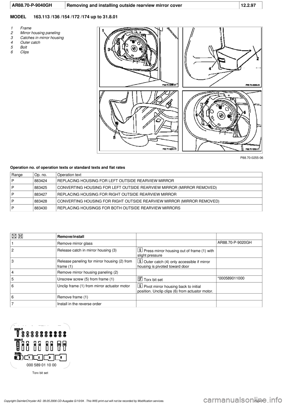
AR88.70-P-9040GH
Removing and installing outside rearview mirror cover
12.2.97
MODEL
163.113 /136 /154 /172 /174 up to 31.8.01
P88.70-0255-06
1
Frame
2
Mirror housing paneling
3
Catches in mirror housing
4
Outer catch
5
Bolt
6
Clips
Operation no. of operation texts or standard texts and flat rates
Range
Op. no.
Operation text
P
883424
REPLACING HOUSING FOR LEFT OUTSIDE REARVIEW MIRROR
P
883425
CONVERTING HOUSING FOR LEFT OUTSIDE REARVIEW MIRROR (MIRROR REMOVED)
P
883427
REPLACING HOUSING FOR RIGHT OUTSIDE REARVIEW MIRROR
P
883428
CONVERTING HOUSING FOR RIGHT OUTSIDE REARVIEW MIRROR (MIRROR REMOVED)
P
883430
REPLACING HOUSINGS FOR BOTH OUTSIDE REARVIEW MIRRORS
Remove/install
1
Remove mirror glass
AR88.70-P-9020GH
2
Release catch in mirror housing (3)
Press mirror housing out of frame (1) with
slight pressure
3
Release paneling for mirror housing (2) from
frame (1)
Outer catch (4) only accessible if mirror
housing is pivoted toward door
4
Remove mirror housing paneling (2)
5
Unscrew screw (5) from frame (1)
Torx bit set
*000589011000
6
Unclip frame (1) from mirror actuator motor
Pivot mirror housing back to initial
position. Unclip clips (6) from actuator motor.
6
Remove frame (1)
7
Install in the reverse order
Torx bit set
000 589 01 10 00
Copyright DaimlerChrysler AG 09.05.2006 CD-Ausgabe G/10/04 . This WIS print-out will not be recorde
d by Modification services.
Page 1
Page 2219 of 4133
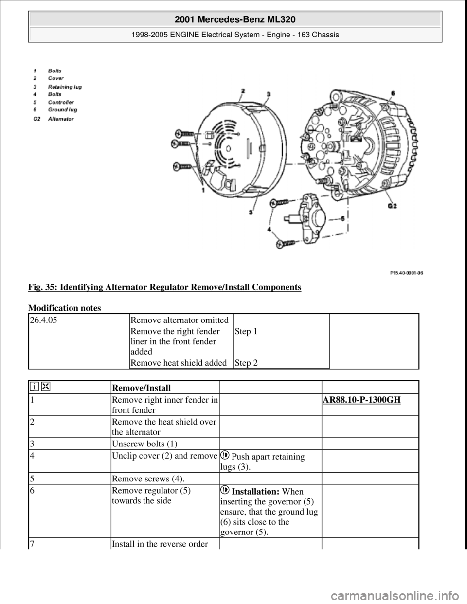
Fig. 35: Identifying Alternator Regulator Remove/Install Components
Modification notes
26.4.05Remove alternator omitted
Remove the right fender
liner in the front fender
addedStep 1
Remove heat shield addedStep 2
Remove/Install
1Remove right inner fender in
front fender AR88.10-P-1300GH
2Remove the heat shield over
the alternator
3Unscrew bolts (1)
4Unclip cover (2) and remove Push apart retaining
lugs (3).
5Remove screws (4).
6Remove regulator (5)
towards the side Installation: When
inserting the governor (5)
ensure, that the ground lug
(6) sits close to the
governor (5).
7Install in the reverse order
2001 Mercedes-Benz ML320
1998-2005 ENGINE Electrical System - Engine - 163 Chassis
me
Saturday, October 02, 2010 3:18:55 PMPage 65 © 2006 Mitchell Repair Information Company, LLC.
Page 2247 of 4133
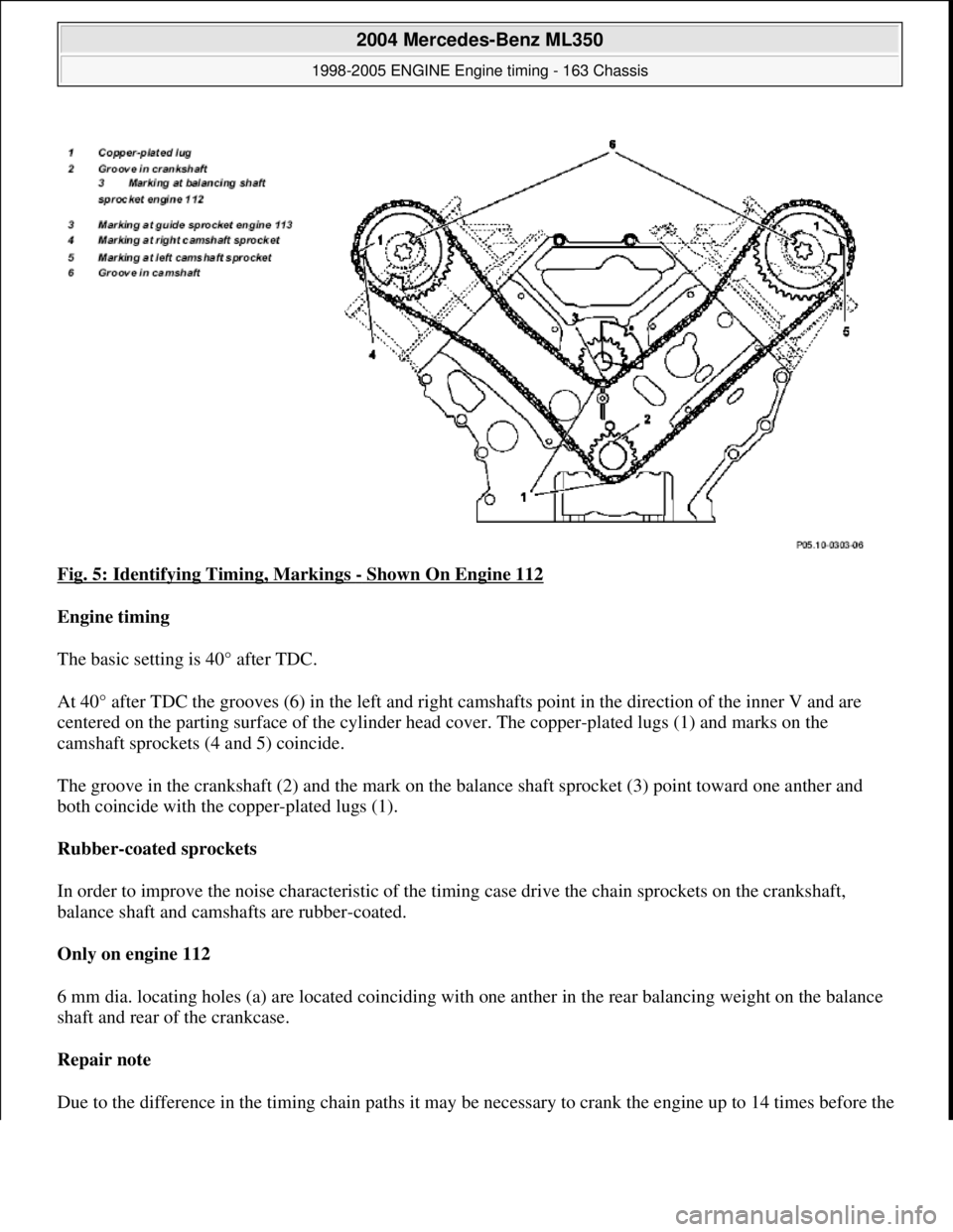
Fig. 5: Identifying Timing, Markings - Shown On Engine 112
Engine timing
The basic setting is 40° after TDC.
At 40° after TDC the grooves (6) in th e left and right camshafts point in the direction of the inner V and are
centered on the parting surface of the cylinder head cover. The copper-plated lugs (1) and marks on the
camshaft sprockets (4 and 5) coincide.
The groove in the crankshaft (2) and the mark on the ba lance shaft sprocket (3) point toward one anther and
both coincide with the copper-plated lugs (1).
Rubber-coated sprockets
In order to improve the noise characteristic of the timing case drive the chain sprockets on the crankshaft,
balance shaft and camshafts are rubber-coated.
Only on engine 112
6 mm dia. locating holes (a) are located coinciding with one anther in the rear balancing weight on the balance
shaft and rear of the crankcase.
Repair note
Due to the difference in the timin
g chain paths it may be necessary to crank the engine up to 14 times before the
2004 Mercedes-Benz ML350
1998-2005 ENGINE Engine timing - 163 Chassis
me
Saturday, October 02, 2010 3:39:37 PMPage 6 © 2006 Mitchell Repair Information Company, LLC.
Page 2248 of 4133
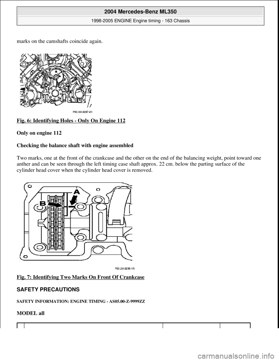
marks on the camshafts coincide again.
Fig. 6: Identifying Holes
- Only On Engine 112
Only on engine 112
Checking the balance shaft with engine assembled
Two marks, one at the front of the crankcase and the ot her on the end of the balancing weight, point toward one
anther and can be seen through the left timing case shaft approx. 22 cm. below the parting surface of the
cylinder head cover when the cylinder head cover is removed.
Fig. 7: Identifying Two Mark s On Front Of Crankcase
SAFETY PRECAUTIONS
SAFETY INFORMATION: ENGI NE TIMING - AS05.00-Z-9999ZZ
MODEL all
2004 Mercedes-Benz ML350
1998-2005 ENGINE Engine timing - 163 Chassis
me
Saturday, October 02, 2010 3:39:37 PMPage 7 © 2006 Mitchell Repair Information Company, LLC.
Page 2288 of 4133
Oil pan
Oil pan
Model 220 except 220.074 /174
with engine 113
Do not remove top part of oil
pan!
Model 463AR01.40-P-8000GV
Do not remove top part of oil
pan!
Model 210 with 4MATICAR01.40-P-8000GV
Models
203.061 /064 /065 /081 /084 /261/
264 /265 /281 /284 /076 /276AR01.40-P-8000V
Models 209.361/365/ 375/ 376/
461/ 465/ 475/ 476AR01.40-P-8000PV
Models 211.061 / 065/ 070/ 080/
082/ 083/ 280/ 282/ 283
Models 220.074/174AR01.40-P-8000RVK
Model 215.374
Model 203.764
Models 210.062/262
Models 215.373/375
8Remove slide rails (1) At the same time detach slide
rails (1) toward front from the
retaining bolts.
9Install in the reverse
order
NumberDesignationEngines
112.910/911/
912/913/914/
915/917/920/
921/922/923/
940/941/942/
943/944/945/
946/947/949/
951/954/955/
960/961/970/
972/973/976Engines
113.940/941/
942/943/944/
945/946/960/
961/962/963/
965/967/968/
969/980/981/
982/984/986/
992/995
BA01.45-P-1003-
01BOil drain screw
to oil panM14Nm3030
NumberDesignationEngine
112.916/953/975, Engine 113.987/
988/991
2004 Mercedes-Benz ML350
1998-2005 ENGINE Engine timing - 163 Chassis
me
Saturday, October 02, 2010 3:39:38 PMPage 47 © 2006 Mitchell Repair Information Company, LLC.
Page 2296 of 4133
i040*WH58.30-Z-
1003-28A
3Place camshaft bearing
bridge on board (4) Fig. 56
4
Remove the rocker arm
spindle (3) by tapping
gently with a hammer If it is tapped very hard, th ere is a danger of distorting the
camshaft bearing bridge and da maging the hollow rocker arm
spindle (3).
Fig. 53
Check
5
Inspect bearing
surfaces of rocker arms
for damage Pay attention to any long score marks caused by the
removal of the rocker arm spindl es (3). Replace the rocker arm
if damaged.
Installing
6
Insert the guide shafts
into the camshaft
bearing bridge. At the same time, preassemble the rocker arm on guide
shaft.
Fig. 54
Fig. 55
Risk of injury to skin
and eyes caused by
handling hot or glowing
objects.
Wear safety gloves, protective cl othing and safety glasses, if
necessary.AS00.00-Z-
0002-01A
7
Heat camshaft bearing
bridge to approx. 150°
C
Heat the camshaft bearing bridge uniformly, but do not
heat it over 160°C; there is a danger of structural changes.
WH58.30-Z-
1001-28A
*WH58.30-Z-
1003-28A
8Cool the rocker arm
spindle (3)
9
Place heated camshaft
bearing bridge on board
(4) Fig. 56
10Install rocker arm
spindle (3)
Insert the rocker arm spindle (3) in the camshaft bearing
bridge by tapping gently with a hammer and simultaneously
remove the guide shaft. Ensure that the rocker arms do not get
jammed.
11Align the rocker arm
spindle (3)
In order to align and secure the rocker arm spindle (3), fit
two screws through the mount ing bores in the camshaft
bearing bridge. The oil supply bores of the rocker arm spindle
(3) point towards the cylinder head.
Engines 112, 113 except engines 113.967 /990 in models 219,
engines 113.964 /971 /989 /993AR05.20-P-
7103AU
Engine 113.993 in model 463AR05.20-P-
7103GX
2004 Mercedes-Benz ML350
1998-2005 ENGINE Engine timing - 163 Chassis
me
Saturday, October 02, 2010 3:39:38 PMPage 55 © 2006 Mitchell Repair Information Company, LLC.