1997 MERCEDES-BENZ ML500 tow
[x] Cancel search: towPage 2306 of 4133
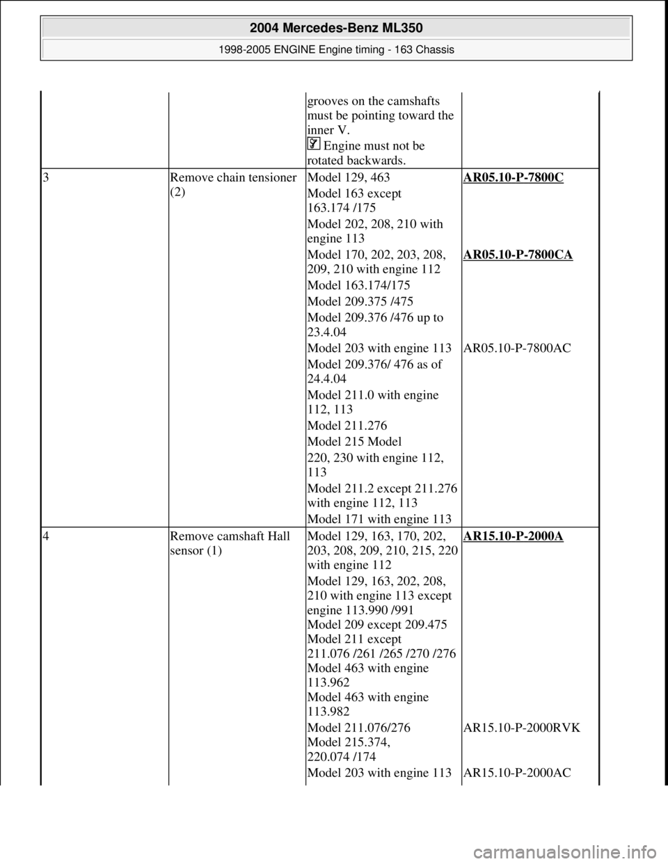
grooves on the camshafts
must be pointing toward the
inner V.
Engine must not be
rotated backwards.
3Remove chain tensioner
(2)Model 129, 463AR05.10-P-7800C
Model 163 except
163.174 /175
Model 202, 208, 210 with
engine 113
Model 170, 202, 203, 208,
209, 210 with engine 112AR05.10-P-7800CA
Model 163.174/175
Model 209.375 /475
Model 209.376 /476 up to
23.4.04
Model 203 with engine 113AR05.10-P-7800AC
Model 209.376/ 476 as of
24.4.04
Model 211.0 with engine
112, 113
Model 211.276
Model 215 Model
220, 230 with engine 112,
113
Model 211.2 except 211.276
with engine 112, 113
Model 171 with engine 113
4Remove camshaft Hall
sensor (1)Model 129, 163, 170, 202,
203, 208, 209, 210, 215, 220
with engine 112AR15.10-P-2000A
Model 129, 163, 202, 208,
210 with engine 113 except
engine 113.990 /991
Model 209 except 209.475
Model 211 except
211.076 /261 /265 /270 /276
Model 463 with engine
113.962
Model 463 with engine
113.982
Model 211.076/276
Model 215.374,
220.074 /174AR15.10-P-2000RVK
Model 203 with engine 113AR15.10-P-2000AC
2004 Mercedes-Benz ML350
1998-2005 ENGINE Engine timing - 163 Chassis
me
Saturday, October 02, 2010 3:39:38 PMPage 65 © 2006 Mitchell Repair Information Company, LLC.
Page 2313 of 4133
Camshaft
Remove/install
1Remove
cylinder head
coverAir filter located at vehicle side.AR01.20-
P-5014B
Air filter located on engine side.AR01.20-
P-5014BV
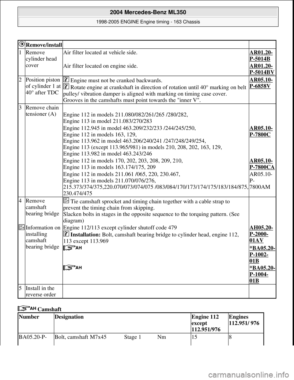
2Position piston
of cylinder 1 at
40° after TDC Engine must not be cranked backwards.
Rotate engine at crankshaft in direct ion of rotation until 40° marking on belt
pulley/ vibration damper is aligned with marking on timing case cover.
Grooves in the camshafts must point towards the "inner V".AR05.10-
P-6858V
3Remove chain
tensioner (A)
Engine 112 in models 211.080/082/261/265 /280/282,
Engine 113 in model 211.083/270/283
Engine 112.945 in model 463.209/232/233 /244/245/250,
Engine 112 in models 163, 129,
Engine 113.962 in model 463.206/240/241 /247/248/249/254,
Engine 113 (except 113.965/981) in models 210, 208, 202, 163, 129,
Engine 113.982 in model 463.243/246AR05.10-
P-7800C
Engine 112 in models 170, 202, 203, 208, 209, 210,
Engine 113 in models 163.174/175, 209AR05.10-
P-7800CA
Engine 112 in models 211.061 /065, 220, 230.467,
Engine 113 in models 211.070/076/276,
215.373/374/375,220.070/073/074/075 /083/ 084/170/173/174/175/183/184/875,
230.474/475AR05.10-
P-
7800AM
4Remove
camshaft
bearing bridge Tie camshaft sprocket and timing ch ain together with a cable strap to
prevent the timing chain from skipping.
Slacken bolts in stages in the opposite sequence to the torquing pattern. (See
diagram)
Information on
installing
camshaft
bearing bridgeEngine 112/113 except cylinder shutoff code 479
Installation: Bolt, camshaft bearing bridge to cylinder head, engine 112,
113 except 113.969AH05.20-
P-2000-
01AV
*BA05.20-
P-1002-
01B
*BA05.20-
P-1004-
01B
5Install in the
reverse order
NumberDesignationEngine 112
except
112.951/976Engines
112.951/ 976
BA05.20-P- Bolt, camshaft M7x45Stage 1Nm158
2004 Mercedes-Benz ML350
1998-2005 ENGINE Engine timing - 163 Chassis
me
Saturday, October 02, 2010 3:39:38 PMPage 72 © 2006 Mitchell Repair Information Company, LLC.
Page 2413 of 4133
two bottom bolts at transmission bell.
*BA27.40-P-
1008-01A
34Unscrew nuts (18)
for engine mount Before unscrewing left engine mount, press
oil line of power stee ring out of fixture.
*BA22.10-P-
1001-01L
35Unscrew oil filler
pipe (automatic
transmission) at right
cylinder head cover
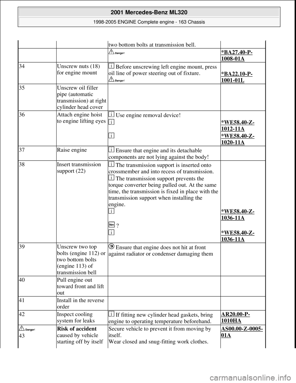
36Attach engine hoist
to engine lifting eyes Use engine removal device!
*WE58.40-Z-
1012-11A
*WE58.40-Z-
1020-11A
37Raise engine Ensure that engine and its detachable
components are not lying against the body!
38Insert transmission
support (22) The transmission support is inserted onto
crossmember and into recess of transmission.
The transmission support prevents the
torque converter being pulled out. At the same
time, the transmission is fixed in place with the
transmission support when installing the
engine.
*WE58.40-Z-
1036-11A
?
*WE58.40-Z-
1036-11A
39Unscrew two top
bolts (engine 112) or
two bottom bolts
(engine 113) of
transmission bell Ensure that engine does not hit at front
against radiator or condenser damaging them
40Pull engine out
toward front and lift
out
41Install in the reverse
order
42Inspect cooling
system for leaks If fitting new cylinder head gaskets, bring
engine to operating temperature beforehand.AR20.00-P-
1010HA
43Risk of accident
caused by vehicle
starting off by itself Secure vehicle to prev ent it from moving by
itself.
Wear closed and snug-fitting work clothes. AS00.00-Z-0005-
01A
2001 Mercedes-Benz ML320
1998-2005 ENGINE Complete engine - 163 Chassis
me
Saturday, October 02, 2010 3:17:56 PMPage 57 © 2006 Mitchell Repair Information Company, LLC.
Page 2428 of 4133
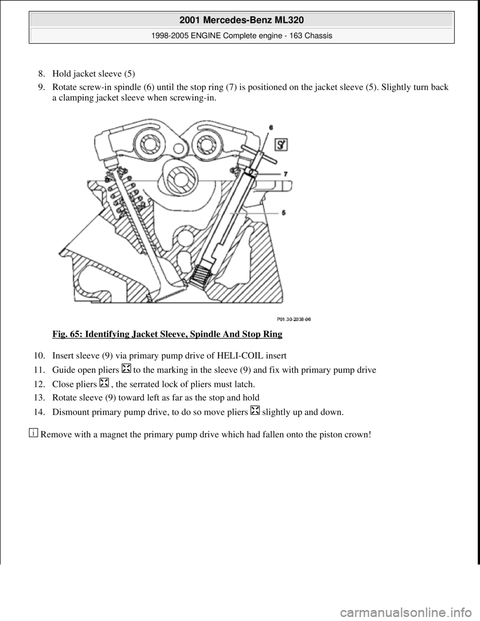
8. Hold jacket sleeve (5)
9. Rotate screw-in spindle (6) until the stop ring (7) is pos itioned on the jacket sleeve (5). Slightly turn back
a clamping jacket sleeve when screwing-in.
Fig. 65: Identifying Jacket Sleeve, Spindle And Stop Ring
10. Insert sleeve (9) via primary pum p drive of HELI-COIL insert
11. Guide open pliers to the marking in the sleeve (9) and fix with primary pump drive
12. Close pliers , the serrated lock of pliers must latch.
13. Rotate sleeve (9) toward left as far as the stop and hold
14. Dismount primary pump drive, to do so move pliers slightly up and down.
Remove with a ma
gnet the primary pump drive which had fallen onto the piston crown!
2001 Mercedes-Benz ML320
1998-2005 ENGINE Complete engine - 163 Chassis
me
Saturday, October 02, 2010 3:17:56 PMPage 72 © 2006 Mitchell Repair Information Company, LLC.
Page 2444 of 4133
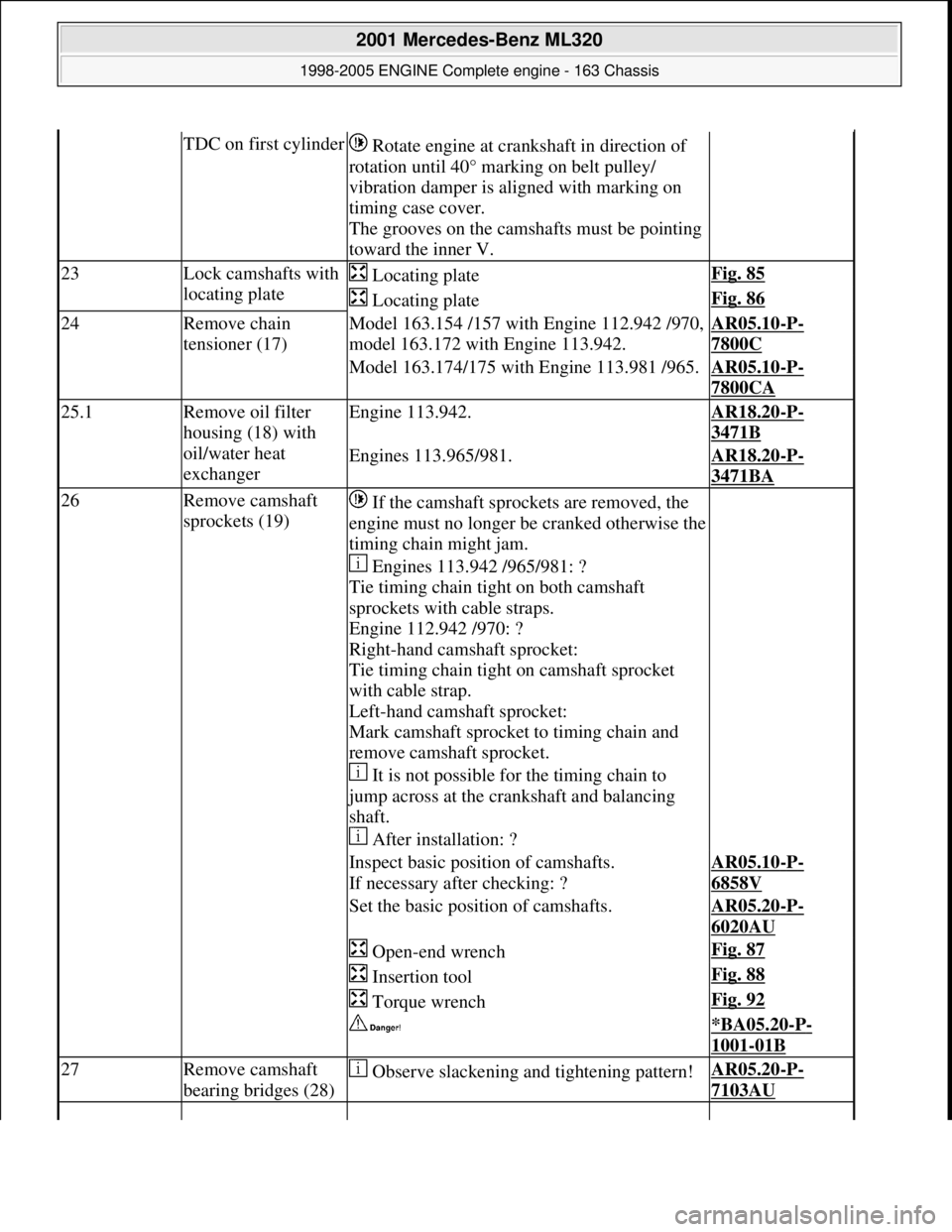
TDC on first cylinder Rotate engine at cra nkshaft in direction of
rotation until 40° marking on belt pulley/
vibration damper is al igned with marking on
timing case cover.
The grooves on the camshafts must be pointing
toward the inner V.
23Lock camshafts with
locating plate Locating plateFig. 85
Locating plateFig. 86
24Remove chain
tensioner (17)Model 163.154 /157 with Engine 112.942 /970,
model 163.172 with Engine 113.942.AR05.10-P-
7800C
Model 163.174/175 with Engine 113.981 /965.AR05.10-P-
7800CA
25.1Remove oil filter
housing (18) with
oil/water heat
exchangerEngine 113.942.AR18.20-P-
3471B
Engines 113.965/981.AR18.20-P-
3471BA
26Remove camshaft
sprockets (19) If the camshaft sprockets are removed, the
engine must no longer be cranked otherwise the
timing chain might jam.
Engines 113.942 /965/981: ?
Tie timing chain tight on both camshaft
sprockets with cable straps.
Engine 112.942 /970: ?
Right-hand camshaft sprocket:
Tie timing chain tight on camshaft sprocket
with cable strap.
Left-hand camshaft sprocket:
Mark camshaft sprocket to timing chain and
remove camshaft sprocket.
It is not possible for the timing chain to
jump across at the crankshaft and balancing
shaft.
After installation: ?
Inspect basic positi on of camshafts.
If necessary after checking: ?AR05.10-P-
6858V
Set the basic position of camshafts.AR05.20-P-
6020AU
Open-end wrenchFig. 87
Insertion toolFig. 88
Torque wrenchFig. 92
*BA05.20-P-
1001-01B
27Remove camshaft
bearing bridges (28) Observe slackening and tightening pattern!AR05.20-P-
7103AU
2001 Mercedes-Benz ML320
1998-2005 ENGINE Complete engine - 163 Chassis
me
Saturday, October 02, 2010 3:17:57 PMPage 88 © 2006 Mitchell Repair Information Company, LLC.
Page 2609 of 4133

Remove, Install
Danger!
Risk of explosion
from fuel igniting,
risk of
poisoning
from inhaling and swallowing fuel
as well as
risk of injury
to eyes and skin
from contact with fuel.
Fire, sparks, open flames or smoking
forbidden.
Pour fuels only into suitable and appropriately
marked containers.
Wear protective clothing when handling fuel.
AS47.00-Z-0001-01A
1
Drain fuel tank
Via fuel pump. NOT for model 163.113/128.
AR47.10-P-4001GH
If fuel pump faulty, and model 163.113/128.
AR47.10-P-4000GH
*BF47.10-P-1001-01A
2
Unscrew filler cap (2) and detach from filler
cap attachment (4)
3.1
Remove left seat of 3rd seat row
If installed. See owner's manual
4
Unclip cover of left-hand side panel (1)
5.1
Detach fuel lines of expansion reservoir and
separate from filler neck
As of VIN A289565. NOT for model
163.113/128.
6
Detach fuel filler neck from guide funnel
Installation:
Check O-ring and replace if
necessary. Ensure that the bayonet-lock
remains above
the pressure sensor.
Ensure it is correctly located when installed.
Open bayonet lock (3) to do this.
7
Pull filler neck through toward interior
Screw on cap again in order to avoid fuel
flowing out.
8.1
Remove fuel tank pressure sensor (B4/3)
Only USA version
AR47.10-P-8022GH
9.1
Detach bolted connection of fuel tank filler
neck/ground (X36/4) from filler neck
NOT for model 163.113/128.
10.1
Cut cable strap for retaining clips of fuel lines
at filler neck and remove retaining clips
As of VIN A289565. NOT for model
163.113/128.
Danger!
Risk of fatal accident
from vehicle slipping
or toppling off the lift platform
Align vehicle between the columns of lifting
platform and position the four support plates
below the support strongpoints specified by
the vehicle manufacturer.
AS00.00-Z-0010-01A
11
Place the vehicle on lifting platform
AR00.60-P-1000GH
12
Separate rubber seal (5) from underside of
vehicle and remove filler neck from interior
Do not damage fuel lines at filler neck.
13
Remove left rear wheel
e
Removing and installing wheels, rotating if
necessary
AP40.10-P-4050GH
14
Remove spare wheel and spare wheel carrier
complete
NOT in the case of spare wheel
holder/spare wheel, code 849.
15
Cut a large safety cable strap for filler neck at
bracket on longitudinal frame member
16
Remove bracket from longitudinal frame
member
17
Disconnect connection for regeneration (77/2)
and fresh air connection (77/4) on activated
charcoal canister (77)
Installation
: Connect up lines as per
connection diagram:
#
Engine 111
AR47.30-P-8212-01GJ
Engines 112, 113
AR47.30-P-8212-01GI
Engines 112, 113 version
I
AR47.30-P-8212-01GH
Charcoal canister and fuel tank form a
single unit.
NOT for model 163.113/128.
18
Detach vent hose
At rear differential to rear of activated
charcoal reservoir.
19
Remove rear exhaust system heat shield.
Do not damage boot at rear axle shaft.
20
Disconnect rear propeller shaft at differential
Installation:
Install new self-locking bolts.
Tie up propeller shaft e.g. using welding
wire
Heat bolts with hot air fan to facilitate
removing. Mark propeller shaft and differential
gear flange for correct installed position.
*BA41.10-P-1002-01C
Copyright DaimlerChrysler AG 28.05.2006 CD-Ausgabe G/10/04 . This WIS print-out will not be recorde
d by Modification services.
Page 2
Page 2655 of 4133
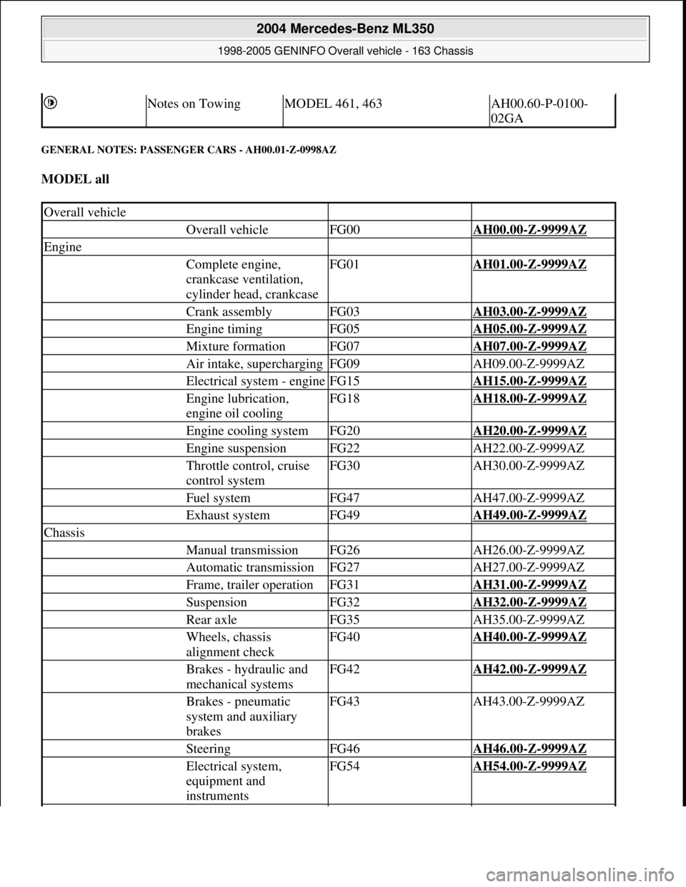
GENERAL NOTES: PASSENGER CARS - AH00.01-Z-0998AZ
MODEL all
Notes on TowingMODEL 461, 463AH00.60-P-0100-
02GA
Overall vehicle
Overall vehicleFG00AH00.00-Z-9999AZ
Engine
Complete engine,
crankcase ventilation,
cylinder head, crankcaseFG01AH01.00-Z-9999AZ
Crank assemblyFG03AH03.00-Z-9999AZ
Engine timingFG05AH05.00-Z-9999AZ
Mixture formationFG07AH07.00-Z-9999AZ
Air intake, superchargingFG09AH09.00-Z-9999AZ
Electrical system - engineFG15AH15.00-Z-9999AZ
Engine lubrication,
engine oil coolingFG18AH18.00-Z-9999AZ
Engine cooling systemFG20AH20.00-Z-9999AZ
Engine suspensionFG22AH22.00-Z-9999AZ
Throttle control, cruise
control systemFG30AH30.00-Z-9999AZ
Fuel systemFG47AH47.00-Z-9999AZ
Exhaust systemFG49AH49.00-Z-9999AZ
Chassis
Manual transmissionFG26AH26.00-Z-9999AZ
Automatic transmissionFG27AH27.00-Z-9999AZ
Frame, trailer operationFG31AH31.00-Z-9999AZ
SuspensionFG32AH32.00-Z-9999AZ
Rear axleFG35AH35.00-Z-9999AZ
Wheels, chassis
alignment checkFG40AH40.00-Z-9999AZ
Brakes - hydraulic and
mechanical systemsFG42AH42.00-Z-9999AZ
Brakes - pneumatic
system and auxiliary
brakesFG43AH43.00-Z-9999AZ
SteeringFG46AH46.00-Z-9999AZ
Electrical system,
equipment and
instrumentsFG54AH54.00-Z-9999AZ
2004 Mercedes-Benz ML350
1998-2005 GENINFO Overall vehicle - 163 Chassis
me
Saturday, October 02, 2010 3:47:44 PMPage 10 © 2006 Mitchell Repair Information Company, LLC.
Page 2849 of 4133
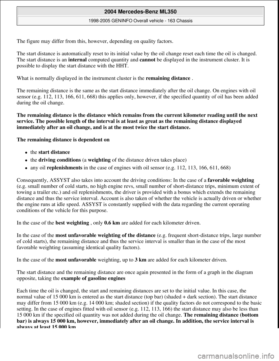
The figure may differ from this, however, depending on quality factors.
The start distance is automatically reset to its initial value by the oil change reset each time the oil is changed.
The start distance is an internal computed quantity and cannot be displayed in the instrument cluster. It is
possible to display the start distance with the HHT.
What is normally displayed in the instrument cluster is the remaining distance .
The remaining distance is the same as the start distance immediately after the oil change. On engines with oil
sensor (e.g. 112, 113, 166, 611, 668) this applies only, however, if the specified quantity of oil has been added
during the oil change.
The remaining distance is the distance which remains from the current kilometer reading until the next
service. The possible length of the interval is at least as great as the remaining distance displayed
immediately after an oil change, and is at the most twice the start distance.
The remaining distance is dependent on
the start distance
the driving conditions (a weighting of the distance driven takes place)
any oil replenishments in the case of engines with oil sensor (e.g. 112, 113, 166, 611, 668)
Consequently, ASSYST also takes into account the driving conditions: In the case of a favorable weighting
(e.g. small number of cold starts, no high engine revs, small number of short-distance trips, minimum extent of
towing a trailer etc.) and oil replenishments, the driver is provided with a bonus which extends the remaining
distance and thus the service interval. Account is also taken of whether the vehicle is actually driven or whether
the engine runs at idle speed. ASSYST is constantly supplied with the data regarding the current operating
conditions of the vehicle for this purpose.
In the case of the best weighting , only 0.6 km are added for each kilometer driven.
In the case of the most unfavorable weighting of the distance (e.g. frequent short-distance trips, large number
of cold starts), the remaining distance and thus the service interval is smaller than in the case of the most
favorable weighting (assuming identical quality factors).
In the case of the most unfavorable weighting, up to 3 km are added for each kilometer driven.
The start distance and the remaining distance are once again presented in the form of a graph in the diagram
opposite, taking the example of gasoline engines
Each time the oil is changed, the start and remaining distances are set to the initial value. In this case, the
normal value of 15 000 km is entered as the start distance (top bar) (shaded + dark section). The start distance
may differ from 15 000 km (e.g. 14 000 km; shaded section) if the quality factors do not correspond to the basic
setting. In the case of engines fitted with oil sensor (e.g. 112, 113, 166) the start distance may also be less than
15 000 km if the specified oil quantity was not added during the oil change. The remaining distance (bottom
bar) is always 15 000 km, however, immediately after an oil change. In addition, the service interval is
always at least 15 000 km .
2004 Mercedes-Benz ML350
1998-2005 GENINFO Overall vehicle - 163 Chassis
me
Saturday, October 02, 2010 3:47:47 PMPage 204 © 2006 Mitchell Repair Information Company, LLC.