1997 MERCEDES-BENZ ML500 tow
[x] Cancel search: towPage 2017 of 4133
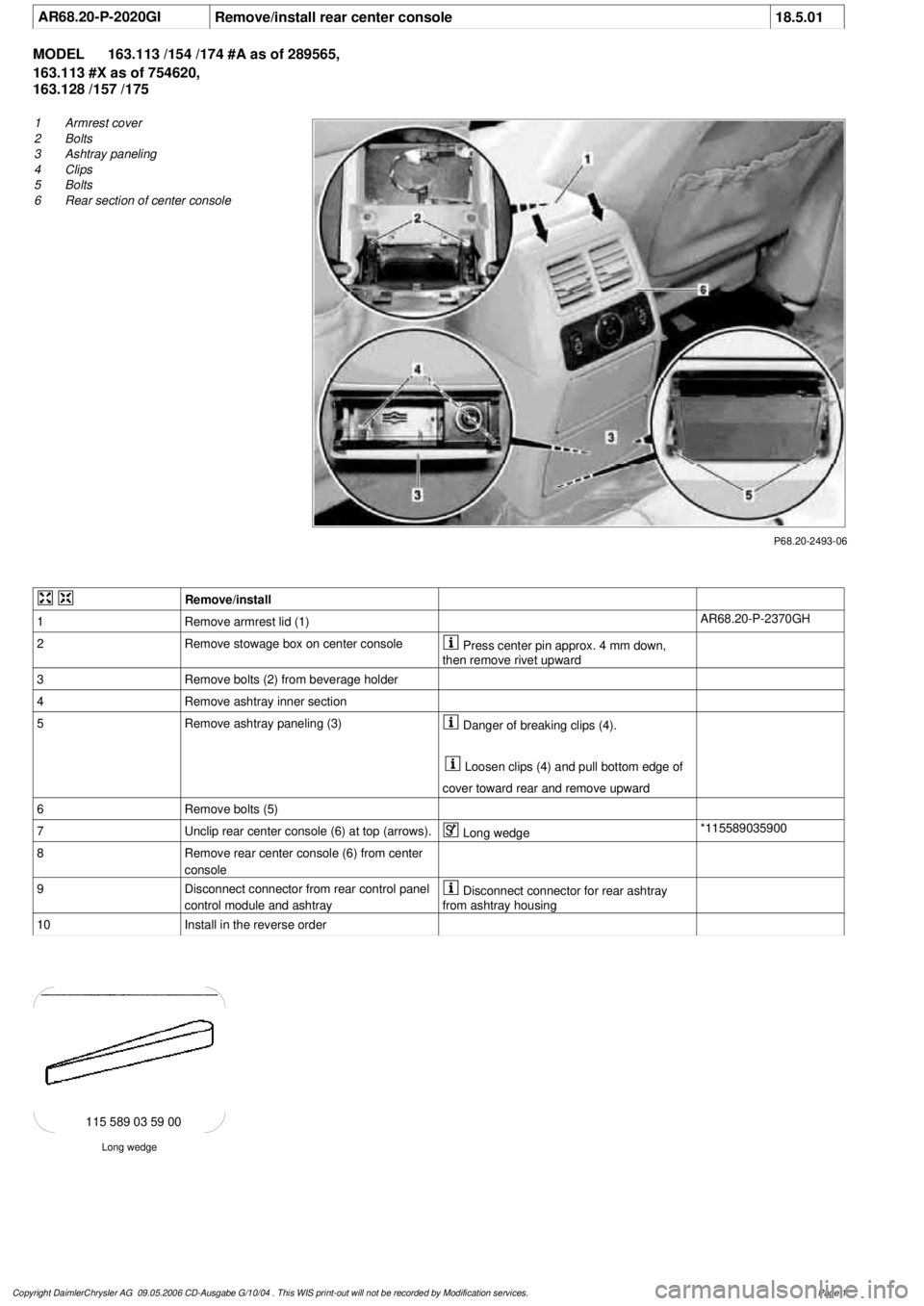
AR68.20-P-2020GI
Remove/install rear center console
18.5.01
MODEL
163.113 /154 /174 #A as of 289565,
163.113 #X as of 754620,
163.128 /157 /175
P68.20-2493-06
1
Armrest cover
2
Bolts
3
Ashtray paneling
4
Clips
5
Bolts
6
Rear section of center console
Remove/install
1
Remove armrest lid (1)
AR68.20-P-2370GH
2
Remove stowage box on center console
Press center pin approx. 4 mm down,
then remove rivet upward
3
Remove bolts (2) from beverage holder
4
Remove ashtray inner section
5
Remove ashtray paneling (3)
Danger of breaking clips (4).
Loosen clips (4) and pull bottom edge of
cover toward rear and remove upward
6
Remove bolts (5)
7
Unclip rear center console (6) at top (arrows).
Long wedge
*115589035900
8
Remove rear center console (6) from center
console
9
Disconnect connector from rear control panel
control module and ashtray
Disconnect connector for rear ashtray
from ashtray housing
10
Install in the reverse order
Long wedge
115 589 03 59 00
Copyright DaimlerChrysler AG 09.05.2006 CD-Ausgabe G/10/04 . This WIS print-out will not be recorde
d by Modification services.
Page 1
Page 2020 of 4133
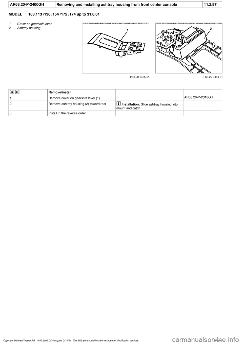
AR68.20-P-2400GH
Removing and installing ashtray housing from front center console
11.2.97
MODEL
163.113 /136 /154 /172 /174 up to 31.8.01
P68.20-0455-01
1
Cover on gearshift lever
2
Ashtray housing
P68.20-0454-01
Remove/install
1
Remove cover on gearshift lever (1)
AR68.20-P-2310GH
2
Remove ashtray housing (2) toward rear
Installation:
Slide ashtray housing into
mount and catch.
3
Install in the reverse order
Copyright DaimlerChrysler AG 10.05.2006 CD-Ausgabe G/10/04 . This WIS print-out will not be recorde
d by Modification services.
Page 1
Page 2023 of 4133
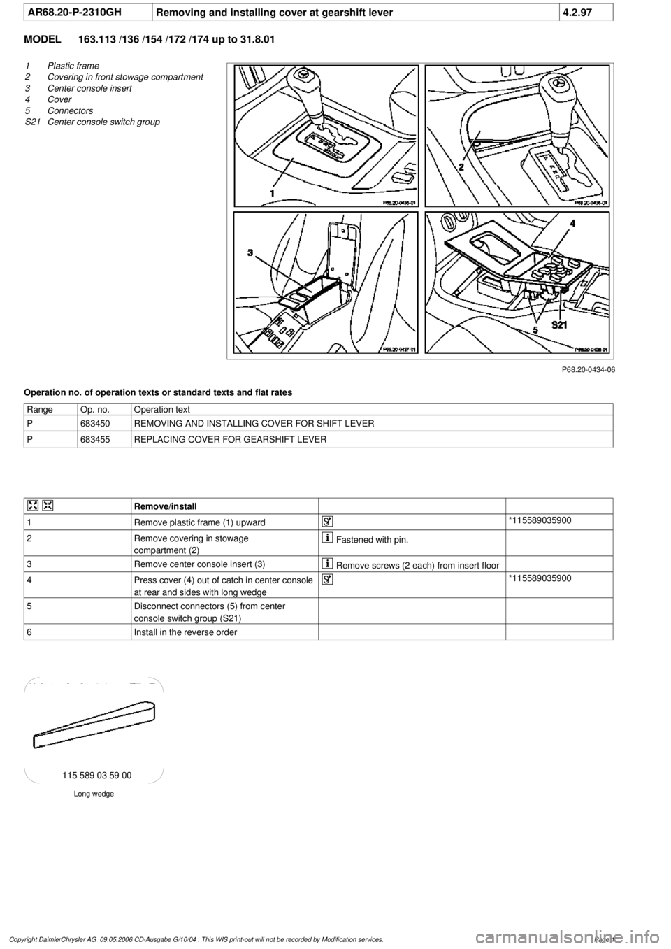
AR68.20-P-2310GH
Removing and installing cover at gearshift lever
4.2.97
MODEL
163.113 /136 /154 /172 /174 up to 31.8.01
P68.20-0434-06
1
Plastic frame
2
Covering in front stowage compartment
3
Center console insert
4
Cover
5
Connectors
S21
Center console switch group
Operation no. of operation texts or standard texts and flat rates
Range
Op. no.
Operation text
P
683450
REMOVING AND INSTALLING COVER FOR SHIFT LEVER
P
683455
REPLACING COVER FOR GEARSHIFT LEVER
Remove/install
1
Remove plastic frame (1) upward
*115589035900
2
Remove covering in stowage
compartment (2)
Fastened with pin.
3
Remove center console insert (3)
Remove screws (2 each) from insert floor
4
Press cover (4) out of catch in center console
at rear and sides with long wedge
*115589035900
5
Disconnect connectors (5) from center
console switch group (S21)
6
Install in the reverse order
Long wedge
115 589 03 59 00
Copyright DaimlerChrysler AG 09.05.2006 CD-Ausgabe G/10/04 . This WIS print-out will not be recorde
d by Modification services.
Page 1
Page 2024 of 4133
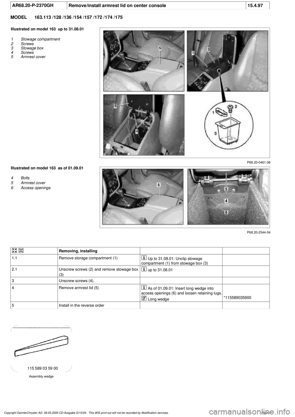
AR68.20-P-2370GH
Remove/install armrest lid on center console
15.4.97
MODEL
163.113 /128 /136 /154 /157 /172 /174 /175
P68.20-0461-06
Illustrated on model 163 up to 31.08.01
1
Stowage compartment
2
Screws
3
Stowage box
4
Screws
5
Armrest cover
P68.20-2544-04
Illustrated on model 163 as of 01.09.01
4
Bolts
5
Armrest cover
6
Access openings
Removing, installing
1.1
Remove storage compartment (1)
Up to 31.08.01: Unclip stowage
compartment (1) from stowage box (3)
2.1
Unscrew screws (2) and remove stowage box
(3)
up to 31.08.01
3
Unscrew screws (4).
4
Remove armrest lid (5)
As of 01.09.01: Insert long wedge into
access openings (6) and loosen retaining lugs.
Long wedge
*115589035900
5
Install in the reverse order
Assembly wedge
115 589 03 59 00
Copyright DaimlerChrysler AG 09.05.2006 CD-Ausgabe G/10/04 . This WIS print-out will not be recorde
d by Modification services.
Page 1
Page 2057 of 4133
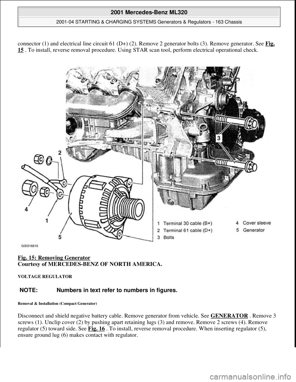
connector (1) and electrical line circuit 61 (D+) (2). Remove 2 generator bolts (3). Remove generator. See Fig.
15 . To install, reverse removal procedure. Using STAR scan tool, perform electrical operational check.
Fig. 15: Removing Generator
Courtesy of MERCEDES-BENZ OF NORTH AMERICA.
VOLTAGE REGULATOR
Removal & Installation (Compact Generator)
Disconnect and shield negative battery cable. Remove generator from vehicle. See GENERATOR . Remove 3
screws (1). Unclip cover (2) by pushing apart retaining lugs (3) and remove. Remove 2 screws (4). Remove
regulator (5) toward side. See Fig. 16
. To install, reverse removal procedure. When inserting regulator (5),
ensure
ground lug (6) makes contact with regulator.
NOTE: Numbers in text refer to numbers in figures.
2001 Mercedes-Benz ML320
2001-04 STARTING & CHARGING SYSTEMS Generators & Regulators - 163 Chassis
me
Saturday, October 02, 2010 3:20:32 PMPage 23 © 2006 Mitchell Repair Information Company, LLC.
Page 2078 of 4133
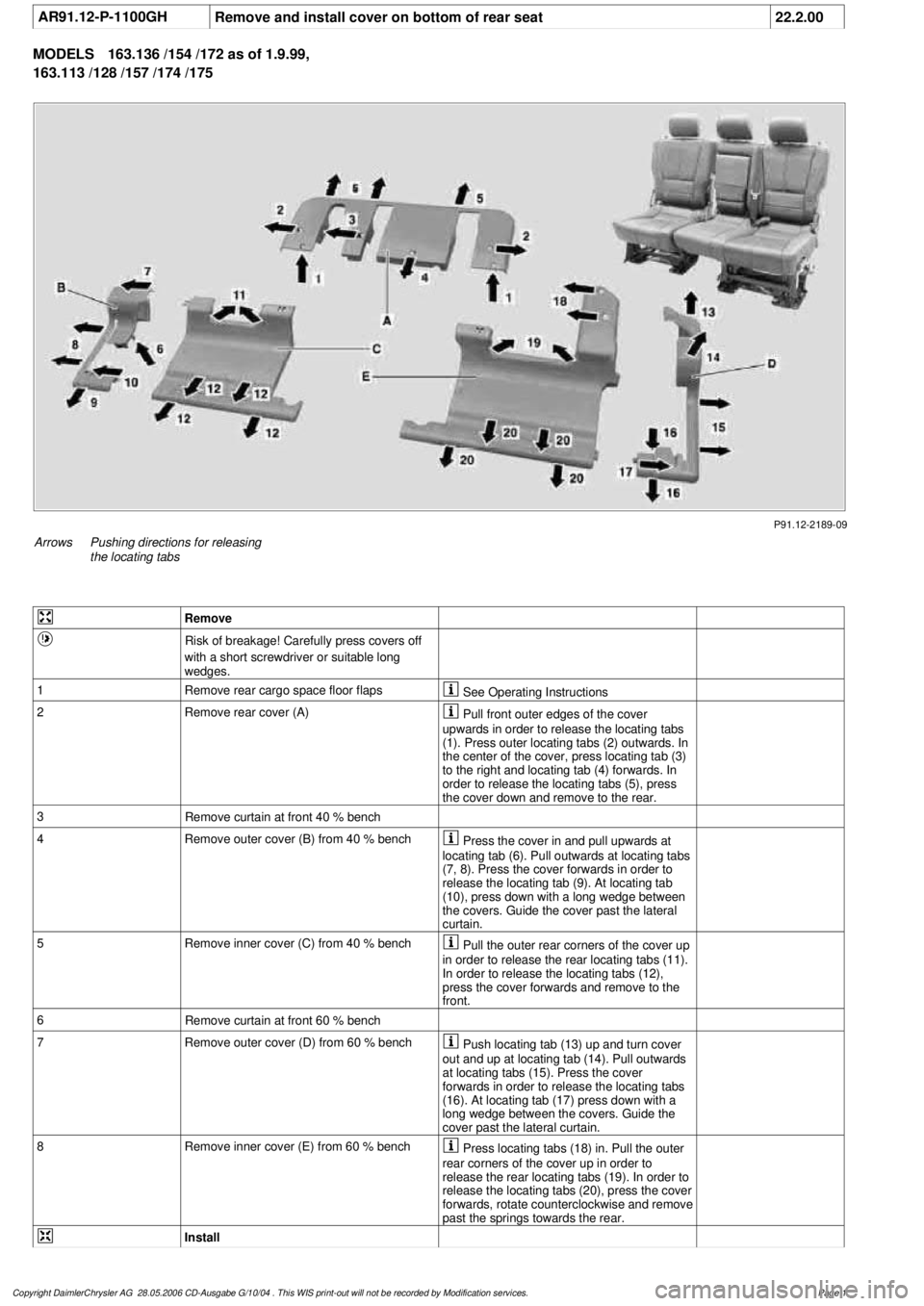
AR91.12-P-1100GH
Remove and install cover on bottom of rear seat
22.2.00
MODELS
163.136 /154 /172 as of 1.9.99,
163.113 /128 /157 /174 /175
P91.12-2189-09
Arrows
Pushing directions for releasing
the locating tabs
Remove
Risk of breakage! Carefully press covers off
with a short screwdriver or suitable long
wedges.
1
Remove rear cargo space floor flaps
See Operating Instructions
2Remove rear cover (A)
Pull front outer edges of the cover
upwards in order to release the locating tabs
(1). Press outer locating tabs (2) outwards. In
the center of the cover, press locating tab (3)
to the right and locating tab (4) forwards. In
order to release the locating tabs (5), press
the cover down and remove to the rear.
3
Remove curtain at front 40 % bench
4
Remove outer cover (B) from 40 % bench
Press the cover in and pull upwards at
locating tab (6). Pull outwards at locating tabs
(7, 8). Press the cover forwards in order to
release the locating tab (9). At locating tab
(10), press down with a long wedge between
the covers. Guide the cover past the lateral
curtain.
5
Remove inner cover (C) from 40 % bench
Pull the outer rear corners of the cover up
in order to release the rear locating tabs (11).
In order to release the locating tabs (12),
press the cover forwards and remove to the
front.
6
Remove curtain at front 60 % bench
7
Remove outer cover (D) from 60 % bench
Push locating tab (13) up and turn cover
out and up at locating tab (14). Pull outwards
at locating tabs (15). Press the cover
forwards in order to release the locating tabs
(16). At locating tab (17) press down with a
long wedge between the covers. Guide the
cover past the lateral curtain.
8
Remove inner cover (E) from 60 % bench
Press locating tabs (18) in. Pull the outer
rear corners of the cover up in order to
release the rear locating tabs (19). In order to
release the locating tabs (20), press the cover
forwards, rotate counterclockwise and remove
past the springs towards the rear.
Install
Copyright DaimlerChrysler AG 28.05.2006 CD-Ausgabe G/10/04 . This WIS print-out will not be recorde
d by Modification services.
Page 1
Page 2080 of 4133
Crankshaft Position Sensor DIY
hopefully this will help others with what appears to be a common stalling issue in the ML series.
Location:
--------
It's on the rear of the engine where the engine mates with the tranny on the driver's side. There are 2
types. Be sure to get the correct one
Here it is:
1) Get
CPS
at dealer, its a VIN specific part. $125 from my local stealer.
2) Tools needed: Socket screwdriver, Good lighting (portable) shop lights, size 8 outside torx socket,
maybe a ratche
t and extentions depending on your flexibility, magnetic part retrieval tool (skip this at
your peril), bath towel, and long sleeve shirt, step stool, blue thread locker (optional)
3) Open hood and remove engine cover, it just pulls off and on
4) Set wor
k light(s) toward back of engine, lighting behind drivers cylinder head
5) Set bath towel on front of ML to kneel on of your knees will die, wearing long sleeve shirt or your
wrists will be cut.
6) Climb up on towel and look behind engine from above and
right (see .jpg), finding torx attachment
holding your
CPS
.
7) Remove torx screw and pull out
CPS
, disconnect one way connector (wiring)
8) Replace with new (leaving wire detached for now)
9) This is the hardest step by far, and requires patience and fl exibility. Apply some thread locker and
insert screw and start the threads. Tighten with torx on socket screwdriver. This step took about 1/2
hour and numerous dropped screws and retrievals with mag tool.
10) Attach wiring to
CPS
11) Reinstall engine cov
er
12) Clean up tools, towel and lights and everything
13) Drink beer and toast yourself for saving yourself at least $100 and a day of your time dropping off
and picking up cars at shop
Hope this helps someone in the community.
Dickie
00 ML 32
0
Page 2088 of 4133

16
Remove poly V-belt (8)
Installation:
Lock tensioning device with
a drift or pin (diameter 5 mm).
Model 163.154 /157 /172.
AR13.22-P-1202B
Model 163.174 /175.
AR13.22-P-1202BA
17
Detach the coolant line (16) at the cylinder
head on the left
6 mm socket hexagon
*WH58.30-Z-1001-06A
7 mm socket hexagon
*WH58.30-Z-1002-06A
18.1
Remove fender liner (9)
Only with engine 113.113.942 /965 / 981.
AR88.10-P-1300GH
19.1
Remove shield (10)
Only with engine 113.942 /965 /981.
20.1
Remove exhaust bracket (11)
Only with engine 113.942 /965 /981.
Support exhaust system.
21
Detach exhaust system at exhaust manifold
Installation:
On vehicles with engine
damage, the exhaust system must be
examined for swarfs before assembling and
any swarfs present must be removed, in order
to avoid consequential damage.
*BA14.10-P-1002-01B
22
Position crankshaft to 40° after ignition TDC
on cylinder 1
The engine must not be turned back;
otherwise the timing chain can get jammed.
AR05.10-P-6858V
Rotate engine at the crankshaft in running
direction until scribe mark 40° on pulley/
vibration damper corresponds with scribe
mark on timing case.
The grooves on the camshafts must be
pointing toward the inner V.
23
Lock camshafts with locating plates
Locating plate
*112589003200
Locating plate
*112589013200
24
Remove chain tensioner (17)
Model 163.154 /157 with engine 112.942/
970, model 163.172 with engine 113.942.
AR05.10-P-7800C
Model 163.174 /175 with engine 113.981/ 965.
AR05.10-P-7800CA
25.1
Remove oil filter housing (18) together with oil-
water heat exchanger
Engine 113.942.
AR18.20-P-3471B
Engine 112.942/970.
AR18.20-P-3471BA
26
Unscrew camshaft sprockets (19)
If camshaft sprockets are removed,
engine must no longer be cranked, otherwise
timing chain might jam.
Engine 113.942 /965 /981:
#
Tie timing chain tight on both camshaft
sprockets with tie straps.
Engine 112.942 /970:
#
Right-hand camshaft sprocket:
Tie timing chain tight on camshaft sprocket
with tie strap.
Left-hand camshaft sprocket:
Mark camshaft sprocket to timing chain and
remove camshaft sprocket.
It is not possible for the timing chain to
jump across at the crankshaft and balancing
shaft.
After installation:
#
Inspect basic position of camshafts.
AR05.10-P-6858V
If necessary after checking:
#
Set the basic position of camshafts
AR05.20-P-6020AU
Open-end wrench
*112589000100
Insertion tool
*112589010300
Torque wrench
*001589722100
*BA05.20-P-1001-01B
27
Remove camshaft bearing bridges (28)
Pay attention to slackening and tightening
pattern!
AR05.20-P-7103AU
28
Unscrew bolts, cylinder head
!
timing case
cover (20)
*BA01.40-P-1002-01C
Copyright DaimlerChrysler AG 20.05.2006 CD-Ausgabe G/10/04 . This WIS print-out will not be recorde
d by Modification services.
Page 4