1997 MERCEDES-BENZ ML430 battery
[x] Cancel search: batteryPage 2883 of 4133
![MERCEDES-BENZ ML430 1997 Complete Repair Manual MODELS 124, 129, 140, 163 up to 30.11.99, 163 as of 1.9.01, 168, 170, 201, 202, 208, 210, 215, 220
EXPLANATION OF SYMBOLS FOR TESTERS AND COMPONENTS - AD00.00-P-2000-01A
0.0 [] 1Key to diagnostics
s MERCEDES-BENZ ML430 1997 Complete Repair Manual MODELS 124, 129, 140, 163 up to 30.11.99, 163 as of 1.9.01, 168, 170, 201, 202, 208, 210, 215, 220
EXPLANATION OF SYMBOLS FOR TESTERS AND COMPONENTS - AD00.00-P-2000-01A
0.0 [] 1Key to diagnostics
s](/manual-img/4/57307/w960_57307-2882.png)
MODELS 124, 129, 140, 163 up to 30.11.99, 163 as of 1.9.01, 168, 170, 201, 202, 208, 210, 215, 220
EXPLANATION OF SYMBOLS FOR TESTERS AND COMPONENTS - AD00.00-P-2000-01A
0.0 [] 1Key to diagnostics
symbols AD00.00-P-2001A
0.0 [] 2Diagnosis assignmentexcept models 215, 220AD00.00-P-2002A
0.0 [] 3Connect test equipment
diagnosisexcept model 215AD00.00-P-2003A
0.0 [] 4Diagnostic procedureonly for vehicle systems
that can be diagnosed using
STAR DIAGNOSISAD00.00-P-2004A
DescriptionLogoDescriptionLogoDescriptionLogo
ABS Adapter Battery Short-circuit
35-pin socket
box Direct current
generator Short-circuit to
ground
126-pin socket
box Direct current
motor Open-circuit
Function
generator Capacitor Multimeter
alternating
voltage type of
measurement
Hand-Held
Tester Coil Multimeter
resistance type of
measurement
Pulse counter Resistance Function
generator square-
wave signal shape
Lambda control
tester Ground Function
generator
sinusoidal signal
shape
Pressure gauge In order Oscilloscope
Multimeter Fault Adapter cable
with light-
emitting diode
Decade resistor Greater than > Multimeter direct
current type of
measurement
Bridge Less than < Multimeter
alternating
current type of
measurement
2004 Mercedes-Benz ML350
1998-2005 GENINFO Overall vehicle - 163 Chassis
me
Saturday, October 02, 2010 3:47:48 PMPage 238 © 2006 Mitchell Repair Information Company, LLC.
Page 3050 of 4133
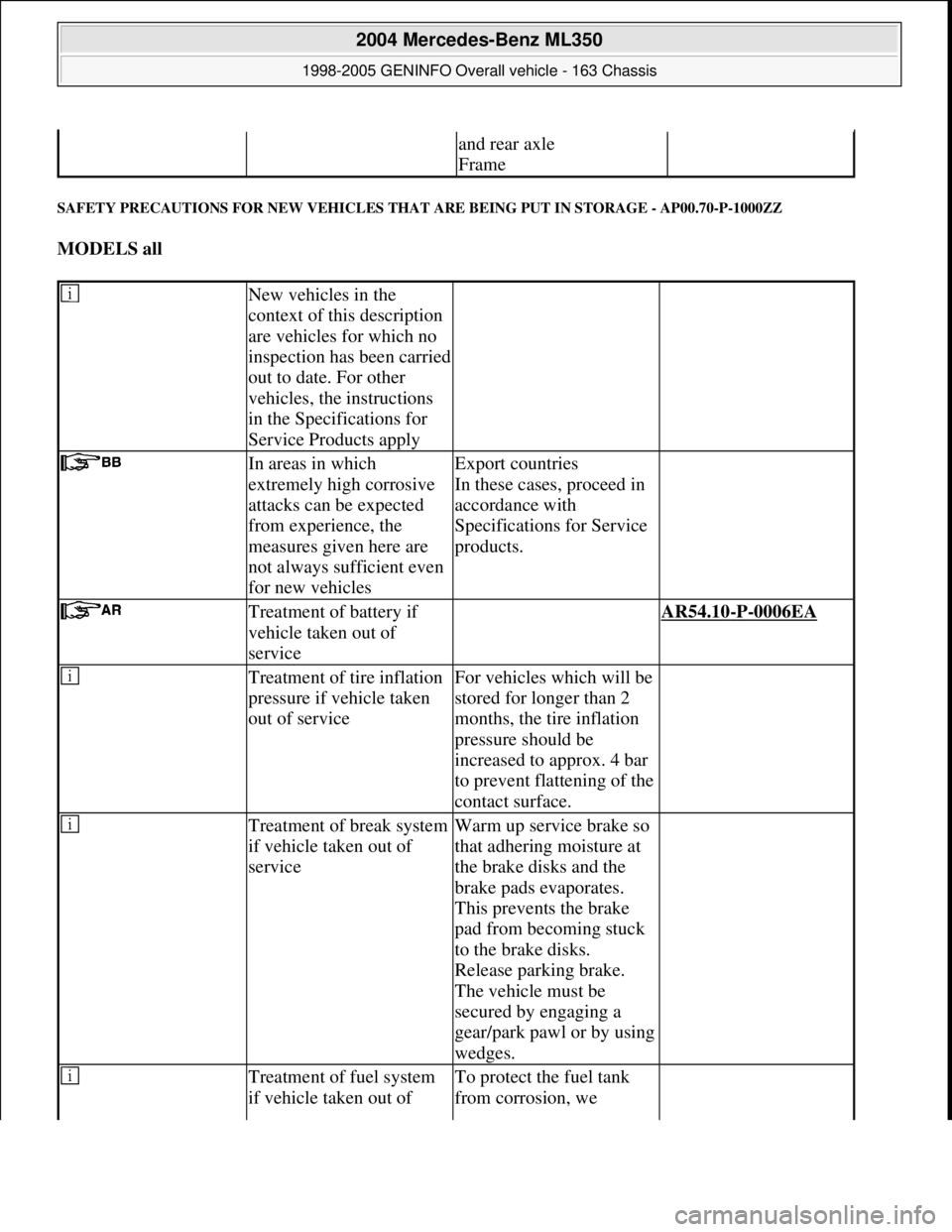
SAFETY PRECAUTIONS FOR NEW VEHICLES THAT ARE BEING PUT IN STORAGE - AP00.70-P-1000ZZ
MODELS all
and rear axle
Frame
New vehicles in the
context of this description
are vehicles for which no
inspection has been carried
out to date. For other
vehicles, the instructions
in the Specifications for
Service Products apply
In areas in which
extremely high corrosive
attacks can be expected
from experience, the
measures given here are
not always sufficient even
for new vehiclesExport countries
In these cases, proceed in
accordance with
Specifications for Service
products.
Treatment of battery if
vehicle taken out of
service AR54.10-P-0006EA
Treatment of tire inflation
pressure if vehicle taken
out of serviceFor vehicles which will be
stored for longer than 2
months, the tire inflation
pressure should be
increased to approx. 4 bar
to prevent flattening of the
contact surface.
Treatment of break system
if vehicle taken out of
serviceWarm up service brake so
that adhering moisture at
the brake disks and the
brake pads evaporates.
This prevents the brake
pad from becoming stuck
to the brake disks.
Release parking brake.
The vehicle must be
secured by engaging a
gear/park pawl or by using
wedges.
Treatment of fuel system
if vehicle taken out of To protect the fuel tank
from corrosion, we
2004 Mercedes-Benz ML350
1998-2005 GENINFO Overall vehicle - 163 Chassis
me
Saturday, October 02, 2010 3:47:52 PMPage 405 © 2006 Mitchell Repair Information Company, LLC.
Page 3051 of 4133
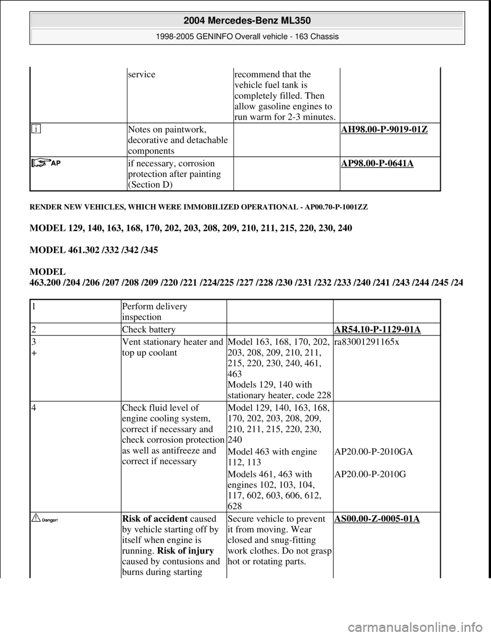
RENDER NEW VEHICLES, WHICH WERE IMMOBILIZED OPERATIONAL - AP00.70-P-1001ZZ
MODEL 129, 140, 163, 168, 170, 202, 203, 208, 209, 210, 211, 215, 220, 230, 240
MODEL 461.302 /332 /342 /345
MODEL
463.200 /204 /206 /207 /208 /209 /220 /221 /224/225 /227 /228 /230 /231 /232 /233 /240 /241 /243 /244 /245 /2
4
servicerecommend that the
vehicle fuel tank is
completely filled. Then
allow gasoline engines to
run warm for 2-3 minutes.
Notes on paintwork,
decorative and detachable
components AH98.00-P-9019-01Z
if necessary, corrosion
protection after painting
(Section D) AP98.00-P-0641A
1Perform delivery
inspection
2Check battery AR54.10-P-1129-01A
3
+Vent stationary heater and
top up coolantModel 163, 168, 170, 202,
203, 208, 209, 210, 211,
215, 220, 230, 240, 461,
463
Models 129, 140 with
stationary heater, code 228ra83001291165x
4Check fluid level of
engine cooling system,
correct if necessary and
check corrosion protection
as well as antifreeze and
correct if necessaryModel 129, 140, 163, 168,
170, 202, 203, 208, 209,
210, 211, 215, 220, 230,
240
Model 463 with engine
112, 113AP20.00-P-2010GA
Models 461, 463 with
engines 102, 103, 104,
117, 602, 603, 606, 612,
628AP20.00-P-2010G
Risk of accident caused
by vehicle starting off by
itself when engine is
running. Risk of injury
caused by contusions and
burns during starting Secure vehicle to prevent
it from moving. Wear
closed and snug-fitting
work clothes. Do not grasp
hot or rotating parts.AS00.00-Z-0005-01A
2004 Mercedes-Benz ML350
1998-2005 GENINFO Overall vehicle - 163 Chassis
me
Saturday, October 02, 2010 3:47:52 PMPage 406 © 2006 Mitchell Repair Information Company, LLC.
Page 3185 of 4133

AD54.30-P-2000-02GC
Notes on HHT previous knowledge diagnosis
IC
HHT :
The instrument cluster and active service system (ASSYST) sub-
function are checked with HHT, there being the choice of the
following functions for this:
1. Control module version
2. Fault memory
3. Actual values
4. Actuations
5. Control module adaptation
Additional information on test items 2, 3 and 5 can be called up using
the INPUT key
Control module adaptation
The following alternatives are available in the HHT under control
module adaptation:
1.)
Read out coding and transfer to new instrument cluster. IC and
ASSYST.
2.)
Read out/change codings e.g.:
Engine and national variants,
version of fuel tank,
special equipment etc.
3.)
Settings:
1
Clock
2
Put forward kilometer reading
3
Put back kilometer reading
4
Oil change
5
Reset oil change initiated inadvertently
6
Active Service System
7
Enter times with battery disconnected
8
Set minimum oil warning
Before replacing a defective instrument cluster, readout the existing
variant codings (driving data and instrument cluster data) and store in
the HHT on an interim basis. Read in the values stored on an interim
basis again after installing the new instrument cluster.
If it is not possible to read out the stored variant coding, all variant
codings must be input manually (menu-assistance in HHT).
When installing an instrument cluster on an experimental basis, do
not put forward the kilometer reading as it cannot be put back later.
Copyright DaimlerChrysler AG 05.06.2006 CD-Ausgabe G/10/04 . This WIS print-out will not be recorde
d by Modification services.
Page 1
Page 3201 of 4133
Danger!
Risk of explosion
from explosive gas.
Risk
of poisoning and caustic burns from
swallowing battery electrolyte.
Risk of injury
through burns to skin and eyes from battery
acid or when handling damaged lead-acid
batteries
No fire, sparks, naked flames or smoking.
Wear protective gloves, acid-resistant
clothing and safety glasses. Pour battery
electrolyte only into suitable and appropriately
marked containers.
AS54.10-Z-0001-01A
4
Remove battery
AR54.10-P-0005GH
5
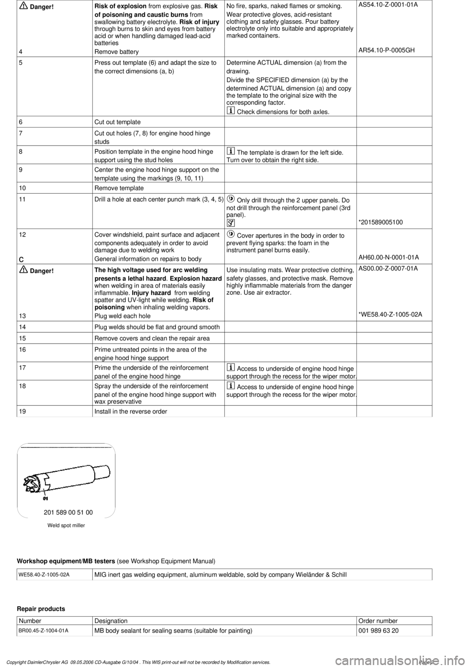
Press out template (6) and adapt the size to
the correct dimensions (a, b)Determine ACTUAL dimension (a) from the
drawing.
Divide the SPECIFIED dimension (a) by the
determined ACTUAL dimension (a) and copy
the template to the original size with the
corresponding factor.
Check dimensions for both axles.
6
Cut out template
7
Cut out holes (7, 8) for engine hood hinge
studs
8
Position template in the engine hood hinge
support using the stud holes
The template is drawn for the left side.
Turn over to obtain the right side.
9
Center the engine hood hinge support on the
template using the markings (9, 10, 11)
10
Remove template
11
Drill a hole at each center punch mark (3, 4, 5)
Only drill through the 2 upper panels. Do
not drill through the reinforcement panel (3rd
panel).
*201589005100
12
Cover windshield, paint surface and adjacent
components adequately in order to avoid
damage due to welding work
Cover apertures in the body in order to
prevent flying sparks: the foam in the
instrument panel burns easily.
c
General information on repairs to body
AH60.00-N-0001-01A
Danger!
The high voltage used for arc welding
presents a lethal hazard
.
Explosion hazard
when welding in area of materials easily
inflammable.
Injury hazard
from welding
spatter and UV-light while welding.
Risk of
poisoning
when inhaling welding vapors.
Use insulating mats. Wear protective clothing,
safety glasses, and protective mask.
Remove
highly inflammable materials from the danger
zone. Use air extractor.
AS00.00-Z-0007-01A
13
Plug weld each hole
*WE58.40-Z-1005-02A
14
Plug welds should be flat and ground smooth
15
Remove covers and clean the repair area
16
Prime untreated points in the area of the
engine hood hinge support
17
Prime the underside of the reinforcement
panel of the engine hood hinge
Access to underside of engine hood hinge
support through the recess for the wiper motor.
18
Spray the underside of the reinforcement
panel of the engine hood hinge support with
wax preservative
Access to underside of engine hood hinge
support through the recess for the wiper motor.
19
Install in the reverse order
Weld spot miller
201 589 00 51 00
Workshop equipment/MB testers
(see Workshop Equipment Manual)
WE58.40-Z-1005-02A
MIG inert gas welding equipment, aluminum weldable, sold by company Wieländer & Schill
Repair products
Number
Designation
Order number
BR00.45-Z-1004-01A
MB body sealant for sealing seams (suitable for painting)
001 989 63 20
Copyright DaimlerChrysler AG 09.05.2006 CD-Ausgabe G/10/04 . This WIS print-out will not be recorde
d by Modification services.
Page 2
Page 3204 of 4133

3
Remove engine hood hinge on the front
passenger side
AR88.40-P-3060GH
*BR00.45-Z-1004-01A
Danger!
Risk of explosion
from explosive gas.
Risk
of poisoning and caustic burns from
swallowing battery electrolyte.
Risk of injury
through burns to skin and eyes from battery
acid or when handling damaged lead-acid
batteries
No fire, sparks, naked flames or smoking.
Wear protective gloves, acid-resistant
clothing and safety glasses. Pour battery
electrolyte only into suitable and appropriately
marked containers.
AS54.10-Z-0001-01A
4
Remove battery
AR54.10-P-0005GH
5
Remove air conditioning blower motor
AR83.30-P-5560GH
6
Print out template (6) and adapt the size to
the correct dimensions (a, b)Determine ACTUAL dimension (a) from the
drawing.
Divide the SPECIFIED dimension (a) by the
determined ACTUAL dimension (a) and copy
the template to the original size with the
corresponding factor.
Check dimensions for both axles.
7
Cut out template
8
Cut out holes (7, 8) for engine hood hinge
studs
9
Position template in the engine hood hinge
support using the stud holes
The template is drawn for the left side.
Turn over to obtain the right side.
10
Center the engine hood hinge support on the
template using the markings (9, 10, 11)
11
Remove template
12
Drill a hole at each center punch mark (3, 4, 5)
Only drill through the 2 upper panels. Do
not drill through the reinforcement panel (3rd
panel).
*201589005100
13
Cover windshield, paint surface and adjacent
components adequately in order to avoid
damage due to welding work
Cover apertures in the body in order to
prevent flying sparks: the foam in the
instrument panel burns easily.
c
General information on repairs to body
AH60.00-N-0001-01A
Danger!
The high voltage used for arc welding
presents a lethal hazard
.
Explosion hazard
when welding in area of materials easily
inflammable.
Injury hazard
from welding
spatter and UV-light while welding.
Risk of
poisoning
when inhaling welding vapors.
Use insulating mats. Wear protective clothing,
safety glasses, and protective mask.
Remove
highly inflammable materials from the danger
zone. Use air extractor.
AS00.00-Z-0007-01A
14
Plug weld each hole
*WE58.40-Z-1005-02A
15
Plug welds should be flat and ground smooth
16
Remove covers and clean the repair area
17
Prime untreated points in the area of the
engine hood hinge support
18
Prime the underside of the reinforcement
panel of the engine hood hinge
Access to underside of engine hood hinge
support through the recess for the wiper motor.
19
Spray the underside of the reinforcement
panel of the engine hood hinge support with
wax preservative
Access to underside of engine hood hinge
support through the recess for the wiper motor.
20
Install in the reverse order
Weld spot miller
201 589 00 51 00
Workshop equipment/MB testers
(see Workshop Equipment Manual)
WE58.40-Z-1005-02A
MIG inert gas welding equipment, aluminum weldable, sold by company Wieländer & Schill
Repair products
Copyright DaimlerChrysler AG 09.05.2006 CD-Ausgabe G/10/04 . This WIS print-out will not be recorde
d by Modification services.
Page 2
Page 3217 of 4133
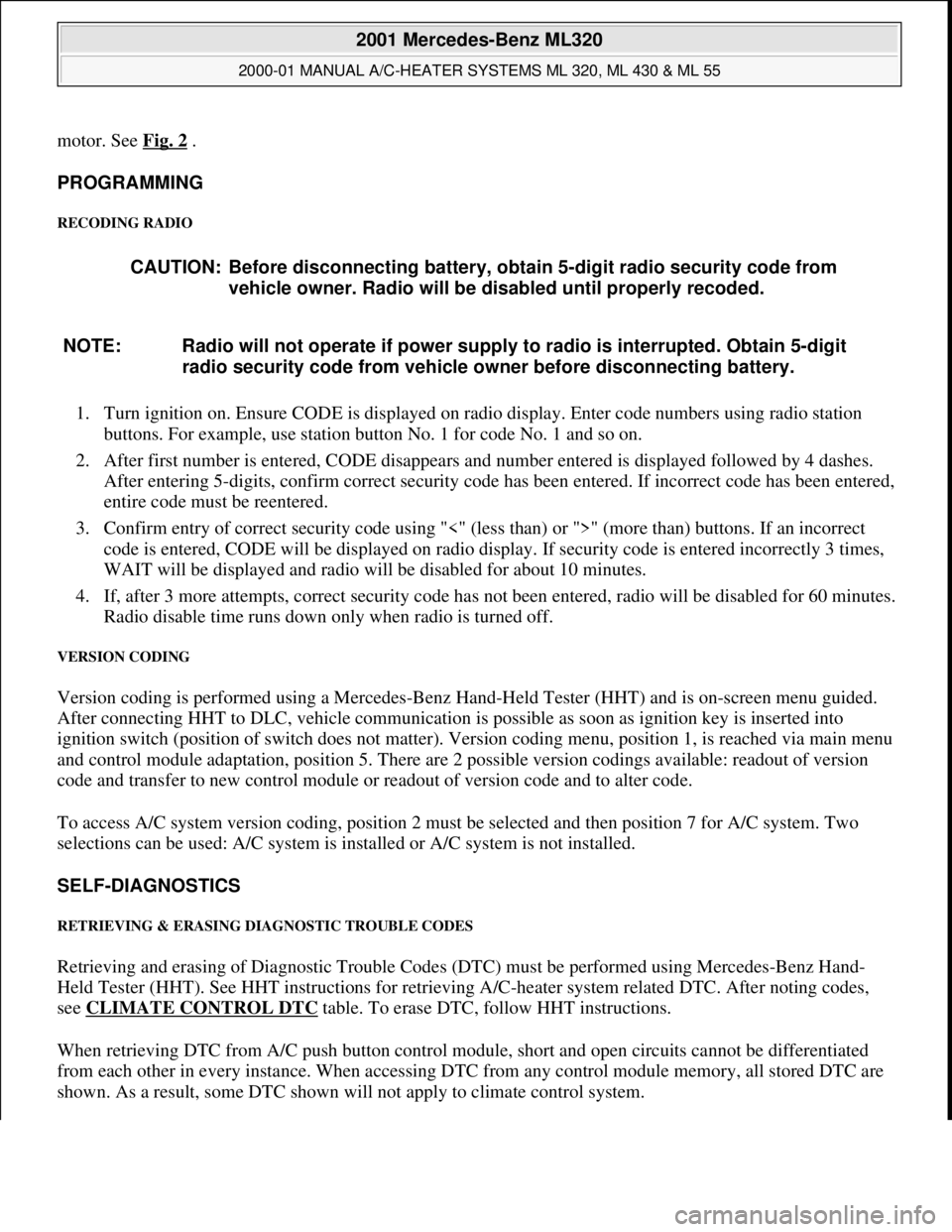
motor. See Fig. 2 .
PROGRAMMING
RECODING RADIO
1. Turn ignition on. Ensure CODE is displayed on radio display. Enter code numbers using radio station
buttons. For example, use station button No. 1 for code No. 1 and so on.
2. After first number is entered, CODE disappears and number entered is displayed followed by 4 dashes.
After entering 5-digits, confirm correct security code has been entered. If incorrect code has been entered,
entire code must be reentered.
3. Confirm entry of correct security code using "<" (less than) or ">" (more than) buttons. If an incorrect
code is entered, CODE will be displayed on radio display. If security code is entered incorrectly 3 times,
WAIT will be displayed and radio will be disabled for about 10 minutes.
4. If, after 3 more attempts, correct security code has not been entered, radio will be disabled for 60 minutes.
Radio disable time runs down only when radio is turned off.
VERSION CODING
Version coding is performed using a Mercedes-Benz Hand-Held Tester (HHT) and is on-screen menu guided.
After connecting HHT to DLC, vehicle communication is possible as soon as ignition key is inserted into
ignition switch (position of switch does not matter). Version coding menu, position 1, is reached via main menu
and control module adaptation, position 5. There are 2 possible version codings available: readout of version
code and transfer to new control module or readout of version code and to alter code.
To access A/C system version coding, position 2 must be selected and then position 7 for A/C system. Two
selections can be used: A/C system is installed or A/C system is not installed.
SELF-DIAGNOSTICS
RETRIEVING & ERASING DIAGNOSTIC TROUBLE CODES
Retrieving and erasing of Diagnostic Trouble Codes (DTC) must be performed using Mercedes-Benz Hand-
Held Tester (HHT). See HHT instructions for retrieving A/C-heater system related DTC. After noting codes,
see CLIMATE CONTROL DTC
table. To erase DTC, follow HHT instructions.
When retrieving DTC from A/C push button control module, short and open circuits cannot be differentiated
from each other in every instance. When accessing DTC from any control module memory, all stored DTC are
shown. As a result, some DTC shown will not appl
y to climate control system. CAUTION: Before disconnecting battery, obtain 5-digit radio security code from
vehicle owner. Radio will be disabled until properly recoded.
NOTE: Radio will not operate if power supply to radio is interrupted. Obtain 5-digit
radio security code from vehicle owner before disconnecting battery.
2001 Mercedes-Benz ML320
2000-01 MANUAL A/C-HEATER SYSTEMS ML 320, ML 430 & ML 55
me
Saturday, October 02, 2010 3:25:10 PMPage 6 © 2006 Mitchell Repair Information Company, LLC.
Page 3225 of 4133
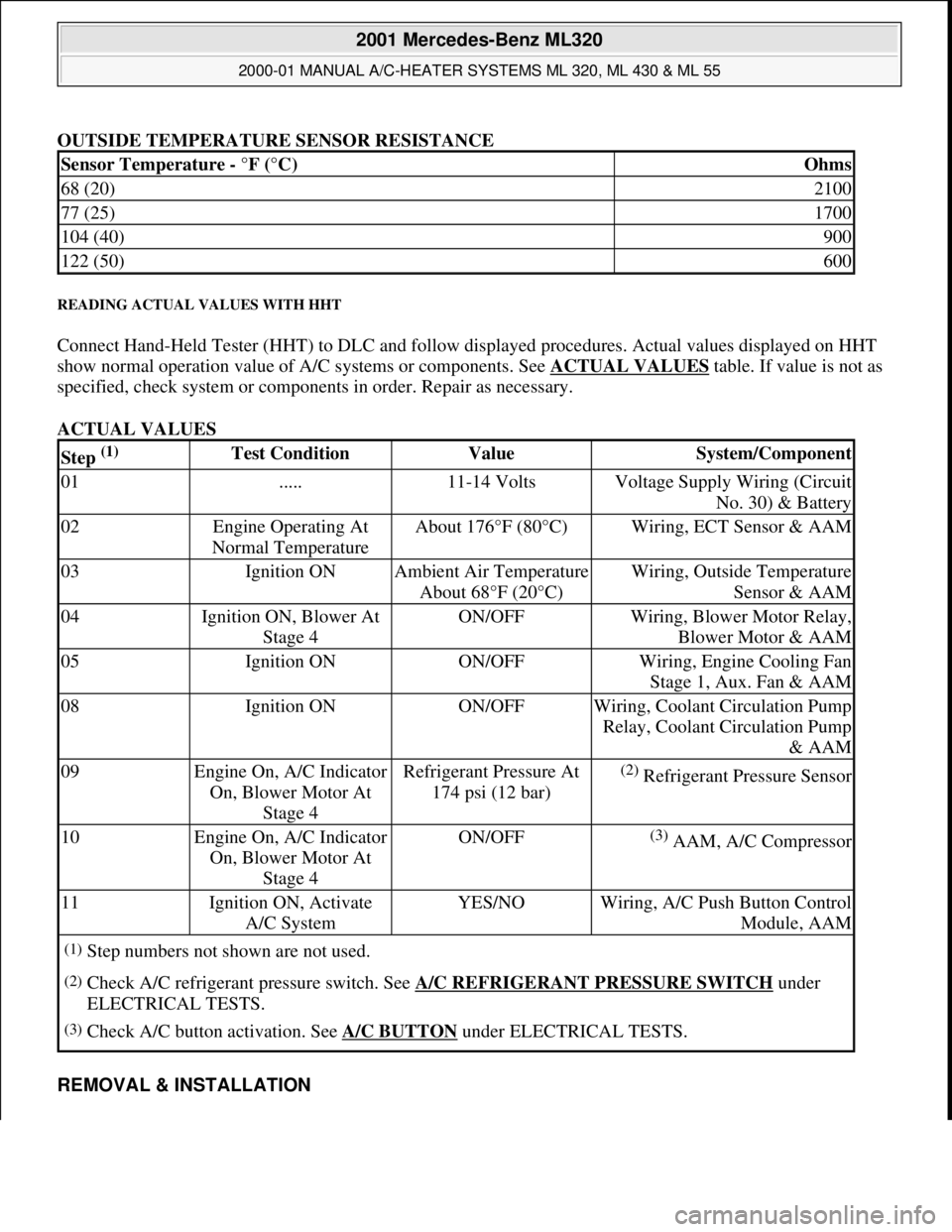
OUTSIDE TEMPERATURE SENSOR RESISTANCE
READING ACTUAL VALUES WITH HHT
Connect Hand-Held Tester (HHT) to DLC and follow displayed procedures. Actual values displayed on HHT
show normal operation value of A/C systems or components. See ACTUAL VALUES
table. If value is not as
specified, check system or components in order. Repair as necessary.
ACTUAL VALUES
REMOVAL & INSTALLATION
Sensor Temperature - °F (°C)Ohms
68 (20)2100
77 (25)1700
104 (40)900
122 (50)600
Step (1) Test ConditionValueSystem/Component
01.....11-14 VoltsVoltage Supply Wiring (Circuit
No. 30) & Battery
02Engine Operating At
Normal TemperatureAbout 176°F (80°C)Wiring, ECT Sensor & AAM
03Ignition ONAmbient Air Temperature
About 68°F (20°C)Wiring, Outside Temperature
Sensor & AAM
04Ignition ON, Blower At
Stage 4ON/OFFWiring, Blower Motor Relay,
Blower Motor & AAM
05Ignition ONON/OFFWiring, Engine Cooling Fan
Stage 1, Aux. Fan & AAM
08Ignition ONON/OFFWiring, Coolant Circulation Pump
Relay, Coolant Circulation Pump
& AAM
09Engine On, A/C Indicator
On, Blower Motor At
Stage 4Refrigerant Pressure At
174 psi (12 bar)(2) Refrigerant Pressure Sensor
10Engine On, A/C Indicator
On, Blower Motor At
Stage 4ON/OFF(3) AAM, A/C Compressor
11Ignition ON, Activate
A/C SystemYES/NOWiring, A/C Push Button Control
Module, AAM
(1)Step numbers not shown are not used.
(2)Check A/C refrigerant pressure switch. See A/C REFRIGERANT PRESSURE SWITCH under
ELECTRICAL TESTS.
(3)Check A/C button activation. See A/C BUTTON under ELECTRICAL TESTS.
2001 Mercedes-Benz ML320
2000-01 MANUAL A/C-HEATER SYSTEMS ML 320, ML 430 & ML 55
me
Saturday, October 02, 2010 3:25:10 PMPage 14 © 2006 Mitchell Repair Information Company, LLC.