Page 2146 of 4133
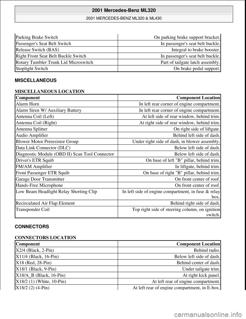
MISCELLANEOUS
MISCELLANEOUS LOCATION
CONNECTORS
CONNECTORS LOCATION
Parking Brake SwitchOn parking brake support bracket.
Passenger's Seat Belt SwitchIn passenger's seat belt buckle.
Release Switch (BAS)Integral to brake booster.
Right Front Seat Belt Buckle SwitchIn passenger's seat belt buckle.
Rotary Tumbler Trunk Lid MicroswitchPart of tailgate latch assembly.
Stoplight SwitchOn brake pedal support.
ComponentComponent Location
Alarm HornIn left rear corner of engine compartment.
Alarm Siren W/ Auxiliary BatteryIn left rear corner of engine compartment.
Antenna Coil (Left)At left side of rear window, behind trim.
Antenna Coil (Right)At right side of rear window, behind trim.
Antenna SplitterOn right side of liftgate.
Audio AmplifierBehind left side of dash.
Blower Motor Preresistor GroupUnder right side of dash, in blower assembly.
Data Link Connector (DLC)Below left side of dash.
Diagnostic Module (OBD II) Scan Tool ConnectorBelow left side of dash.
Driver's ETR SquibOn base of left "B" pillar, behind trim.
FM/AM AmplifierIn liftgate, behind trim.
Front Passenger ETR SquibOn base of right "B" pillar, behind trim.
Garage Door TransmitterOn front center of roof.
Hands-Free MicrophoneOn front center of roof.
Low Beam Headlight Relay Shorting ClipIn left side of engine compartment, in fuse & relay
box.
Recirculated Air Flap ElementBehind right side of dash.
Transponder CoilTop right side of steering column, on ignition
switch.
ComponentComponent Location
X2/4 (Black, 2-Pin)Behind radio.
X11/4 (Black, 16-Pin)Below left side of dash.
X18 (Red, 28-Pin)Behind center of dash.
X18/1 (Black, 9-Pin)Under tailgate trim.
X18/A_B (Black, 16-Pin)At right kick panel.
X18/2 (1) (White, 10-Pin)At left rear of engine compartment.
X18/2 (2) (4-Pin)At left rear of engine compartment, in E-box.
2001 Mercedes-Benz ML320
2001 MERCEDES-BENZ ML320 & ML430
me
Saturday, October 02, 2010 3:21:17 PMPage 6 © 2006 Mitchell Repair Information Company, LLC.
Page 2192 of 4133
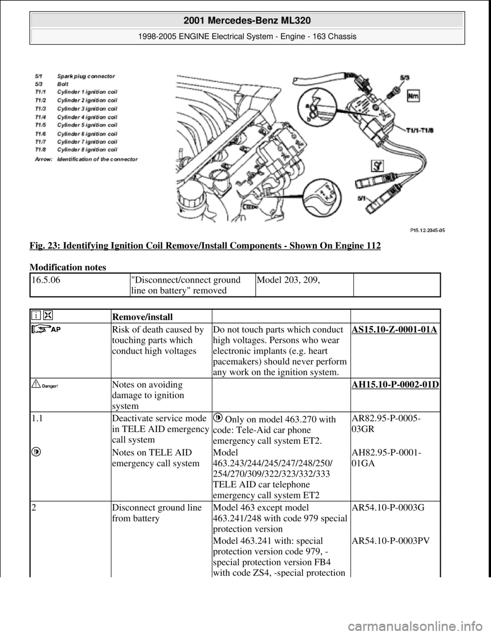
Fig. 23: Identifying Ignition Coil Remove/Install Components - Shown On Engine 112
Modification notes
16.5.06"Disconnect/connect ground
line on battery" removedModel 203, 209,
Remove/install
Risk of death caused by
touching parts which
conduct high voltagesDo not touch parts which conduct
high voltages. Persons who wear
electronic implants (e.g. heart
pacemakers) should never perform
any work on the ignition system.AS15.10-Z-0001-01A
Notes on avoiding
damage to ignition
system AH15.10-P-0002-01D
1.1Deactivate service mode
in TELE AID emergency
call system Only on model 463.270 with
code: Tele-Aid car phone
emergency call system ET2.AR82.95-P-0005-
03GR
Notes on TELE AID
emergency call systemModel
463.243/244/245/247/248/250/
254/270/309/322/323/332/333
TELE AID car telephone
emergency call system ET2AH82.95-P-0001-
01GA
2Disconnect ground line
from batteryModel 463 except model
463.241/248 with code 979 special
protection versionAR54.10-P-0003G
Model 463.241 with: special
protection version code 979, -
special protection version FB4
with code ZS4, -special protection AR54.10-P-0003PV
2001 Mercedes-Benz ML320
1998-2005 ENGINE Electrical System - Engine - 163 Chassis
me
Saturday, October 02, 2010 3:18:54 PMPage 38 © 2006 Mitchell Repair Information Company, LLC.
Page 2193 of 4133
version FB6 with code ZS6, -
special protection version FB7
with code ZS7, additional battery
100 Ah incl. cutoff relay code E26.
Model 463.248 with: special
protection version, code 979, -
special protection version FB6,
code ZS6, -special protection
version FB7, code ZS7, -additional
battery 100 Ah including cutoff
relay, code E26.AR54.10-P-0003PM
3.1Unclip cover on front
side of engineModel 211, 215, 220, 230.475/476
4.1Remove engine cover
with integrated air filterExcept model 170.466,
203.065/076/265/276, 209.376/476
from 24.4.04, 211.076/276,
215.374, 220.074/174, 230.474,
463.270/271
The air filter is integrated in the
engine cover. Remove the engine
cover or the air filter housing by
pulling it from the cylinder head
covers vertically in the upward
direction.
4.2Remove air filter housingModel 170.466, 203.065/265,
211.076/276, 215.374,
220.074/174, 230.474AR09.10-P-1150SVK
Model 203.076 /276, 209.376 /476
from 24.4.04, 171.473AR09.10-P-1150AC
Model 463.270/271AR09.10-P-1150GX
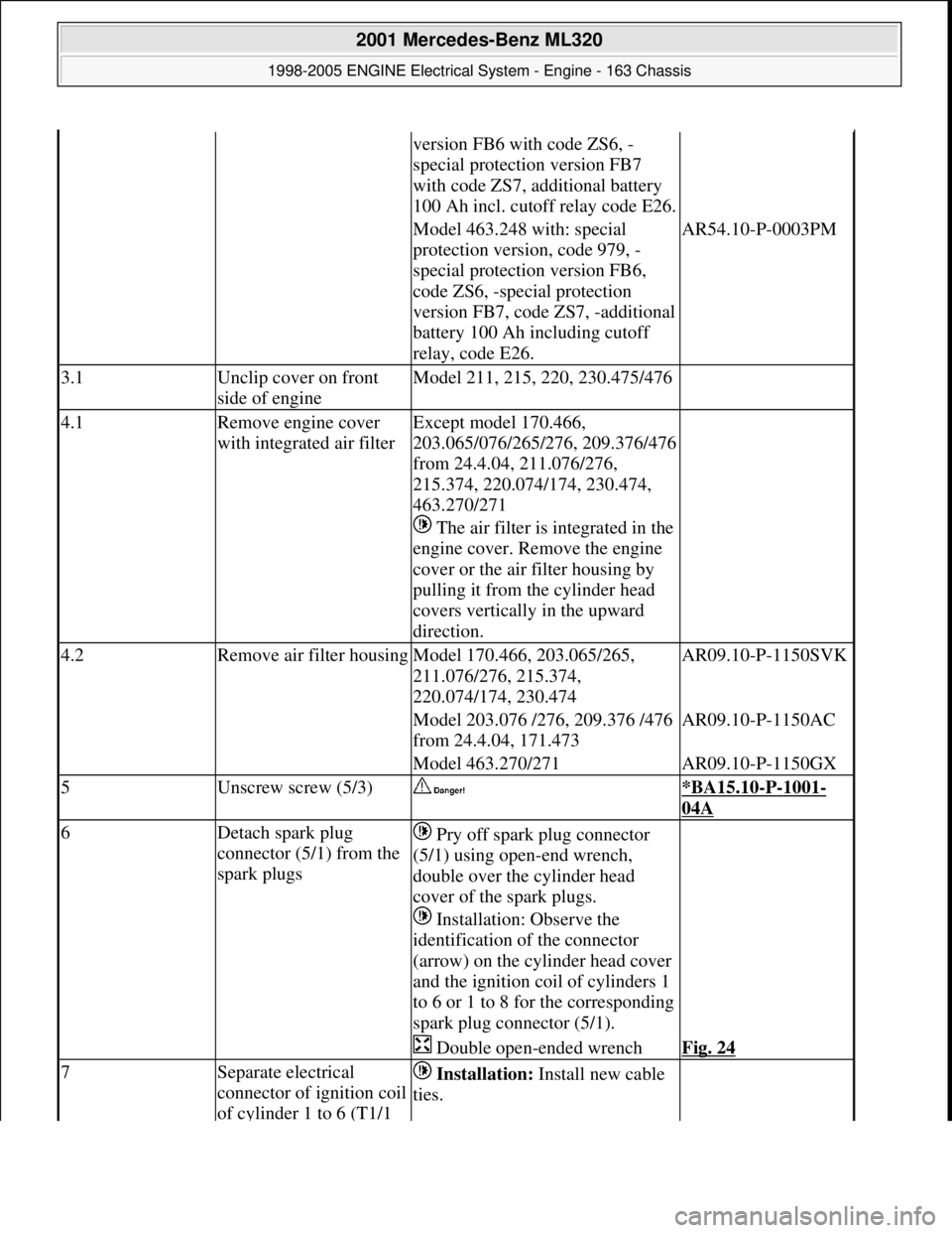
5Unscrew screw (5/3) *BA15.10-P-1001-
04A
6Detach spark plug
connector (5/1) from the
spark plugs Pry off spark plug connector
(5/1) using open-end wrench,
double over the cylinder head
cover of the spark plugs.
Installation: Observe the
identification of the connector
(arrow) on the cylinder head cover
and the ignition coil of cylinders 1
to 6 or 1 to 8 for the corresponding
spark plug connector (5/1).
Double open-ended wrenchFig. 24
7Separate electrical
connector of ignition coil
of cylinder 1 to 6 (T1/1 Installation: Install new cable
ties.
2001 Mercedes-Benz ML320
1998-2005 ENGINE Electrical System - Engine - 163 Chassis
me
Saturday, October 02, 2010 3:18:54 PMPage 39 © 2006 Mitchell Repair Information Company, LLC.
Page 2204 of 4133
ENGINE 112.970 in MODEL 163.157
ENGINE 113.942 in MODEL 163.172
ENGINE 113.981 in MODEL 163.174
ENGINE 113.965 in MODEL 163.175
Fig. 28: Identifying Starter Remove/Install Components
Modification notes
3.9.03Check ring gear, newly
recordedStage 7
Removing/installing
Risk of explosion caused by
oxyhydrogen gas. Risk of
poisoning and caustic burns
caused by swallowing battery
acid. Risk of injury through
burns to skin and eyes from
battery acid or when handling
damaged lead-acid batteriesNo fire, sparks, open
flames or smoking. Wear
acid-resistant gloves,
clothing and safety
glasses. Only pour battery
acid into suitable and
appropriately marked
containers.AS54.10-Z-0001-01A
Notes on self-locking nuts and
bolts AH00.00-N-0001-01A
2001 Mercedes-Benz ML320
1998-2005 ENGINE Electrical System - Engine - 163 Chassis
me
Saturday, October 02, 2010 3:18:54 PMPage 50 © 2006 Mitchell Repair Information Company, LLC.
Page 2205 of 4133
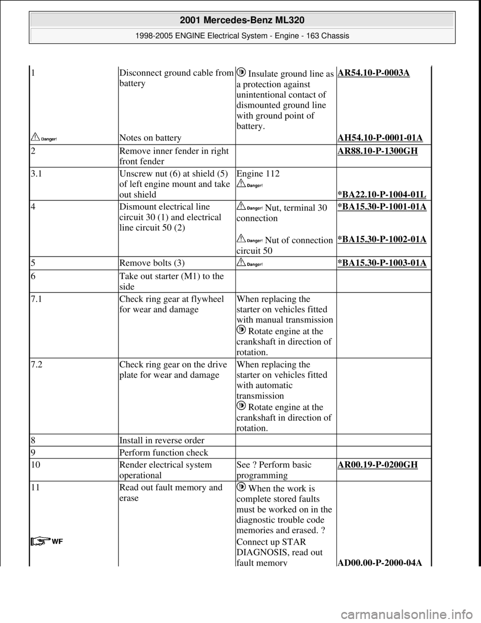
1Disconnect ground cable from
battery Insulate ground line as
a protection against
unintentional contact of
dismounted ground line
with ground point of
battery.AR54.10-P-0003A
Notes on battery AH54.10-P-0001-01A
2Remove inner fender in right
front fender AR88.10-P-1300GH
3.1Unscrew nut (6) at shield (5)
of left engine mount and take
out shieldEngine 112
*BA22.10-P-1004-01L
4Dismount electrical line
circuit 30 (1) and electrical
line circuit 50 (2) Nut, terminal 30
connection*BA15.30-P-1001-01A
Nut of connection
circuit 50*BA15.30-P-1002-01A
5Remove bolts (3) *BA15.30-P-1003-01A
6Take out starter (M1) to the
side
7.1Check ring gear at flywheel
for wear and damageWhen replacing the
starter on vehicles fitted
with manual transmission
Rotate engine at the
crankshaft in direction of
rotation.
7.2Check ring gear on the drive
plate for wear and damageWhen replacing the
starter on vehicles fitted
with automatic
transmission
Rotate engine at the
crankshaft in direction of
rotation.
8Install in reverse order
9Perform function check
10Render electrical system
operationalSee ? Perform basic
programmingAR00.19-P-0200GH
11Read out fault memory and
erase When the work is
complete stored faults
must be worked on in the
diagnostic trouble code
memories and erased. ?
Connect up STAR
DIAGNOSIS, read out
fault memory
AD00.00-P-2000-04A
2001 Mercedes-Benz ML320
1998-2005 ENGINE Electrical System - Engine - 163 Chassis
me
Saturday, October 02, 2010 3:18:54 PMPage 51 © 2006 Mitchell Repair Information Company, LLC.
Page 2206 of 4133
Starter
Engine mounts, engine supports
PREREQUISITES FOR TESTING GENERATOR - AR15.40-P-5009GH
ENGINE 111.977, 112.942/970, 113.942/965/981, 612.963, 628.963 in MODEL 163
Fig. 29: Connection Schematic Between Battery And Alternator
NumberDesignationEngine 112 except
112.951, 113.94/ 96/98
BA15.30-P-1001-01ANut for connection of
circuit 30Nm14
BA15.30-P-1002-01ANut for connection of
circuit 50Nm6
BA15.30-P-1003-01ABolt for starter on
crankcaseNm42
NumberDesignationEngines 112.942/970
113.942/965/981 in model
163.154/157/17 2/174/175
BA22.10-P-1004-01LBolt for front engine
mount on engine supportNm65
Remove/Install
1Open engine hood and raise Up to A145272, X708318.AR88.40-P-1000GH
2001 Mercedes-Benz ML320
1998-2005 ENGINE Electrical System - Engine - 163 Chassis
me
Saturday, October 02, 2010 3:18:54 PMPage 52 © 2006 Mitchell Repair Information Company, LLC.
Page 2207 of 4133
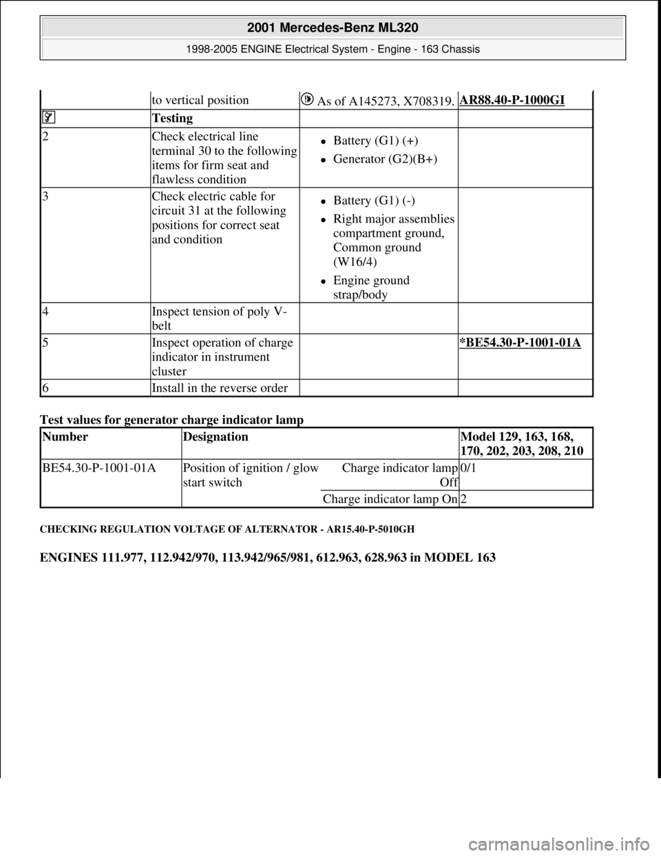
Test values for generator charge indicator lamp
CHECKING REGULATION VOLTAGE OF ALTERNATOR - AR15.40-P-5010GH
ENGINES 111.977, 112.942/970, 113.942/965/981, 612.963, 628.963 in MODEL 163
to vertical position As of A145273, X708319.AR88.40-P-1000GI
Testing
2Check electrical line
terminal 30 to the following
items for firm seat and
flawless conditionBattery (G1) (+)
Generator (G2)(B+)
3Check electric cable for
circuit 31 at the following
positions for correct seat
and conditionBattery (G1) (-)
Right major assemblies
compartment ground,
Common ground
(W16/4)
Engine ground
strap/body
4Inspect tension of poly V-
belt
5Inspect operation of charge
indicator in instrument
cluster *BE54.30-P-1001-01A
6Install in the reverse order
NumberDesignationModel 129, 163, 168,
170, 202, 203, 208, 210
BE54.30-P-1001-01APosition of ignition / glow
start switchCharge indicator lamp
Of
f
0/1
Charge indicator lamp On2
2001 Mercedes-Benz ML320
1998-2005 ENGINE Electrical System - Engine - 163 Chassis
me
Saturday, October 02, 2010 3:18:54 PMPage 53 © 2006 Mitchell Repair Information Company, LLC.
Page 2208 of 4133
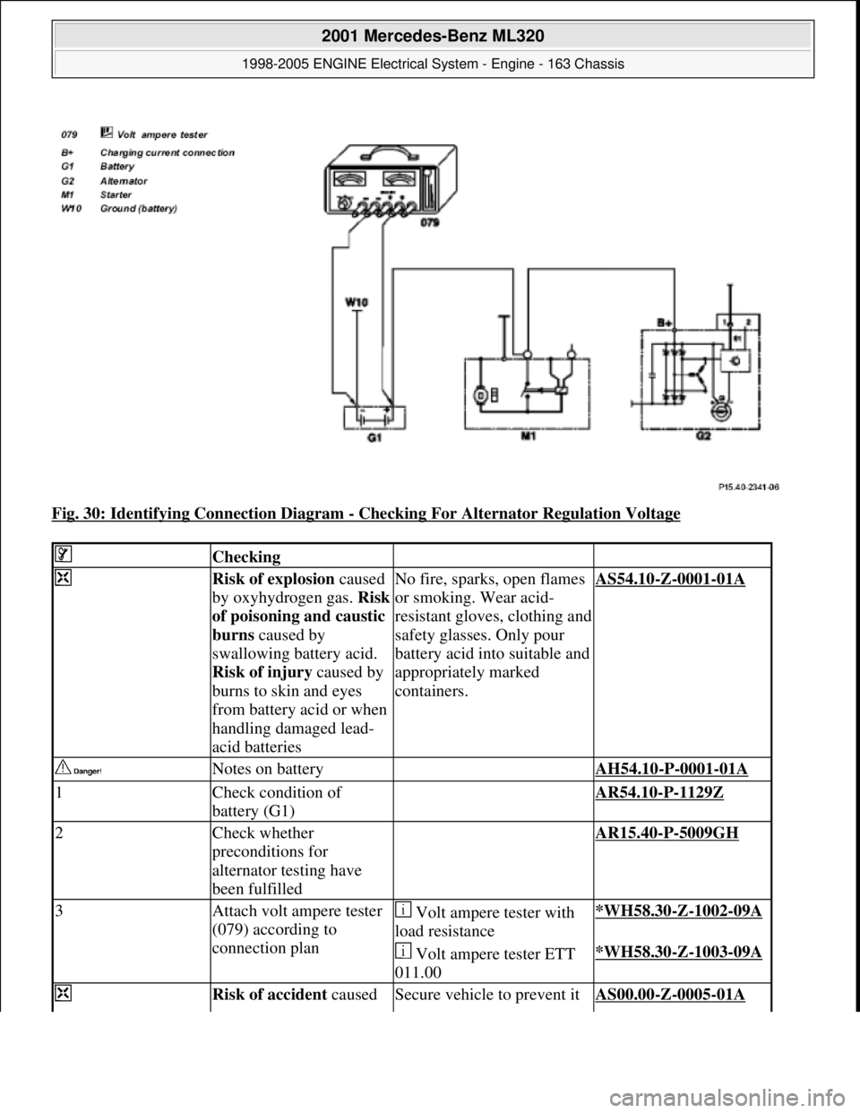
Fig. 30: Identifying Connection Diagram - Checking For Alternator Regulation Voltage
Checking
Risk of explosion caused
by oxyhydrogen gas. Risk
of poisoning and caustic
burns caused by
swallowing battery acid.
Risk of injury caused by
burns to skin and eyes
from battery acid or when
handling damaged lead-
acid batteriesNo fire, sparks, open flames
or smoking. Wear acid-
resistant gloves, clothing and
safety glasses. Only pour
battery acid into suitable and
appropriately marked
containers.
AS54.10-Z-0001-01A
Notes on battery AH54.10-P-0001-01A
1Check condition of
battery (G1) AR54.10-P-1129Z
2Check whether
preconditions for
alternator testing have
been fulfilled AR15.40-P-5009GH
3Attach volt ampere tester
(079) according to
connection plan Volt ampere tester with
load resistance*WH58.30-Z-1002-09A
Volt ampere tester ETT
011.00*WH58.30-Z-1003-09A
Risk of accident caused Secure vehicle to prevent it AS00.00-Z-0005-01A
2001 Mercedes-Benz ML320
1998-2005 ENGINE Electrical System - Engine - 163 Chassis
me
Saturday, October 02, 2010 3:18:54 PMPage 54 © 2006 Mitchell Repair Information Company, LLC.