1997 MERCEDES-BENZ ML430 battery
[x] Cancel search: batteryPage 2052 of 4133

Connect DC clip-on probe from engine tester with oscilloscope to positive battery terminal. See Fig. 11. Start
engine. Switch on low beam. Access diode test at 3000 RPM. See Fig. 12
-Fig. 14 . Replace generator as
necessar
y.
2001 Mercedes-Benz ML320
2001-04 STARTING & CHARGING SYSTEMS Generators & Regulators - 163 Chassis
me
Saturday, October 02, 2010 3:20:32 PMPage 18 © 2006 Mitchell Repair Information Company, LLC.
Page 2056 of 4133
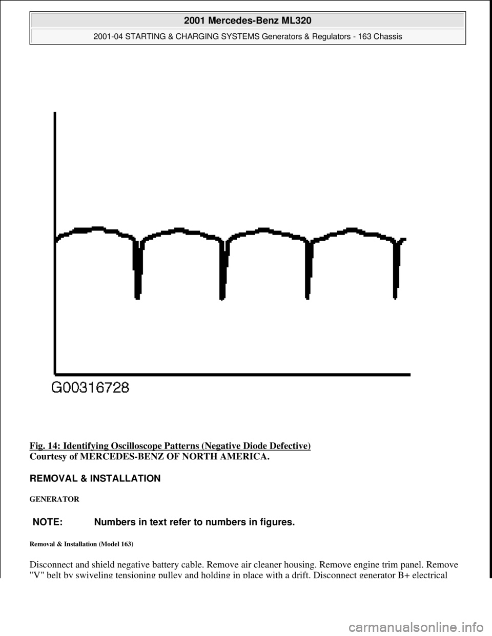
Fig. 14: Identifying Oscilloscope Patterns (Negative Diode Defective)
Courtesy of MERCEDES-BENZ OF NORTH AMERICA.
REMOVAL & INSTALLATION
GENERATOR
Removal & Installation (Model 163)
Disconnect and shield negative battery cable. Remove air cleaner housing. Remove engine trim panel. Remove
"V" belt b
y swiveling tensioning pulley and holding in place with a drift. Disconnect generator B+ electrical
NOTE: Numbers in text refer to numbers in figures.
2001 Mercedes-Benz ML320
2001-04 STARTING & CHARGING SYSTEMS Generators & Regulators - 163 Chassis
me
Saturday, October 02, 2010 3:20:32 PMPage 22 © 2006 Mitchell Repair Information Company, LLC.
Page 2057 of 4133
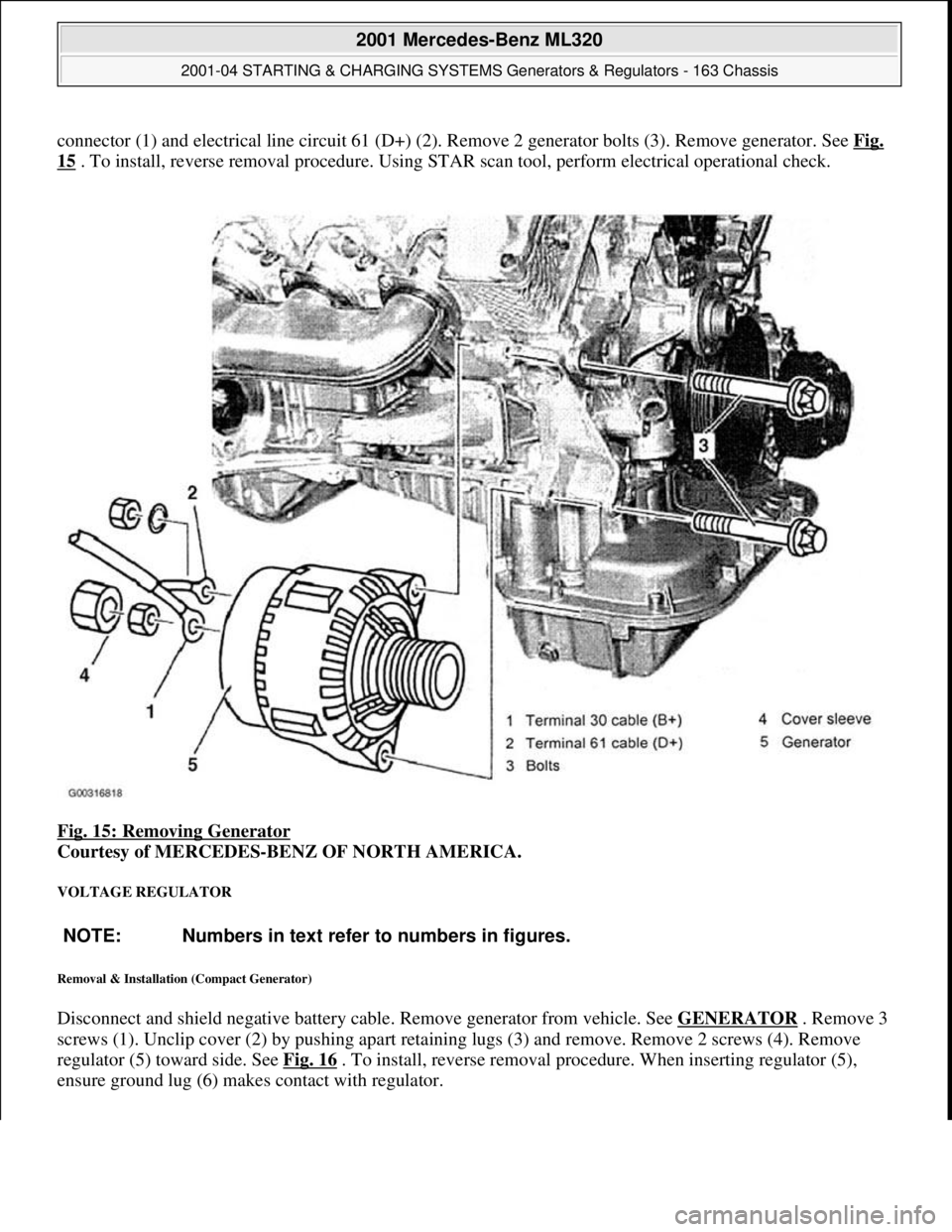
connector (1) and electrical line circuit 61 (D+) (2). Remove 2 generator bolts (3). Remove generator. See Fig.
15 . To install, reverse removal procedure. Using STAR scan tool, perform electrical operational check.
Fig. 15: Removing Generator
Courtesy of MERCEDES-BENZ OF NORTH AMERICA.
VOLTAGE REGULATOR
Removal & Installation (Compact Generator)
Disconnect and shield negative battery cable. Remove generator from vehicle. See GENERATOR . Remove 3
screws (1). Unclip cover (2) by pushing apart retaining lugs (3) and remove. Remove 2 screws (4). Remove
regulator (5) toward side. See Fig. 16
. To install, reverse removal procedure. When inserting regulator (5),
ensure
ground lug (6) makes contact with regulator.
NOTE: Numbers in text refer to numbers in figures.
2001 Mercedes-Benz ML320
2001-04 STARTING & CHARGING SYSTEMS Generators & Regulators - 163 Chassis
me
Saturday, October 02, 2010 3:20:32 PMPage 23 © 2006 Mitchell Repair Information Company, LLC.
Page 2058 of 4133
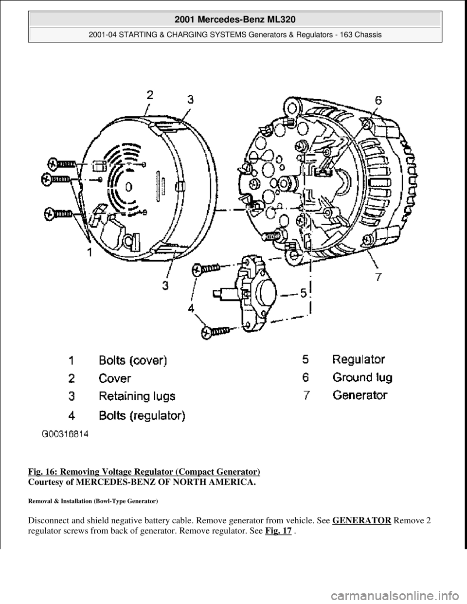
Fig. 16: Removing Voltage Re gulator (Compact Generator)
Courtesy of MERCEDES-BENZ OF NORTH AMERICA.
Removal & Installation (Bowl-Type Generator)
Disconnect and shield negative battery cable. Remove generator from vehicle. See GENERATOR Remove 2
re
gulator screws from back of generator. Remove regulator. See Fig. 17.
2001 Mercedes-Benz ML320
2001-04 STARTING & CHARGING SYSTEMS Gene rators & Regulators - 163 Chassis
me
Saturday, October 02, 2010 3:20:32 PMPage 24 © 2006 Mitchell Repair Information Company, LLC.
Page 2086 of 4133
P01.30-0299-06
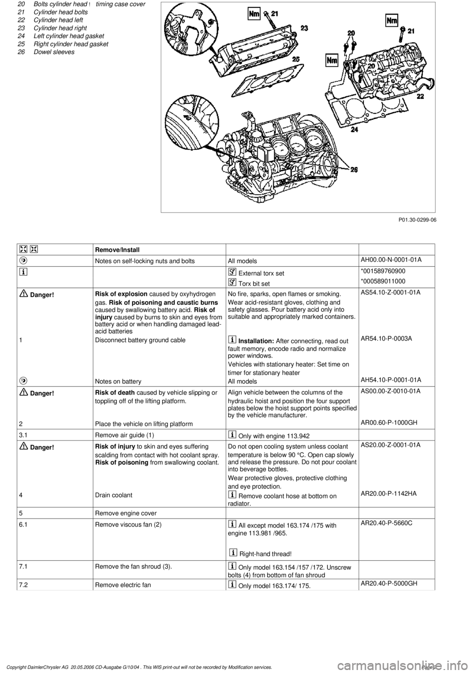
20
Bolts cylinder head
!
timing case cover
21
Cylinder head bolts
22
Cylinder head left
23
Cylinder head right
24
Left cylinder head gasket
25
Right cylinder head gasket
26
Dowel sleeves
Remove/Install
Notes on self-locking nuts and bolts
All models
AH00.00-N-0001-01A
External torx set
*001589760900
Torx bit set
*000589011000
Danger!
Risk of explosion
caused by oxyhydrogen
gas.
Risk of poisoning and caustic burns
caused by swallowing battery acid.
Risk of
injury caused by burns to skin and eyes from
battery acid or when handling damaged lead-
acid batteries
No fire, sparks, open flames or smoking.
Wear acid-resistant gloves, clothing and
safety glasses. Pour battery acid only into
suitable and appropriately marked containers.
AS54.10-Z-0001-01A
1
Disconnect battery ground cable
Installation:
After connecting, read out
fault memory, encode radio and normalize
power windows.
Vehicles with stationary heater: Set time on
timer for stationary heater
AR54.10-P-0003A
Notes on battery
All models
AH54.10-P-0001-01A
Danger!
Risk of death
caused by vehicle slipping or
toppling off of the lifting platform.
Align vehicle between the columns of the
hydraulic hoist and position the four support
plates below the hoist support points specified
by the vehicle manufacturer.
AS00.00-Z-0010-01A
2
Place the vehicle on lifting platform
AR00.60-P-1000GH
3.1
Remove air guide (1)
Only with engine 113.942
Danger!
Risk of injury
to skin and eyes suffering
scalding from contact with hot coolant spray.
Risk of poisoning
from swallowing coolant.
Do not open cooling system unless coolant
temperature is below 90 °C. Open cap slowly
and release the pressure. Do not pour coolant
into beverage bottles.
Wear protective gloves, protective clothing
and eye protection.
AS20.00-Z-0001-01A
4
Drain coolant
Remove coolant hose at bottom on
radiator.
AR20.00-P-1142HA
5
Remove engine cover
6.1
Remove viscous fan (2)
All except model 163.174 /175 with
engine 113.981 /965.
Right-hand thread!
AR20.40-P-5660C
7.1
Remove the fan shroud (3).
Only model 163.154 /157 /172. Unscrew
bolts (4) from bottom of fan shroud
7.2
Remove electric fan
Only model 163.174/ 175.
AR20.40-P-5000GH
Copyright DaimlerChrysler AG 20.05.2006 CD-Ausgabe G/10/04 . This WIS print-out will not be recorde
d by Modification services.
Page 2
Page 2094 of 4133
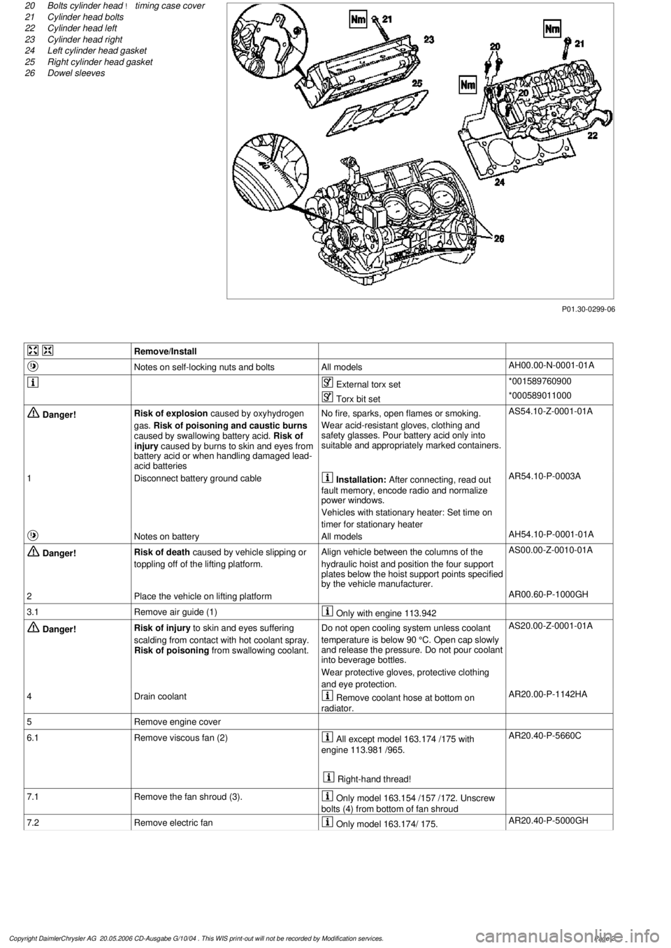
P01.30-0299-06
20
Bolts cylinder head
!
timing case cover
21
Cylinder head bolts
22
Cylinder head left
23
Cylinder head right
24
Left cylinder head gasket
25
Right cylinder head gasket
26
Dowel sleeves
Remove/Install
Notes on self-locking nuts and bolts
All models
AH00.00-N-0001-01A
External torx set
*001589760900
Torx bit set
*000589011000
Danger!
Risk of explosion
caused by oxyhydrogen
gas.
Risk of poisoning and caustic burns
caused by swallowing battery acid.
Risk of
injury caused by burns to skin and eyes from
battery acid or when handling damaged lead-
acid batteries
No fire, sparks, open flames or smoking.
Wear acid-resistant gloves, clothing and
safety glasses. Pour battery acid only into
suitable and appropriately marked containers.
AS54.10-Z-0001-01A
1
Disconnect battery ground cable
Installation:
After connecting, read out
fault memory, encode radio and normalize
power windows.
Vehicles with stationary heater: Set time on
timer for stationary heater
AR54.10-P-0003A
Notes on battery
All models
AH54.10-P-0001-01A
Danger!
Risk of death
caused by vehicle slipping or
toppling off of the lifting platform.
Align vehicle between the columns of the
hydraulic hoist and position the four support
plates below the hoist support points specified
by the vehicle manufacturer.
AS00.00-Z-0010-01A
2
Place the vehicle on lifting platform
AR00.60-P-1000GH
3.1
Remove air guide (1)
Only with engine 113.942
Danger!
Risk of injury
to skin and eyes suffering
scalding from contact with hot coolant spray.
Risk of poisoning
from swallowing coolant.
Do not open cooling system unless coolant
temperature is below 90 °C. Open cap slowly
and release the pressure. Do not pour coolant
into beverage bottles.
Wear protective gloves, protective clothing
and eye protection.
AS20.00-Z-0001-01A
4
Drain coolant
Remove coolant hose at bottom on
radiator.
AR20.00-P-1142HA
5
Remove engine cover
6.1
Remove viscous fan (2)
All except model 163.174 /175 with
engine 113.981 /965.
Right-hand thread!
AR20.40-P-5660C
7.1
Remove the fan shroud (3).
Only model 163.154 /157 /172. Unscrew
bolts (4) from bottom of fan shroud
7.2
Remove electric fan
Only model 163.174/ 175.
AR20.40-P-5000GH
Copyright DaimlerChrysler AG 20.05.2006 CD-Ausgabe G/10/04 . This WIS print-out will not be recorde
d by Modification services.
Page 2
Page 2134 of 4133

1.1
Unscrew bolts at rear of 2/3 seat bench and
raise rear of seat bench
Up to VIN A145272, X708318.
1.2
Remove covers at seat frame of 60% bench
seat
As of VIN A145273, X708319.
AR91.12-P-1100GH
Only remove the covers which are
identified in the document with A, D and E.
2.1
Fold 60% bench seat forward into footwell
As of VIN A145273, X708319. See
operator's manual.
3.1
Pull floor covering below rear seat mounting
bracket (1) of 60% seat forward
Carefully pull floor covering forward under
the seat console to prevent it from tearing.
As of VIN A145273, X708319.
4.1
Pull the floor covering forward under the front
corner of the left C-pillar cover (2)
Carefully pull the floor covering forward
under the cover to prevent it from tearing.
As of VIN A145273, X708319.
5
Cut into floor covering directly behind seat
retaining cable (3)
Ensure that the wiring harness (4) is not
damaged when cutting the floor covering.
As of VIN A145273, X708319. Broken
line marks the cut.
6
Fold floor mat back
Do not crease floor mat!
Fold floor mat back far enough to provide
access to cap (84) between body and fuel
pump.
7
Remove end cover (84) of body
Installation:
Replace cap and insert with
new sealing compound.
Cap (84) is sealed in with body sealer.
Heat with hot air blower to make it easier to
remove.
8
Seal fuel return line (90/11)
Pliers
*163589003700
9
Connect extraction hose (90/14) with adapter
hose to connection for fuel return line (90/11)
Extraction hose
*168589009000
Adapter hose
*163589009100
10
Connect ground cable (90/10) of extraction
pump ground terminal vehicle battery
Pumping out
11
Pump fuel out into safety container using
extraction pump
*BF47.10-P-1001-01A
*WH58.30-Z-1001-16A
12
Install in the reverse order
Fuel tank
Number
Designation
Models
163.113/
136/154/
172 up to
31.08.01
Models
163.113/
136/154/
172 as of
01.09.01
Models
163.157/
175
Model
163.128
Model
163.174
BF47.10-P-1001-01A
Fuel tank capacity
Total capacity
Liter
72838393
Reserve capacity
Liter
10121212
Copyright DaimlerChrysler AG 28.05.2006 CD-Ausgabe G/10/04 . This WIS print-out will not be recorde
d by Modification services.
Page 2
Page 2139 of 4133

GF54.21-P-4106-01GH
Extended Activity Module - Task
n
The primary tasks of the Extended Activity Module (EAM, N10/1) are
as follows:
D
To control the door sill lights
D
To suppress the auto-dimming mirror function
D
To control the headlight cleaning system (HCS)
D
To control the rear window defroster
D
To control seat heating
D
To control the power supply via control console to tilt/sliding or
louvered sunroof switch
D
To control the PTC heater booster (R22/3)
D
To control the auxiliary fan (M4)
D
To read the cruise control switch (S40) and relay data to control
module (DAS, N73/1)
D
To read the contacts for wiper speed settings 1 and 2 on
combination switch (S4) for diagnosis.
To perform these tasks the Extended Activity Module (EAM, N10/1)
reads various signals and switch settings directly.
The Extended Activity Module (EAM, N10/1) interfaces with other
control modules via the engine compartment CAN.
-----------------------------------------------------------------------------------------
Diagnosis
Diagnosis is performed using the Star diagnostic tool. To facilitate
this task, the Extended Activity Module (EAM, N10/1) is equipped
with its own diagnostics cable.
This cable is also used to diagnose the
All Activity Module (AAM,
N10)
and the
transfer case control module (N78)
.
The Extended Activity Module (EAM, N10/1) is linked to the All
Activity Module (AAM, N10) via the
engine compartment CAN
.
Data communication between the All Activity Module (AAM,
N10) and the Extended Activity Module (EAM, N10/1) is
assumed by the
CAN (N10 - N10/1)
when terminal 15 is off.
The CAN (N10 - N10/1)
is an independent CAN bus located
between the All Activity Module (AAM, N10) and the Extended
Activity Module (EAM, N10/1).
No other
control modules are
connected to the CAN (N10 - N10/1).
-----------------------------------------------------------------------------------------
Details:
Door sill lights
When the front interior light is on and one of the front doors is open,
or when the rear interior light is on and one of the back doors is open,
the door sill lights for the open door will illuminate.
Headlight cleaning system (HCS)
Activating a separate switch causes the EAM to send a turn-on signal
to the HCS pump relay.
EAM will send an additional turn-on signal to the HCS pump relay
only after the cleaning operation is completed and a "rest period" of
approximately 2.5 sec. has passed.
Auto-dimming mirror function
The auto-dimming mirror function is suppressed when the interior
light is on or reverse gear is engaged.
Auto-dimming suppression for the outside rearview mirror (slave) is
activated by the inside rearview mirror (master).
Heater booster/PTC air heater for diesel engines
EAM monitors system voltage and adjusts heater booster capacity to
minimize load on battery.
Rear window defroster
EAM sets maximum ON time for rear window defroster depending
on outdoor temperature and current vehicle speed.
D
Standard ON time:
10 min.
D
Outdoor temperature < 5
o
C:
Additional 5 min.
D
Speed >80 km/h:
Additional 3 min.
Seat heating
Sets maximum seat heating time.
D
Setting 1: max. 20 min.
D
Setting 2: max. 5 min.
Tilt/sliding or louvered sunroofs
Signal via AAM2 allows operation of tilt/sliding or louvered sunroofs
when ignition is on (standard mode) or off (keyless mode).
Ignition authorization via CAN
The EAM issues ignition authorization to AAM2 via the engine
compartment CAN depending on the requirements of the engine
control unit in connection with the FBM.
Copyright DaimlerChrysler AG 18.05.2006 CD-Ausgabe G/10/04 . This WIS print-out will not be recorde
d by Modification services.
Page 1