Page 1717 of 4133
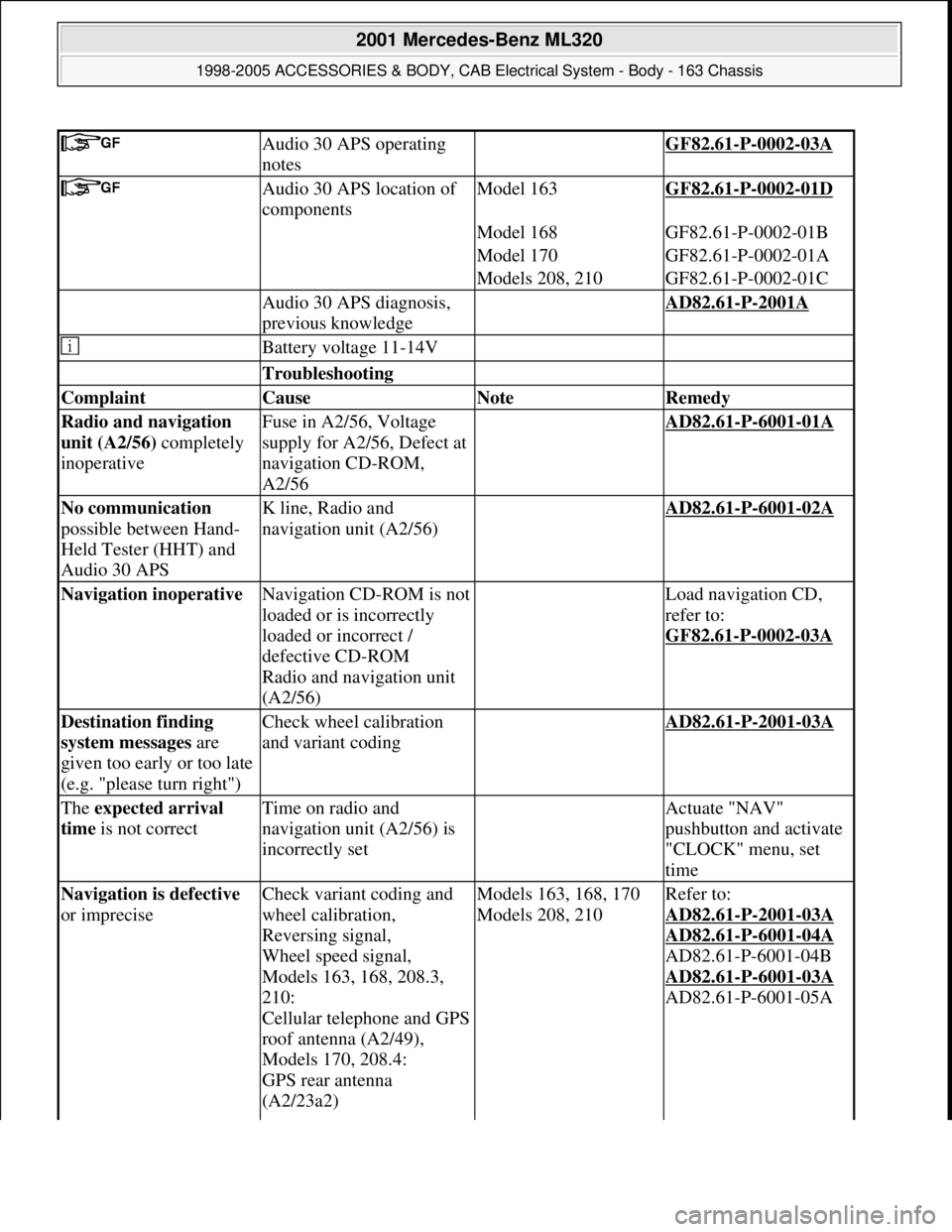
Audio 30 APS operating
notes GF82.61-P-0002-03A
Audio 30 APS location of
componentsModel 163GF82.61-P-0002-01D
Model 168GF82.61-P-0002-01B
Model 170GF82.61-P-0002-01A
Models 208, 210GF82.61-P-0002-01C
Audio 30 APS diagnosis,
previous knowledge AD82.61-P-2001A
Battery voltage 11-14V
Troubleshooting
Complaint Cause Note Remedy
Radio and navigation
unit (A2/56) completely
inoperativeFuse in A2/56, Voltage
supply for A2/56, Defect at
navigation CD-ROM,
A2/56 AD82.61-P-6001-01A
No communication
possible between Hand-
Held Tester (HHT) and
Audio 30 APSK line, Radio and
navigation unit (A2/56) AD82.61-P-6001-02A
Navigation inoperative Navigation CD-ROM is not
loaded or is incorrectly
loaded or incorrect /
defective CD-ROM
Radio and navigation unit
(A2/56) Load navigation CD,
refer to:
GF82.61
-P-0002-03A
Destination finding
system messages are
given too early or too late
(e.g. "please turn right")Check wheel calibration
and variant coding AD82.61-P-2001-03A
The expected arrival
time is not correctTime on radio and
navigation unit (A2/56) is
incorrectly set Actuate "NAV"
pushbutton and activate
"CLOCK" menu, set
time
Navigation is defective
or impreciseCheck variant coding and
wheel calibration,
Reversing signal,
Wheel speed signal,
Models 163, 168, 208.3,
210:
Cellular telephone and GPS
roof antenna (A2/49),
Models 170, 208.4:
GPS rear antenna
(A2/23a2) Models 163, 168, 170
Models 208, 210Refer to:
AD82.61
-P-2001-03A
AD82.61
-P-6001-04A
AD82.61-P-6001-04B
AD82.61
-P-6001-03A
AD82.61-P-6001-05A
2001 Mercedes-Benz ML320
1998-2005 ACCESSORIES & BODY, CAB Electrical System - Body - 163 Chassis
me
Saturday, October 02, 2010 3:30:08 PMPage 222 © 2006 Mitchell Repair Information Company, LLC.
Page 1722 of 4133
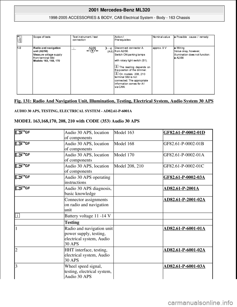
Fig. 131: Radio And Navigation Unit, Illumination, Testing, Electrical System, Audio System 30 APS
AUDIO 30 APS, TESTING, ELECTRICAL SYSTEM - AD82.61-P-6001A
MODEL 163,168,170, 208, 210 with CODE (353) Audio 30 APS
Audio 30 APS, location
of componentsModel 163GF82.61-P-0002-01D
Audio 30 APS, location
of componentsModel 168GF82.61-P-0002-01B
Audio 30 APS, location
of componentsModel 170GF82.61-P-0002-01A
Audio 30 APS, location
of componentsModel 208, 210GF82.61-P-0002-01C
Audio 30 APS operating
instructions GF82.61-P-0002-03A
Audio 30 APS diagnosis,
basic knowledge AD82.61-P-2001A
Connector assignments
on radio and navigation
unit AD82.61-P-2001-02A
Battery voltage 11 -14 V
Testing
1Radio and navigation unit
power supply, testing,
electrical system, Audio
30 APS AD82.61-P-6001-01A
2HHT interface, testing,
electrical system, Audio
30 APS AD82.61-P-6001-02A
3Wheel speed signal,
testing, electrical system,
Audio 30 APS AD82.61-P-6001-03A
2001 Mercedes-Benz ML320
1998-2005 ACCESSORIES & BODY, CAB Electrical System - Body - 163 Chassis
me
Saturday, October 02, 2010 3:30:08 PMPage 227 © 2006 Mitchell Repair Information Company, LLC.
Page 1732 of 4133
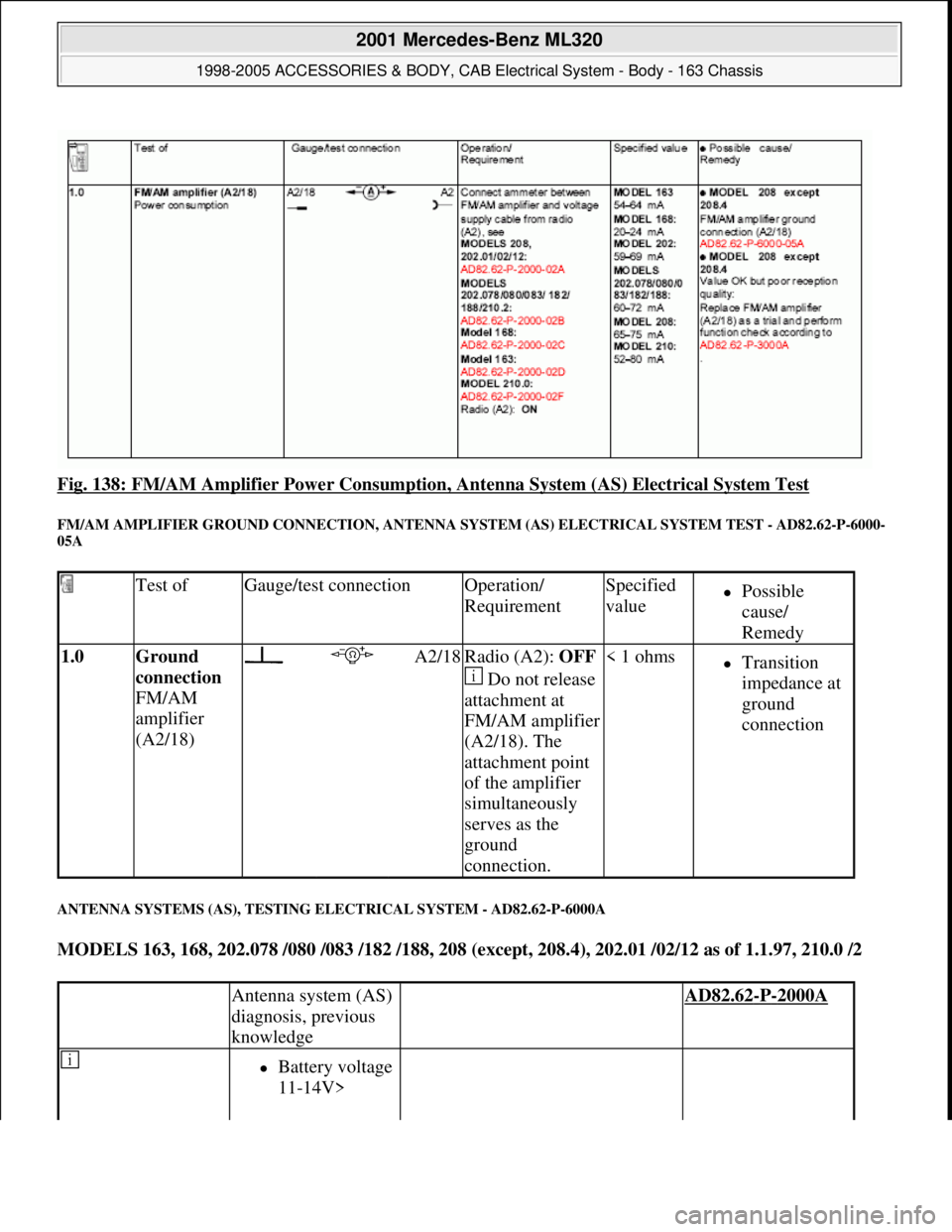
Fig. 138: FM/AM Amplifier Power Consumption, Antenna System (AS) Electrical System Test
FM/AM AMPLIFIER GROUND CONNECTION, ANTENNA SYSTEM (AS) ELECTRICAL SYSTEM TEST - AD82.62-P-6000-
05A
ANTENNA SYSTEMS (AS), TESTING ELECTRICAL SYSTEM - AD82.62-P-6000A
MODELS 163, 168, 202.078 /080 /083 /182 /188, 208 (except, 208.4), 202.01 /02/12 as of 1.1.97, 210.0 /2
Test ofGauge/test connectionOperation/
RequirementSpecified
valuePossible
cause/
Remedy
1.0 Ground
connection
FM/AM
amplifier
(A2/18) A2/18Radio (A2): OFF
Do not release
attachment at
FM/AM amplifier
(A2/18). The
attachment point
of the amplifier
simultaneously
serves as the
ground
connection.< 1 ohmsTransition
impedance at
ground
connection
Antenna system (AS)
diagnosis, previous
knowledge AD82.62-P-2000A
Battery voltage
11-14V>
2001 Mercedes-Benz ML320
1998-2005 ACCESSORIES & BODY, CAB Electrical System - Body - 163 Chassis
me
Saturday, October 02, 2010 3:30:08 PMPage 237 © 2006 Mitchell Repair Information Company, LLC.
Page 1738 of 4133
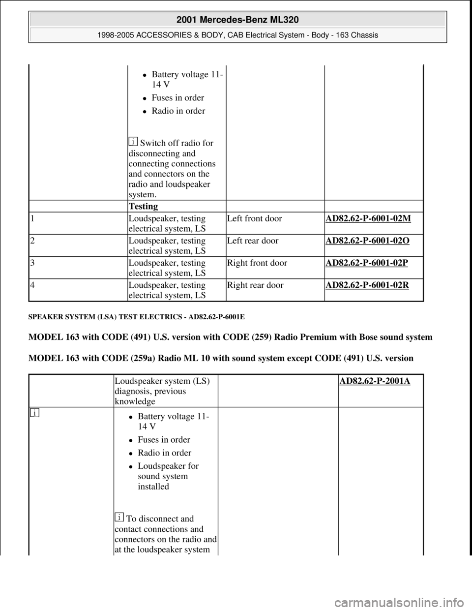
SPEAKER SYSTEM (LSA) TEST ELECTRICS - AD82.62-P-6001E
MODEL 163 with CODE (491) U.S. version with CODE (259) Radio Premium with Bose sound system
MODEL 163 with CODE (259a) Radio ML 10 with sound system except CODE (491) U.S. version
Battery voltage 11-
14 V
Fuses in order
Radio in order
Switch off radio for
disconnecting and
connecting connections
and connectors on the
radio and loudspeaker
system.
Testing
1Loudspeaker, testing
electrical system, LSLeft front doorAD82.62-P-6001-02M
2Loudspeaker, testing
electrical system, LSLeft rear doorAD82.62-P-6001-02O
3Loudspeaker, testing
electrical system, LSRight front doorAD82.62-P-6001-02P
4Loudspeaker, testing
electrical system, LSRight rear doorAD82.62-P-6001-02R
Loudspeaker system (LS)
diagnosis, previous
knowledge AD82.62-P-2001A
Battery voltage 11-
14 V
Fuses in order
Radio in order
Loudspeaker for
sound system
installed
To disconnect and
contact connections and
connectors on the radio and
at the loudspeaker system
2001 Mercedes-Benz ML320
1998-2005 ACCESSORIES & BODY, CAB Electrical System - Body - 163 Chassis
me
Saturday, October 02, 2010 3:30:08 PMPage 243 © 2006 Mitchell Repair Information Company, LLC.
Page 1741 of 4133
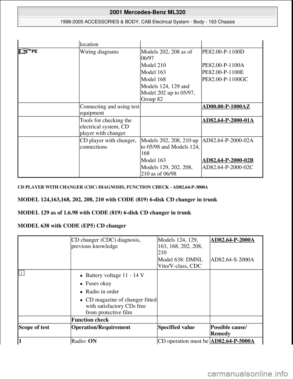
CD PLAYER WITH CHANGER (CDC) DIAGNOSIS, FUNCTION CHECK - AD82.64-P-3000A
MODEL 124,163,168, 202, 208, 210 with CODE (819) 6-disk CD changer in trunk
MODEL 129 as of 1.6.98 with CODE (819) 6-disk CD changer in trunk
MODEL 638 with CODE (EP5) CD changer
location
Wiring diagramsModels 202, 208 as of
06/97PE82.00-P-1100D
Model 210PE82.00-P-1100A
Model 163PE82.00-P-1100E
Model 168PE82.00-P-1100GC
Models 124, 129 and
Model 202 up to 05/97,
Group 82
Connecting and using test
equipment AD00.00-P-1000AZ
Tools for checking the
electrical system, CD
player with changer AD82.64-P-2000-01A
CD player with changer,
connectionsModels 202, 208, 210 up
to 05/98 and Models 124,
168AD82.64-P-2000-02A
Model 163AD82.64-P-2000-02B
Models 129, 202, 208,
210 as of 06/98AD82.64-P-2000-02C
CD changer (CDC) diagnosis,
previous knowledgeModels 124, 129,
163, 168, 202, 208,
210AD82.64-P-2000A
Model 638: DMNL
Vito/V-class, CDCAD82.64-S-2000A
Battery voltage 11 - 14 V
Fuses okay
Radio in order
CD magazine of changer fitted
with satisfactory CDs free
from protective film
Function check
Scope of test Operation/Requirement Specified value Possible cause/
Remedy
1 Radio: ON CD operation must be AD82.64-P-5000A
2001 Mercedes-Benz ML320
1998-2005 ACCESSORIES & BODY, CAB Electrical System - Body - 163 Chassis
me
Saturday, October 02, 2010 3:30:08 PMPage 246 © 2006 Mitchell Repair Information Company, LLC.
Page 1744 of 4133
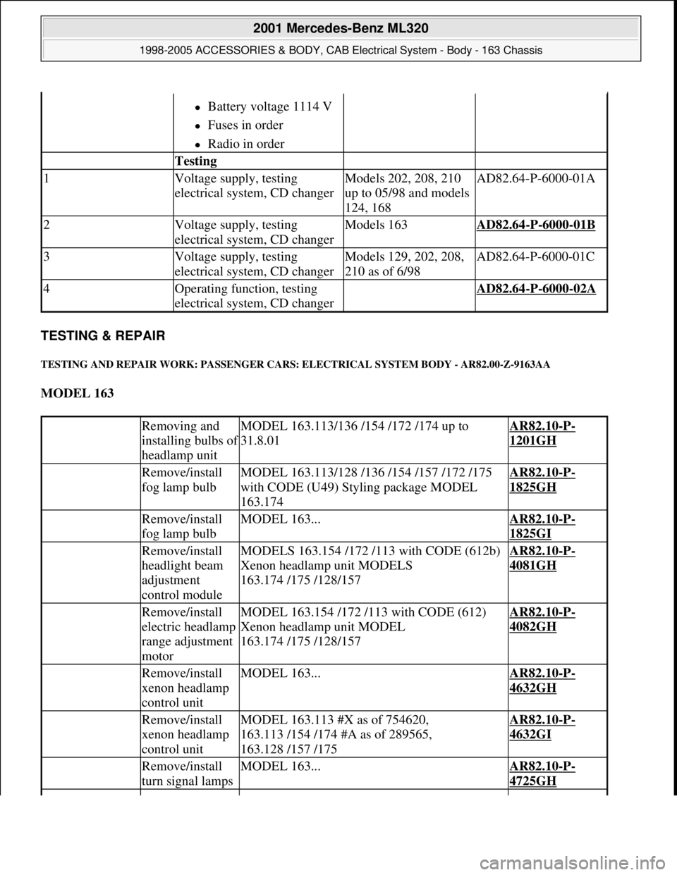
TESTING & REPAIR
TESTING AND REPAIR WORK: PASSENGER CARS: ELECTRICAL SYSTEM BODY - AR82.00-Z-9163AA
MODEL 163
Battery voltage 1114 V
Fuses in order
Radio in order
Testing
1Voltage supply, testing
electrical system, CD changerModels 202, 208, 210
up to 05/98 and models
124, 168AD82.64-P-6000-01A
2Voltage supply, testing
electrical system, CD changerModels 163AD82.64-P-6000-01B
3Voltage supply, testing
electrical system, CD changerModels 129, 202, 208,
210 as of 6/98AD82.64-P-6000-01C
4Operating function, testing
electrical system, CD changer AD82.64-P-6000-02A
Removing and
installing bulbs o
f
headlamp unit
MODEL 163.113/136 /154 /172 /174 up to
31.8.01AR82.10-P-
1201GH
Remove/install
fog lamp bulbMODEL 163.113/128 /136 /154 /157 /172 /175
with CODE (U49) Styling package MODEL
163.174AR82.10-P-
1825GH
Remove/install
fog lamp bulbMODEL 163...AR82.10-P-
1825GI
Remove/install
headlight beam
adjustment
control moduleMODELS 163.154 /172 /113 with CODE (612b)
Xenon headlamp unit MODELS
163.174 /175 /128/157AR82.10-P-
4081GH
Remove/install
electric headlamp
range adjustment
motorMODEL 163.154 /172 /113 with CODE (612)
Xenon headlamp unit MODEL
163.174 /175 /128/157AR82.10-P-
4082GH
Remove/install
xenon headlamp
control unitMODEL 163...AR82.10-P-
4632GH
Remove/install
xenon headlamp
control unitMODEL 163.113 #X as of 754620,
163.113 /154 /174 #A as of 289565,
163.128 /157 /175AR82.10-P-
4632GI
Remove/install
turn signal lampsMODEL 163...AR82.10-P-
4725GH
2001 Mercedes-Benz ML320
1998-2005 ACCESSORIES & BODY, CAB Electrical System - Body - 163 Chassis
me
Saturday, October 02, 2010 3:30:08 PMPage 249 © 2006 Mitchell Repair Information Company, LLC.
Page 1778 of 4133
Fig. 186: Identifying Rain Sensor Components
Modification notes
11.4.03Disconnecting ground
lead from battery newly
includedStep 1
Remove/Install
1Disconnect ground
cable of battery AR54.10-P-0003A
2Remove rearview
mirror (1).Models 163.154/172#A up to
145272, Models 163.154/172#X up
to 708318AR68.40-P-0001GH
Models 163.154/172#A as of
145273, Models 163.154/172#X as
of 708319, Models
163.113/128/157/174/175AR68.40-P-0001GI
3Disconnect electrical
connector (2) from
rain sensor(B38)
4Press retaining lugs
(arrows) downward
5Remove rain sensor
(B38) Lens of rain sensor (B38) is
bonded to the windshield and may
2001 Mercedes-Benz ML320
1998-2005 ACCESSORIES & BODY, CAB Electrical System - Body - 163 Chassis
me
Saturday, October 02, 2010 3:30:09 PMPage 283 © 2006 Mitchell Repair Information Company, LLC.
Page 1784 of 4133
Fig. 190: Identifying Radio Components
Remove/Install
1Disconnect battery ground
cable On model 163, 210,
insulate cable terminal
for ground lead to
prevent unintentional
contact between
disconnected ground lead
and ground point W10AR54.10-P-0003A
Model 463 except
463.241 with code 979AR54.10-P-0003G
Model 463.241 with code
979AR54.10-P-0003PV
2Pull out radio (A2) Insert removal fixture
(51) for this purpose.
Fig. 191
Push back retaining
springs (arrow) on
removed radio (A2) and
pull out removal fixture
(51).
MB radioModel 202BT82.60-P-9309-01A
MB radioas of 02/97BT82.60-P-9309-01B
2001 Mercedes-Benz ML320
1998-2005 ACCESSORIES & BODY, CAB Electrical System - Body - 163 Chassis
me
Saturday, October 02, 2010 3:30:09 PMPage 289 © 2006 Mitchell Repair Information Company, LLC.