Page 1182 of 4133
Fig. 12: Auxiliary Repair Materials
Courtesy of MERCEDES-BENZ OF NORTH AMERICA.
Disconnect Ground Lead From Battery
2001 Mercedes-Benz ML320
1998-03 AUTOMATIC TRANSMISSIONS Complete Transmissions - ML 320 - 722.662
me
Saturday, October 02, 2010 3:15:25 PMPage 13 © 2006 Mitchell Repair Information Company, LLC.
Page 1183 of 4133
Fig. 13: Disconnecting Ground Lead From Battery
Courtesy of MERCEDES-BENZ OF NORTH AMERICA.
1.1 - Open engine hood.
2 - Disconnect ground cable of battery. See Fig. 13
.
NOTE: Model Series 163.
NOTE: To protect against unwanted contact of the disconnected ground line (1)
W16/4 insulate cable lug of the ground line.
2001 Mercedes-Benz ML320
1998-03 AUTOMATIC TRANSMISSIONS Complete Transmissions - ML 320 - 722.662
me
Saturday, October 02, 2010 3:15:25 PMPage 14 © 2006 Mitchell Repair Information Company, LLC.
Page 1184 of 4133
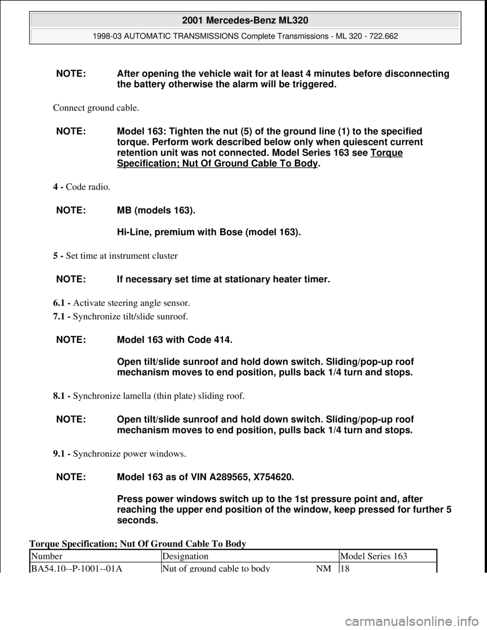
Connect ground cable.
4 - Code radio.
5 - Set time at instrument cluster
6.1 - Activate steering angle sensor.
7.1 - Synchronize tilt/slide sunroof.
8.1 - Synchronize lamella (thin plate) sliding roof.
9.1 - Synchronize power windows.
Torque Specification; Nut Of Ground Cable To Body NOTE: After opening the vehicle wait for at least 4 minutes before disconnecting
the battery otherwise the alarm will be triggered.
NOTE: Model 163: Tighten the nut (5) of the ground line (1) to the specified
torque. Perform work described below only when quiescent current
retention unit was not connected. Model Series 163 see Torque
Specification; Nut Of Ground Cable To Body.
NOTE: MB (models 163).
Hi-Line, premium with Bose (model 163).
NOTE: If necessary set time at stationary heater timer.
NOTE: Model 163 with Code 414.
Open tilt/slide sunroof and hold down switch. Sliding/pop-up roof
mechanism moves to end position, pulls back 1/4 turn and stops.
NOTE: Open tilt/slide sunroof and hold down switch. Sliding/pop-up roof
mechanism moves to end position, pulls back 1/4 turn and stops.
NOTE: Model 163 as of VIN A289565, X754620.
Press power windows switch up to the 1st pressure point and, after
reaching the upper end position of the window, keep pressed for further 5
seconds.
NumberDesignationModel Series 163
BA54.10--P-1001--01ANut of ground cable to bodyNM18
2001 Mercedes-Benz ML320
1998-03 AUTOMATIC TRANSMISSIONS Complete Transmissions - ML 320 - 722.662
me
Saturday, October 02, 2010 3:15:25 PMPage 15 © 2006 Mitchell Repair Information Company, LLC.
Page 1489 of 4133
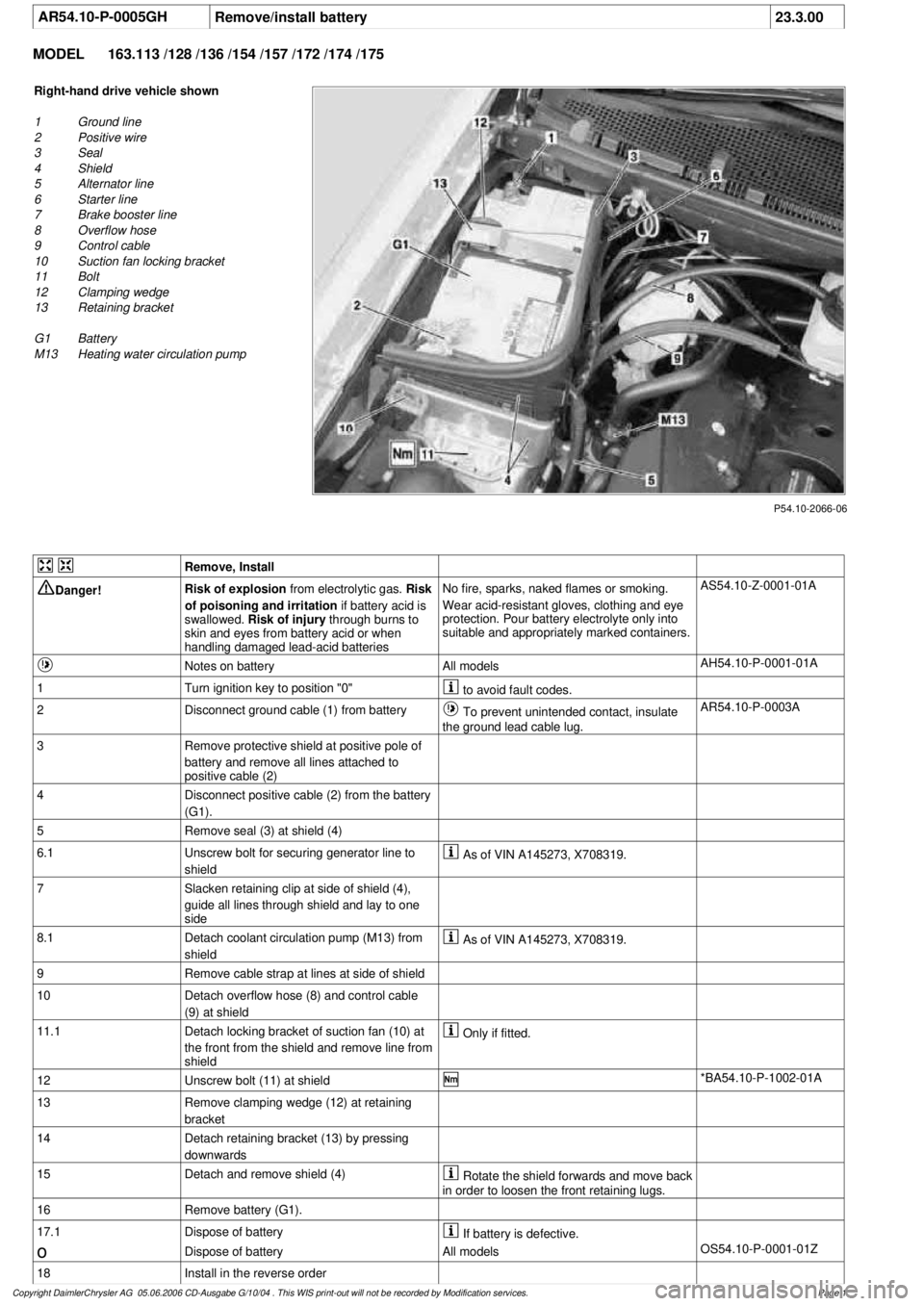
AR54.10-P-0005GH
Remove/install battery
23.3.00
MODEL
163.113 /128 /136 /154 /157 /172 /174 /175
P54.10-2066-06
Right-hand drive vehicle shown
1
Ground line
2
Positive wire
3
Seal
4
Shield
5
Alternator line
6
Starter line
7
Brake booster line
8
Overflow hose
9
Control cable
10
Suction fan locking bracket
11
Bolt
12
Clamping wedge
13
Retaining bracket
G1 Battery
M13
Heating water circulation pump
Remove, Install
Danger!
Risk of explosion
from electrolytic gas.
Risk
of poisoning and irritation
if battery acid is
swallowed.
Risk of injury
through burns to
skin and eyes from battery acid or when
handling damaged lead-acid batteries
No fire, sparks, naked flames or smoking.
Wear acid-resistant gloves, clothing and eye
protection. Pour battery electrolyte only into
suitable and appropriately marked containers.
AS54.10-Z-0001-01A
Notes on battery
All models
AH54.10-P-0001-01A
1
Turn ignition key to position "0"
to avoid fault codes.
2
Disconnect ground cable (1) from battery
To prevent unintended contact, insulate
the ground lead cable lug.
AR54.10-P-0003A
3
Remove protective shield at positive pole of
battery and remove all lines attached to
positive cable (2)
4
Disconnect positive cable (2) from the battery
(G1).
5
Remove seal (3) at shield (4)
6.1
Unscrew bolt for securing generator line to
shield
As of VIN A145273, X708319.
7
Slacken retaining clip at side of shield (4),
guide all lines through shield and lay to one
side
8.1
Detach coolant circulation pump (M13) from
shield
As of VIN A145273, X708319.
9
Remove cable strap at lines at side of shield
10
Detach overflow hose (8) and control cable
(9) at shield
11.1
Detach locking bracket of suction fan (10) at
the front from the shield and remove line from
shield
Only if fitted.
12
Unscrew bolt (11) at shield
*BA54.10-P-1002-01A
13
Remove clamping wedge (12) at retaining
bracket
14
Detach retaining bracket (13) by pressing
downwards
15
Detach and remove shield (4)
Rotate the shield forwards and move back
in order to loosen the front retaining lugs.
16
Remove battery (G1).
17.1
Dispose of battery
If battery is defective.
o
Dispose of battery
All models
OS54.10-P-0001-01Z
18
Install in the reverse order
Copyright DaimlerChrysler AG 05.06.2006 CD-Ausgabe G/10/04 . This WIS print-out will not be recorde
d by Modification services.
Page 1
Page 1490 of 4133
Battery
Number
Designation
Model
Series 163
BA54.10-P-1002-01A
Bolt of shield to body
Nm
20
Copyright DaimlerChrysler AG 05.06.2006 CD-Ausgabe G/10/04 . This WIS print-out will not be recorde
d by Modification services.
Page 2
Page 1631 of 4133
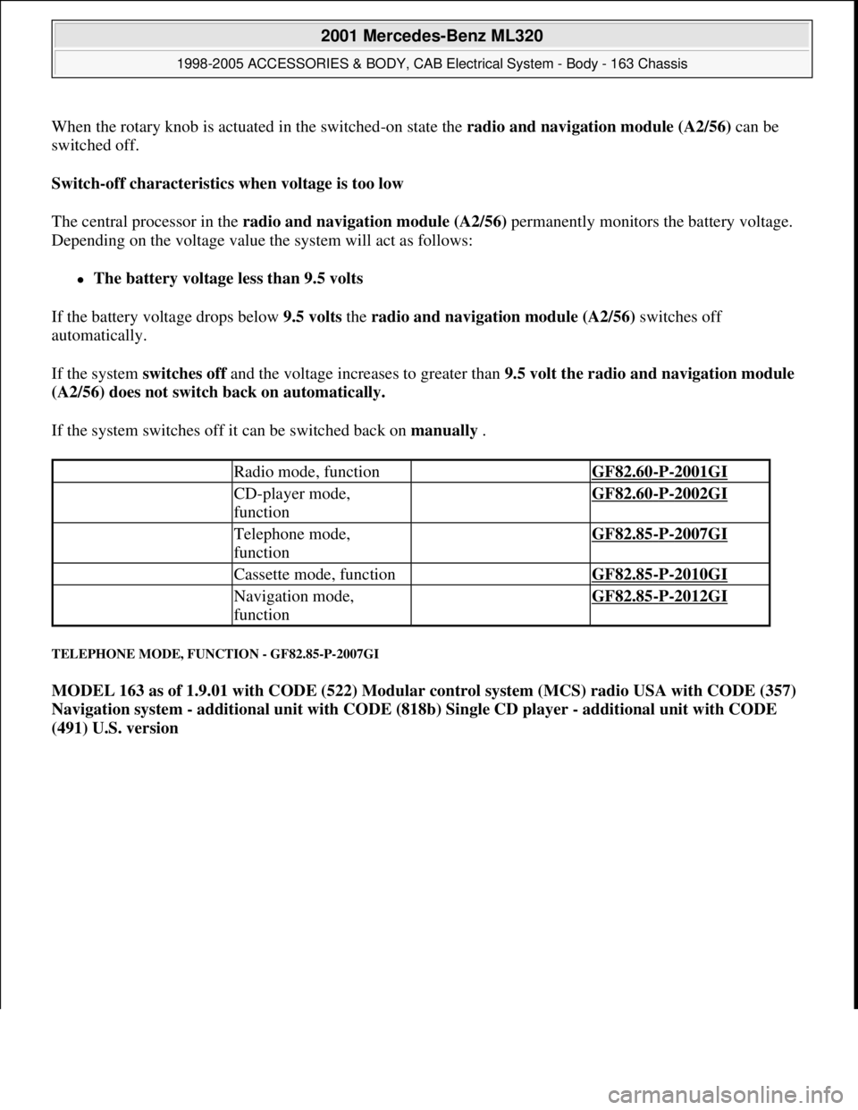
When the rotary knob is actuated in the switched-on state the radio and navigation module (A2/56)can be
switched off.
Switch-off characteristics when voltage is too low
The central processor in the radio and navigation module (A2/56) permanently monitors the battery voltage.
Depending on the voltage value the system will act as follows:
The battery voltage less than 9.5 volts
If the battery voltage drops below 9.5 volts the radio and navigation module (A2/56) switches off
automatically.
If the system switches off and the voltage increases to greater than 9.5 volt the radio and navigation module
(A2/56) does not switch back on automatically.
If the system switches off it can be switched back on manually .
TELEPHONE MODE, FUNCTION - GF82.85-P-2007GI
MODEL 163 as of 1.9.01 with CODE (522) Modular control system (MCS) radio USA with CODE (357)
Navigation system - additional unit with CODE (818b) Single CD player - additional unit with CODE
(491) U.S. version
Radio mode, function GF82.60-P-2001GI
CD-player mode,
function GF82.60-P-2002GI
Telephone mode,
function GF82.85-P-2007GI
Cassette mode, function GF82.85-P-2010GI
Navigation mode,
function GF82.85-P-2012GI
2001 Mercedes-Benz ML320
1998-2005 ACCESSORIES & BODY, CAB Electrical System - Body - 163 Chassis
me
Saturday, October 02, 2010 3:30:06 PMPage 136 © 2006 Mitchell Repair Information Company, LLC.
Page 1683 of 4133
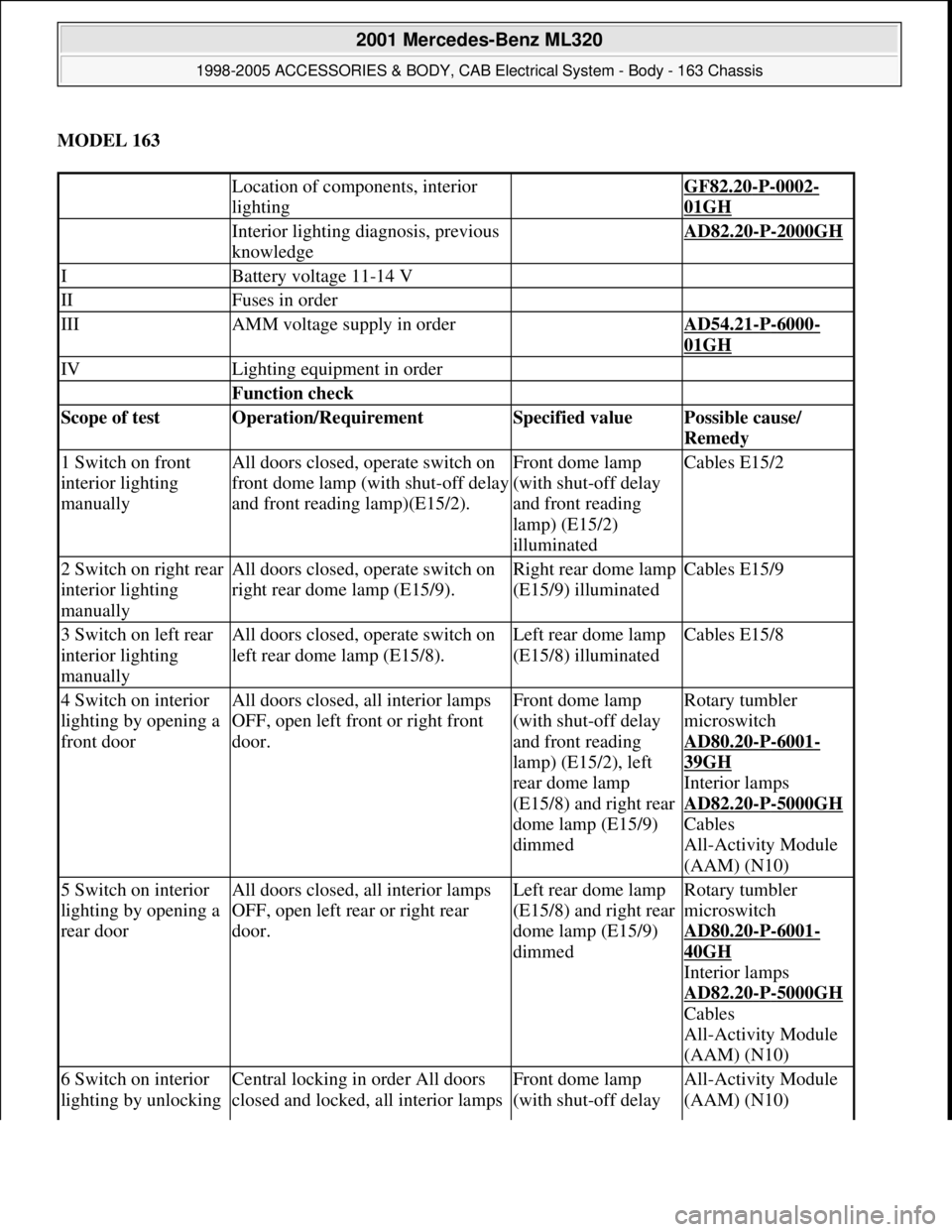
MODEL 163
Location of components, interior
lighting GF82.20-P-0002-
01GH
Interior lighting diagnosis, previous
knowledge AD82.20-P-2000GH
IBattery voltage 11-14 V
IIFuses in order
IIIAMM voltage supply in order AD54.21-P-6000-
01GH
IVLighting equipment in order
Function check
Scope of test Operation/Requirement Specified value Possible cause/
Remedy
1 Switch on front
interior lighting
manuallyAll doors closed, operate switch on
front dome lamp (with shut-off delay
and front reading lamp)(E15/2).Front dome lamp
(with shut-off delay
and front reading
lamp) (E15/2)
illuminatedCables E15/2
2 Switch on right rear
interior lighting
manuallyAll doors closed, operate switch on
right rear dome lamp (E15/9).Right rear dome lamp
(E15/9) illuminatedCables E15/9
3 Switch on left rear
interior lighting
manuallyAll doors closed, operate switch on
left rear dome lamp (E15/8).Left rear dome lamp
(E15/8) illuminatedCables E15/8
4 Switch on interior
lighting by opening a
front doorAll doors closed, all interior lamps
OFF, open left front or right front
door.Front dome lamp
(with shut-off delay
and front reading
lamp) (E15/2), left
rear dome lamp
(E15/8) and right rear
dome lamp (E15/9)
dimmedRotary tumbler
microswitch
AD80.20
-P-6001-
39GH
Interior lamps
AD82.20
-P-5000GH
Cables
All-Activity Module
(AAM) (N10)
5 Switch on interior
lighting by opening a
rear doorAll doors closed, all interior lamps
OFF, open left rear or right rear
door.Left rear dome lamp
(E15/8) and right rear
dome lamp (E15/9)
dimmedRotary tumbler
microswitch
AD80.20
-P-6001-
40GH
Interior lamps
AD82.20
-P-5000GH
Cables
All-Activity Module
(AAM) (N10)
6 Switch on interior
lighting by unlocking Central locking in order All doors
closed and locked, all interior lamps Front dome lamp
(with shut-off delay All-Activity Module
(AAM) (N10)
2001 Mercedes-Benz ML320
1998-2005 ACCESSORIES & BODY, CAB Electrical System - Body - 163 Chassis
me
Saturday, October 02, 2010 3:30:07 PMPage 188 © 2006 Mitchell Repair Information Company, LLC.
Page 1684 of 4133
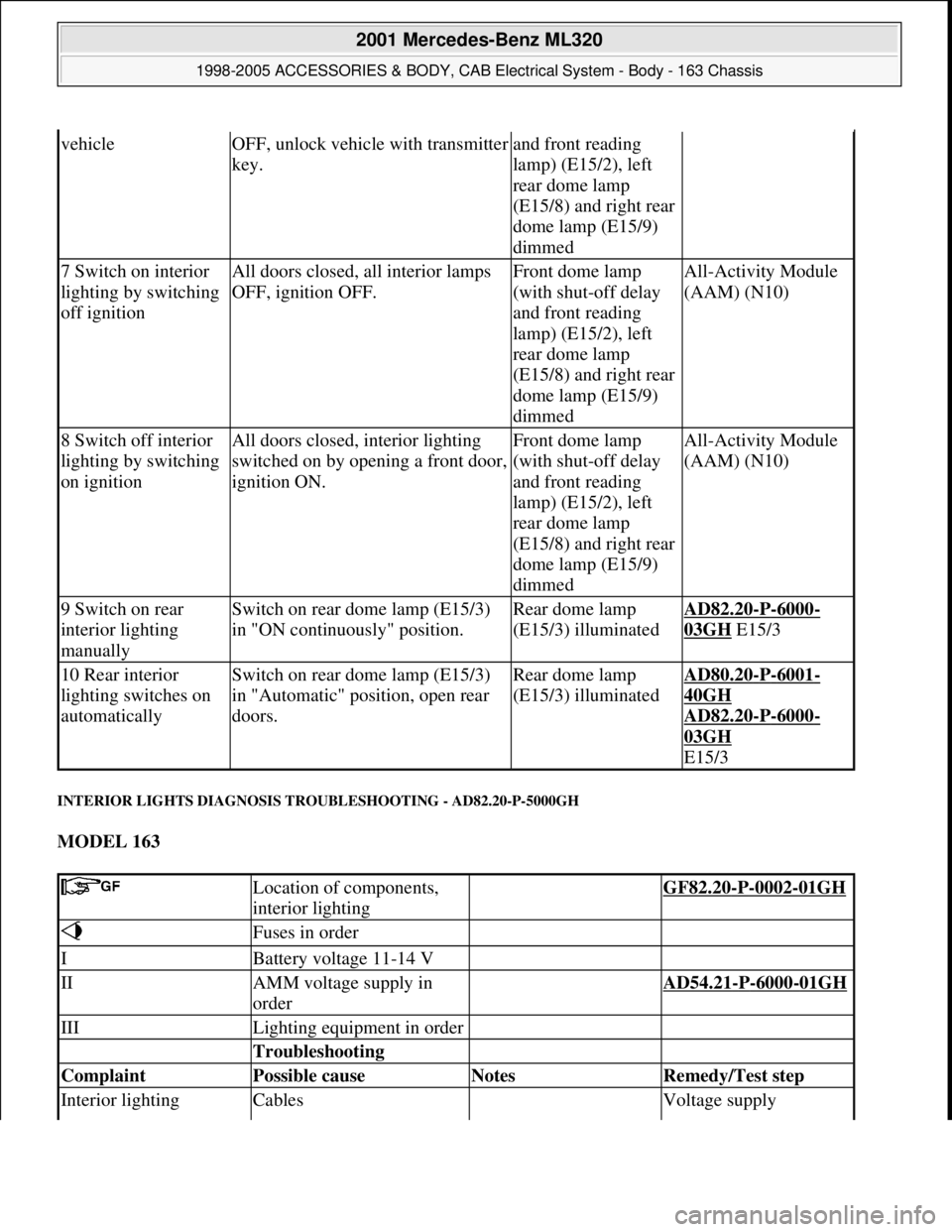
INTERIOR LIGHTS DIAGNOSIS TROUBLESHOOTING - AD82.20-P-5000GH
MODEL 163
vehicleOFF, unlock vehicle with transmitter
key.and front reading
lamp) (E15/2), left
rear dome lamp
(E15/8) and right rear
dome lamp (E15/9)
dimmed
7 Switch on interior
lighting by switching
off ignitionAll doors closed, all interior lamps
OFF, ignition OFF.Front dome lamp
(with shut-off delay
and front reading
lamp) (E15/2), left
rear dome lamp
(E15/8) and right rear
dome lamp (E15/9)
dimmedAll-Activity Module
(AAM) (N10)
8 Switch off interior
lighting by switching
on ignitionAll doors closed, interior lighting
switched on by opening a front door,
ignition ON.Front dome lamp
(with shut-off delay
and front reading
lamp) (E15/2), left
rear dome lamp
(E15/8) and right rear
dome lamp (E15/9)
dimmedAll-Activity Module
(AAM) (N10)
9 Switch on rear
interior lighting
manuallySwitch on rear dome lamp (E15/3)
in "ON continuously" position.Rear dome lamp
(E15/3) illuminatedAD82.20-P-6000-
03GH E15/3
10 Rear interior
lighting switches on
automaticallySwitch on rear dome lamp (E15/3)
in "Automatic" position, open rear
doors.Rear dome lamp
(E15/3) illuminatedAD80.20-P-6001-
40GH
AD82.20
-P-6000-
03GH
E15/3
Location of components,
interior lighting GF82.20-P-0002-01GH
Fuses in order
IBattery voltage 11-14 V
IIAMM voltage supply in
order AD54.21-P-6000-01GH
IIILighting equipment in order
Troubleshooting
Complaint Possible cause Notes Remedy/Test step
Interior lighting Cables Voltage supply
2001 Mercedes-Benz ML320
1998-2005 ACCESSORIES & BODY, CAB Electrical System - Body - 163 Chassis
me
Saturday, October 02, 2010 3:30:07 PMPage 189 © 2006 Mitchell Repair Information Company, LLC.