1997 MERCEDES-BENZ ML430 relay
[x] Cancel search: relayPage 1116 of 4133

312 Technical termsEngine oil viscosity
Measurement for the inner friction (vis-
cosity) of the oil at different tempera-
tures. The higher the temperature an
oil can tolerate without becoming thin,
or the lower the temperature it can tol-
erate without becoming viscous, the
better the viscosity.
ESP
(E
lectronic S
tability Pr
ogram)
Improves vehicle handling and direc-
tional stability.
ETD
(E
mergency T
ensioning D
evice)
Device which deploys in certain frontal
and rear collisions exceeding the sys-
tem's threshold to tighten the seat
belts.
->SRSFSS
(F
lexible S
ervice S
ystem)
Service indicator in the speedometer
display that informs the driver when
the next vehicle maintenance service is
due.
Gear range
Number of gears which are available to
the automatic transmission for shifting.
The automatic gear shifting process
can be adapted to specific operating
conditions using the gear selector
lever.
GPS
(G
lobal P
ositioning S
ystem)
Satellite-based system for relaying
geographic location information to and
from vehicles equipped with special re-
ceivers. Employs CD or DVD digital
maps for navigation.GAWR
(G
ross A
xle W
eight R
ating)
The GAWR is the maximum permissible
axle weight. The gross vehicle weight
on each axle must never exceed the
GAWR for the front and rear axle indi-
cated on the certification label located
on the driver’s door pillar.
GVW
(G
ross V
ehicle W
eight)
The GVW comprises the weight of the
vehicle including fuel, tools, spare
wheel, installed accessories, passen-
gers and cargo. The GVW must never
exceed the GVWR, indicated on the
certification label located on the driv-
er’s door pillar.
Page 1149 of 4133
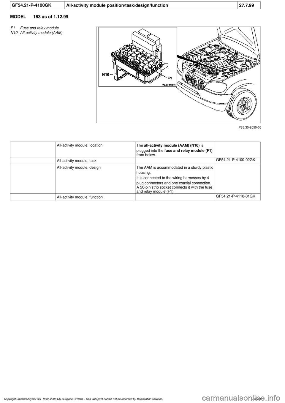
GF54.21-P-4100GK
All-activity module position/task/design/function
27.7.99
MODEL
163 as of 1.12.99
P83.30-2050-05
F1
Fuse and relay module
N10
All-activity module (AAM)
All-activity module, location
The
all-activity module (AAM) (N10)
is
plugged into the
fuse and relay module (F1)
from below.
All-activity module, task
GF54.21-P-4100-02GK
All-activity module, design
The AAM is accommodated in a sturdy plastic
housing.
It is connected to the wiring harnesses by 4
plug connectors and one coaxial connection.
A 50-pin strip socket connects it with the fuse
and relay module (F1).
All-activity module, function
GF54.21-P-4110-01GK
Copyright DaimlerChrysler AG 18.05.2006 CD-Ausgabe G/10/04 . This WIS print-out will not be recorde
d by Modification services.
Page 1
Page 1150 of 4133

GF54.30-P-3010A
Function of acoustic warnings
24.10.96
MODEL
129, 140 as of 1.6.96,
163, 168, 170,
202 as of 1.8.96,
208 up to 31.7.99,
210 as of 1.6.96 up to 30.6.99
Display
Function
Turn signal indicator
ticking
Switching on the turn signal indicator is
indicated acoustically by the turn signal
indicator ticking. The driver's attention is
brought to a defect in the turn signal system
by the turn signal indicator ticking at a higher
frequency.
Turn signal indicator ticking is generated
electromagnetically. The frequency
corresponds to that of the turn signal indicator
lamp.
The signal comes from the combination relay
(turn signal indicator with trailer coupling, rear
window defroster), wiper motor, ATA (N10/2),
on model 210 from the multi-function control
module (N10-1) or from the driver-side signal-
acquisition and actuation module (SAM)
(N10/1), on model 163 from the All-Activity
Module (AAM, N10), on model 168 it is
generated by the integrated turn signal
indicator control in the instrument cluster (A1).
Parking brake reminderThe parking brake warning sounds when
terminal 15g is ON from a speed of approx. 5
km/h.
Piezoelectric loudspeaker (quartz), function
GF54.30-P-3017A
Gear warning, model 168
only with automatic
transmission or automatic
clutch
The acoustic gear warning is active, when
D
a gear is engaged
and
D
the brake is
not
depressed
and
D
the accelerator pedal is
not
pressed
and
D
the driver's door is opened.
These conditions are processed in the gear
recognition module (A61) or in the automatic
clutch control module (N15/4). The
information on the status of the driver's door
is available as a CAN message. It is
transmitted by the instrument cluster (A1).
Piezoelectric loudspeaker (quartz), function
GF54.30-P-3017A
Speed warning
The speed warning sounds when terminal
15g is ON from a speed of approx. 120 km/h.
(on national variants only)
Piezoelectric loudspeaker (quartz), function
GF54.30-P-3017A
Speed limit warning
The warning sounds if the set maximum
speed is exceeded by at least 6 km/h.
(on vehicles with variable cruise control only)
Piezoelectric loudspeaker (quartz), function
GF54.30-P-3017A
Seat belt reminder
On national variants only
Piezoelectric loudspeaker (quartz), function
GF54.30-P-3017A
Switched-on lights
reminder
The switched-on lights reminder sounds when
terminal 15g is OFF, terminal 58k is ON,
when the starter key is removed and the
driver's door is opened.
Piezoelectric loudspeaker (quartz), function
GF54.30-P-3017A
Key reminder
The key reminder when terminal 15g is OFF
and the driver's door is open when the starter
key is inserted
Piezoelectric loudspeaker (quartz), function
GF54.30-P-3017A
Soft top reminder, model
170 only
The soft top reminder sounds when terminal
15 is ON and soft top reminder input is on low
level.
Piezoelectric loudspeaker (quartz), function
GF54.30-P-3017A
Copyright DaimlerChrysler AG 05.06.2006 CD-Ausgabe G/10/04 . This WIS print-out will not be recorde
d by Modification services.
Page 1
Page 1169 of 4133
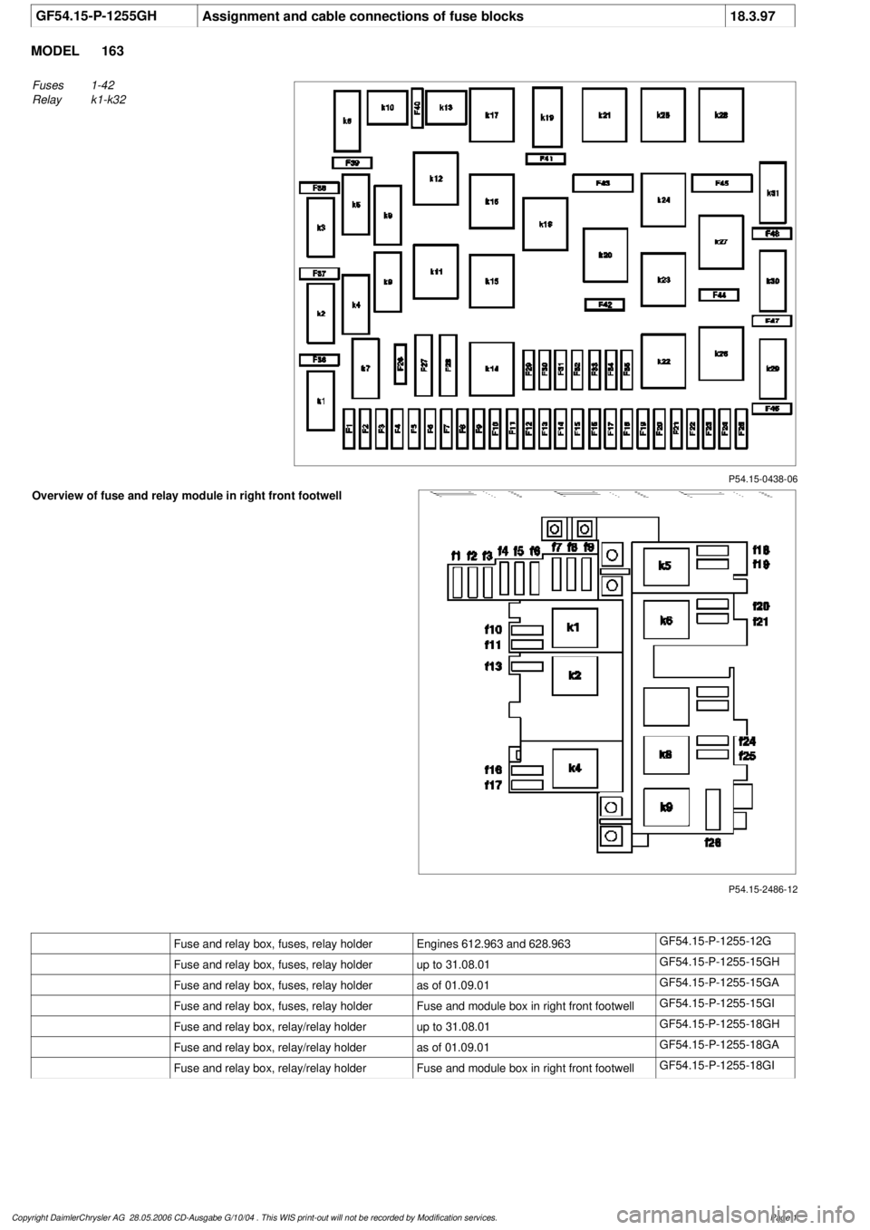
GF54.15-P-1255GH
Assignment and cable connections of fuse blocks
18.3.97
MODEL
163
P54.15-0438-06
Fuses
1-42
Relay
k1-k32
P54.15-2486-12
Overview of fuse and relay module in right front footwell
Fuse and relay box, fuses, relay holder
Engines 612.963 and 628.963
GF54.15-P-1255-12G
Fuse and relay box, fuses, relay holder
up to 31.08.01
GF54.15-P-1255-15GH
Fuse and relay box, fuses, relay holder
as of 01.09.01
GF54.15-P-1255-15GA
Fuse and relay box, fuses, relay holder
Fuse and module box in right front footwell
GF54.15-P-1255-15GI
Fuse and relay box, relay/relay holder
up to 31.08.01
GF54.15-P-1255-18GH
Fuse and relay box, relay/relay holder
as of 01.09.01
GF54.15-P-1255-18GA
Fuse and relay box, relay/relay holder
Fuse and module box in right front footwell
GF54.15-P-1255-18GI
Copyright DaimlerChrysler AG 28.05.2006 CD-Ausgabe G/10/04 . This WIS print-out will not be recorde
d by Modification services.
Page 1
Page 1523 of 4133
![MERCEDES-BENZ ML430 1997 Complete Repair Manual Function prerequisites:
Circuit 15 ON
Function
The headlamp cleaning system is switched on by pressing the SRA [HCS] switch (S4/1) .
The corresponding input of the Extended Activity M MERCEDES-BENZ ML430 1997 Complete Repair Manual Function prerequisites:
Circuit 15 ON
Function
The headlamp cleaning system is switched on by pressing the SRA [HCS] switch (S4/1) .
The corresponding input of the Extended Activity M](/manual-img/4/57307/w960_57307-1522.png)
Function prerequisites:
Circuit 15 ON
Function
The headlamp cleaning system is switched on by pressing the SRA [HCS] switch (S4/1) .
The corresponding input of the Extended Activity Module (EAM) (N10/1) , which receives the input
from the switch, sends the signal to relay 5 (F2k5) .
The relay switches circuit 30 , for a duty cycle of approx. 1 second, through to the HCS pump (M5/2) .
The HCS pump (M5/2) builds up pressure in the washing water line.
The water pressure acts against the return springs of the telescopic nozzles.
The telescopic nozzles extend and spray washing water onto the headlamp glass.
After the duty cycle, the pressure in the washing water line drops again and the telescopic nozzles move
back to their starting position due to spring load.
Pressing the SRA [HCS] switch (S4/1) again during an ongoing headlamp cleaning cycle has no effect.
A further cleaning cycle can only be initiated after the previous cycle has ended.
TABLE OF CONTENTS, FUNCTION DESCRIPTION FOR HEADLAMP CLEANING SYSTEM (HCS) - GF82.15-P-0998GHZ
MODEL 163 as of 01.09.01 with CODE (600a) headlamp cleaning system
FUNCTION OF HEADLAMP CLEANING SYSTEM TELESCOPIC NOZZLES - GF82.15-P-2100-04GH
After the HCS pump (M5/2) has started to operate, pressure builds up in the washing water line for approx. 1
Headlamp cleaning system (HCS),
location of components GF82.15-P-0002-
03GH
Telescopic nozzles for headlamp
cleaning system,
location/task/design/function GF82.15-P-2100GH
Extended Activity Module,
location/task/design GF54.21-P-4107GK
Headlamp cleaning system
(HCS), function GF82.15-P-0002GH
Headlamp cleaning system
(HCS), location of components GF82.15-P-0002-
03GH
Survey of system components
for headlamp cleaning system
(HCS), location/task/design/
function GF82.15-P-9998GHZ
2001 Mercedes-Benz ML320
1998-2005 ACCESSORIES & BODY, CAB Electrical System - Body - 163 Chassis
me
Saturday, October 02, 2010 3:30:04 PMPage 28 © 2006 Mitchell Repair Information Company, LLC.
Page 1537 of 4133
REAR INTERMITTENT WIPE - FUNCTION - GF82.30-P-3001GH
MODEL 163 Applicable to 31.8.00
The rear intermittent wipe function is activated by placing the rear wiper/washer switch (S78) in the up
position. With the switch in this position, the All Activity Module (AAM) (N10) activates the tailgate wiper
motor (M6/4) every five seconds.
A relay circuit in the wiper motor stops the wiper arm in the park position.
REAR INTERMITTENT WIPE - FUNCTION - GF82.30-P-3001GK
MODEL 163 Applicable as of 1.9.00
The rear intermittent wipe function is linked, among other things, to the operation of the windshield wiper
system. It will therefore be described in relation to the position of the combination switch (S4):
Combination switch (S4) position: OFF
The rear wiper is powered from KI. 15R: ON by operating the rear wiper/washer switch (S78) . Switching
on the wiper illuminates the LED on the rear wiper/washer switch (S78) and immediately causes the wiper arm
to perform one complete sweep before switching to intermittent wiping.
When the vehicle is traveling at speeds of
less than 100 km/h the wipe interval is 10 seconds
of 100 km/h or more the wipe interval is 5 seconds .
The wiper is turned off by reactivating the wiper/washer switch.
Combination switch (S4) position: Wiper speed 1 or 2
The rear wiper is activated from KI. 15R: ON using the rear wiper/washer switch (S78) .
Switching on the wiper illuminates the LED on the rear wiper/ washer switch (S78) and immediately
causes the wiper arm to perform one complete sweep before switching to intermittent wiping. The wipe
interval is 5 seconds .
Survey on wiper system
components (WS), location/
purpose/design/function GF82.30-P-9998GH
Rear wiper/washer switch GF82.30-P-4105GH
All Activity ModuleTo 30.11.99GF54.21-P-4100GH
As of 1.12.99GF54.21-P-4100GK
Tailgate wiper motor GF82.30-P-4105GH
2001 Mercedes-Benz ML320
1998-2005 ACCESSORIES & BODY, CAB Electrical System - Body - 163 Chassis
me
Saturday, October 02, 2010 3:30:04 PMPage 42 © 2006 Mitchell Repair Information Company, LLC.
Page 1539 of 4133
The actual frequency is also a factor of the vehicle's speed of travel (see chart below).
The wiper is turned off by reactivating the wiper/washer switch.
The start of each wipe cycle is synchronized with the front wiper system.
Networking
Rain sensor (B38) and reverse signals are fed to the All Activity Module (AAM) (N10) via the engine
compartment CAN.
The settings of the rear wiper/washer switch (S78) are read directly by the All Activity Module (AAM)
(N10) .
The tailgate wiper motor unit (M6/4) is controlled directly by the All Activity Module (AAM, N10) .
The tailgate wiper motor unit (M6/4) comprises a relay and a cam-operated switch in addition to the
actual motor.
WINDSHIELD INTERMITTENT WIPE, FUNCTION - GF82.30-P-3003GH
MODEL 163
Function sequence
The interval wiping function is switched on to position (i) with the combination switch.
The input (pin A8) of the all-activity module (AAM, N10) is connected to c. 15 R .
The AAM immediately actuates the front wiper motor relay (F1k17) for max. 2 s. In wiper stage 1 power is
supplied to the wiper motor (M6/1) b
y the relay (pin a).
Vehicle speed Under 50
km/hVehicle speed 50 to 100
km/hVehicle speed 100 km/h
and higher
Frequency of Rear wiperOne twelfth of front
wiper frequencyOne tenth of front wiper
frequencyOne sixth of front wiper
frequency
Rear Wiper/Washer Switch -
Location/Task/ Design/Function GF82.30-P-
4105GH
All Activity Module -
Location/Task/Design/ Function GF54.21-P-
4100GK
Tailgate Wiper Motor -
Location/Task/Design/ Function GF82.30-P-
4105GH
Rain Sensor -
Location/Task/Design/FunctionVehicles with code
345a (rain sensor)
onlyGF82.30-P-
4103GH
2001 Mercedes-Benz ML320
1998-2005 ACCESSORIES & BODY, CAB Electrical System - Body - 163 Chassis
me
Saturday, October 02, 2010 3:30:04 PMPage 44 © 2006 Mitchell Repair Information Company, LLC.
Page 1540 of 4133
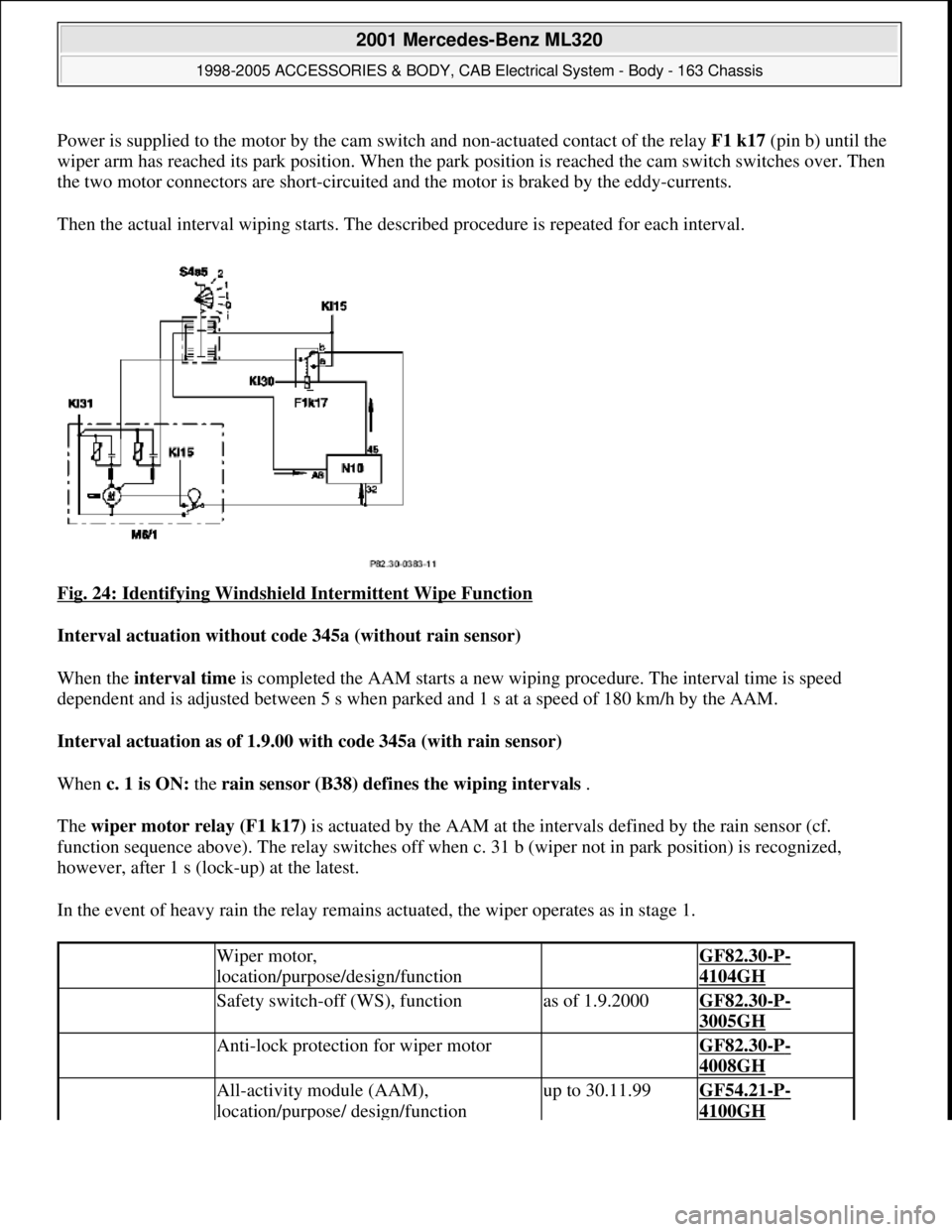
Power is supplied to the motor by the cam switch and non-actuated contact of the relay F1 k17(pin b) until the
wiper arm has reached its park position. When the park position is reached the cam switch switches over. Then
the two motor connectors are short-circuited and the motor is braked by the eddy-currents.
Then the actual interval wiping starts. The described procedure is repeated for each interval.
Fig. 24: Identifying Windshield Intermittent Wipe Function
Interval actuation without code 345a (without rain sensor)
When the interval time is completed the AAM starts a new wiping procedure. The interval time is speed
dependent and is adjusted between 5 s when parked and 1 s at a speed of 180 km/h by the AAM.
Interval actuation as of 1.9.00 with code 345a (with rain sensor)
When c. 1 is ON: the rain sensor (B38) defines the wiping intervals .
The wiper motor relay (F1 k17) is actuated by the AAM at the intervals defined by the rain sensor (cf.
function sequence above). The relay switches off when c. 31 b (wiper not in park position) is recognized,
however, after 1 s (lock-up) at the latest.
In the event of heavy rain the relay remains actuated, the wiper operates as in stage 1.
Wiper motor,
location/purpose/design/function GF82.30-P-
4104GH
Safety switch-off (WS), functionas of 1.9.2000GF82.30-P-
3005GH
Anti-lock protection for wiper motor GF82.30-P-
4008GH
All-activity module (AAM),
location/purpose/ design/functionup to 30.11.99GF54.21-P-
4100GH
2001 Mercedes-Benz ML320
1998-2005 ACCESSORIES & BODY, CAB Electrical System - Body - 163 Chassis
me
Saturday, October 02, 2010 3:30:04 PMPage 45 © 2006 Mitchell Repair Information Company, LLC.