1997 MERCEDES-BENZ ML430 relay
[x] Cancel search: relayPage 1541 of 4133
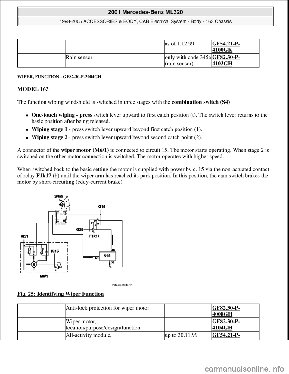
WIPER, FUNCTION - GF82.30-P-3004GH
MODEL 163
The function wiping windshield is switched in three stages with the combination switch (S4)
One-touch wiping - press switch lever upward to first catch position (t). The switch lever returns to the
basic position after being released.
Wiping stage 1 - press switch lever upward beyond first catch position (1).
Wiping stage 2 - press switch lever upward beyond second catch point (2).
A connector of the wiper motor (M6/1) is connected to circuit 15. The motor starts operating. When stage 2 is
switched on the other motor connection is switched. The motor operates with higher speed.
When switched back to the basic setting the motor is supplied with power by c. 15 via the non-actuated contact
of relay F1k17 (b) until the wiper arm has reached its park position. In this position, the cam switch brakes the
motor by short-circuiting (eddy-current brake)
Fig. 25: Identifying Wiper Function
as of 1.12.99GF54.21-P-
4100GK
Rain sensoronly with code 345a
(rain sensor)GF82.30-P-
4103GH
Anti-lock protection for wiper motor GF82.30-P-
4008GH
Wiper motor,
location/purpose/design/function GF82.30-P-
4104GH
All-activity module, up to 30.11.99GF54.21-P-
2001 Mercedes-Benz ML320
1998-2005 ACCESSORIES & BODY, CAB Electrical System - Body - 163 Chassis
me
Saturday, October 02, 2010 3:30:04 PMPage 46 © 2006 Mitchell Repair Information Company, LLC.
Page 1542 of 4133
SAFETY SHUTOFF (WSA) - FUNCTION - GF82.30-P-3005GH
MODEL 163 Applicable as of 1.9.00
Safety shutoff
The intermittent wipe function is interrupted when the vehicle comes to a complete stop and at least one of
the front doors is open. Any wipe cycle in progress is completed before wipers come to a halt.
Wiping resumes when both front doors are closed and/or the vehicle is put into motion.
The safety shutoff therefore only operates when the vehicle is at a complete stop. This ensures that the
intermittent wiping feature remains available during driving even if a door jamb switch is defective.
ANTI-LOCK PROTECTION FOR WIPER MOTOR, FUNCTION - GF82.30-P-4008GH
MODEL 163
The all-activity module(AAM) (N10) recognizes that the wiper motor (M6/1) is locked up because of the
absence of signals from the cam switch.
If signals are not recognized for longer than 1 s the front wiper motor relay (F1k17) is no longer actuated.
The anti-lock protection is only effective in the function interval wiping . In other wiper stages the AAM does
not have influence on the wiper motor.
RAIN SENSOR - FUNCTION - GF82.30-P-4103-02GH
location/purpose/design/function4100GH
as of 1.12.99GF54.21-P-
4100GK
Extended activity module,
location/purposeas of 1.12.99GF54.21-P-
4106GH
Windshield Intermittent
Wipe - Function GF82.30-P-3003GH
Wiper motor,
location/purpose/design/function GF82.30-P-
4104GH
All-activity module (AAM),
location/purpose/ design/functionup to 30.11.99GF54.21-P-
4100GH
as of 1.12.99GF54.21-P-
4100GK
2001 Mercedes-Benz ML320
1998-2005 ACCESSORIES & BODY, CAB Electrical System - Body - 163 Chassis
me
Saturday, October 02, 2010 3:30:04 PMPage 47 © 2006 Mitchell Repair Information Company, LLC.
Page 1547 of 4133
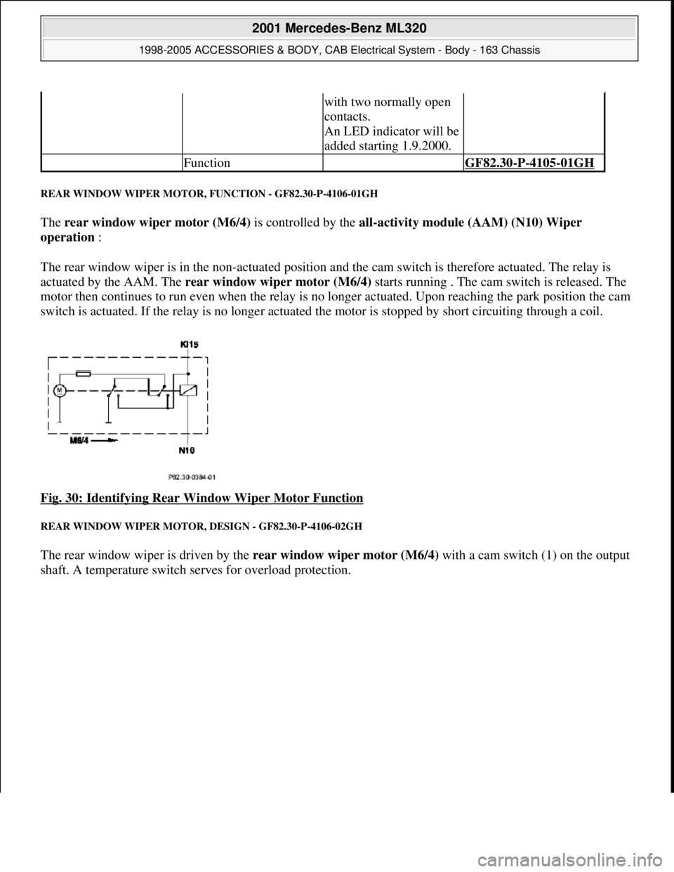
REAR WINDOW WIPER MOTOR, FUNCTION - GF82.30-P-4106-01GH
The rear window wiper motor (M6/4) is controlled by the all-activity module (AAM) (N10) Wiper
operation :
The rear window wiper is in the non-actuated position and the cam switch is therefore actuated. The relay is
actuated by the AAM. The rear window wiper motor (M6/4) starts running . The cam switch is released. The
motor then continues to run even when the relay is no longer actuated. Upon reaching the park position the cam
switch is actuated. If the relay is no longer actuated the motor is stopped by short circuiting through a coil.
Fig. 30: Identifying Rear Window Wiper Motor Function
REAR WINDOW WIPER MOTOR, DESIGN - GF82.30-P-4106-02GH
The rear window wiper is driven by the rear window wiper motor (M6/4) with a cam switch (1) on the output
shaft. A temperature switch serves for overload protection.
with two normally open
contacts.
An LED indicator will be
added starting 1.9.2000.
Function GF82.30-P-4105-01GH
2001 Mercedes-Benz ML320
1998-2005 ACCESSORIES & BODY, CAB Electrical System - Body - 163 Chassis
me
Saturday, October 02, 2010 3:30:05 PMPage 52 © 2006 Mitchell Repair Information Company, LLC.
Page 1549 of 4133
REAR WASH - FUNCTION - GF82.35-P-3001GH
MODEL 163
The rear wash function is activated by placing the rear wiper/ washer switch (S78) in the down position. The
switch contact connects the tailgate washer pump (M5/3) to terminal 15. The All Activity Module (AAM)
(N10) detects the activation of the switch via the second switch contact and actuates the tailgate washer motor
(M6/4) and the tailgate washer fluid pump (M5/3) for as long as the switch is on.
The activation time for the tailgate washer fluid pump (M5/3)is limited to 15 sec. To reactivate the pump, the
button must be pressed again.
To wipe window dry, the tailgate wiper motor (M6/4) remains activated for five seconds after the switch is
released.
As described for the rear wiper function, a relay circuit in the wiper motor stops the wiper in the park position .
WINDSHIELD WASH - FUNCTION - GF82.35-P-3002GH
MODEL 163
The windshield wash function is activated by pulling the combination switch, washer switch (S4s4) towards
the steering column. The switch contact connects the washer pump (M5/1) to terminal 15R. The All Activity
Module (AAM) (N10) detects switch activation via an input that measures power supply to the washer pump
(M5/1).
If the combination switch (S4) is in the Wiper Off or Intermittent position, the AAM activates the wiper
motor (M6/1) via rela
y F1k17 . To wipe windshield dry, the motor continues to operate after the switch has
Rear window washer
pump, location /
purpose / design /
function GF82.35-P-4103GH
Table of contents,
function description,
wiper system (WS) GF82.30-P-0998GH
Rear Wipe GF82.30-P-3004GH
Rear Wiper/Washer
Switch GF82.30-P-4105GH
Tailgate Wiper Motor GF82.30-P-4106GH
Tailgate Washer Pump GF82.35-P-4103GH
All Activity ModuleTo 30.11.99GF54.21-P-4100GH
As of 1.12.99GF54.21-P-4100GK
2001 Mercedes-Benz ML320
1998-2005 ACCESSORIES & BODY, CAB Electrical System - Body - 163 Chassis
me
Saturday, October 02, 2010 3:30:05 PMPage 54 © 2006 Mitchell Repair Information Company, LLC.
Page 1556 of 4133
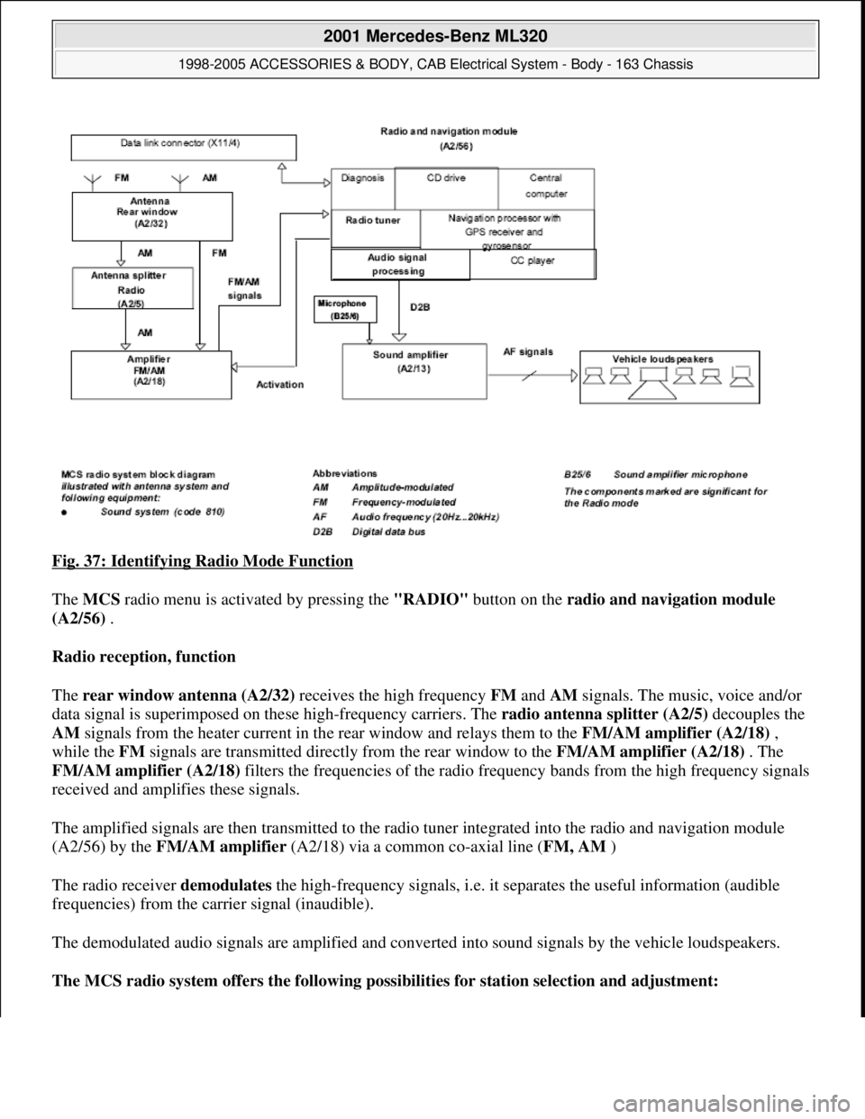
Fig. 37: Identifying Radio Mode Function
The MCS radio menu is activated by pressing the "RADIO" button on the radio and navigation module
(A2/56) .
Radio reception, function
The rear window antenna (A2/32) receives the high frequency FM and AM signals. The music, voice and/or
data signal is superimposed on these high-frequency carriers. The radio antenna splitter (A2/5) decouples the
AM signals from the heater current in the rear window and relays them to the FM/AM amplifier (A2/18) ,
while the FM signals are transmitted directly from the rear window to the FM/AM amplifier (A2/18) . The
FM/AM amplifier (A2/18) filters the frequencies of the radio frequency bands from the high frequency signals
received and amplifies these signals.
The amplified signals are then transmitted to the radio tuner integrated into the radio and navigation module
(A2/56) by the FM/AM amplifier (A2/18) via a common co-axial line (FM, AM )
The radio receiver demodulates the high-frequency signals, i.e. it separates the useful information (audible
frequencies) from the carrier signal (inaudible).
The demodulated audio signals are amplified and converted into sound signals by the vehicle loudspeakers.
The MCS radio system offers the following possibilities for station selection and adjustment:
2001 Mercedes-Benz ML320
1998-2005 ACCESSORIES & BODY, CAB Electrical System - Body - 163 Chassis
me
Saturday, October 02, 2010 3:30:05 PMPage 61 © 2006 Mitchell Repair Information Company, LLC.
Page 1597 of 4133
DVD drive and DVD
The DVD drive of the radio (A2) reads data from the navigation DVD inserted and makes this available to the
navigation processor via the data bus inside the device.
Audio CDs can also be played.
The following are located on the navigation DVD:
Program data for the navigation computer
Voice segments for voice output
Map data.
A distinction is made between digitized and non-digitized areas within the DVD map area:
Villages, towns, roads, intersections and their attributes (e.g. one-way streets, no turns etc.) are recorded
in the digitized map area.
Included in the non-digitized areas are, for example company/private grounds, farms, small housing
estates, tracks across fields and areas between villages.
No data is available here.
Diagnosis interface (K-line) and fault management of D2B-components
During operation, the system stores all occurring faults in the nonvolatile memory. It is not possible to output
the fault via the display of the radio (A2).
The radio's (A2) fault management also includes the D2B-components connected. For this purpose, each D2B
component has its own DTC memory. The faults are transmitted from the corresponding components via the
D2B to the radio (A2) and can then be read out via the diagnosis interface
RADIO AND NAVIGATION MODULE, FUNCTION - GF82.61-P-4109-04GI
Processing button actuations
The control buttons and switches on the function keypad on the radio and navigation module (A2/56)are read
in via the I/O ports of the microcontroller and transferred to the central processor. Depending on the system
function the button actuations are processed in the central processor or relayed to the other system components
via the digital data bus ( D2B ) in form of a data telegram.
Graphic preparation and image output
The graphics subsystem handles the preparation and output of the operating displays. The operating displays are
output internally to the display by the graphic subsystem via the RGB output ( R =red, G =green, B =blue).
The RGB signal contains information and amplitudes of the three basic colors Red, G reen and Blue as well
2001 Mercedes-Benz ML320
1998-2005 ACCESSORIES & BODY, CAB Electrical System - Body - 163 Chassis
me
Saturday, October 02, 2010 3:30:05 PMPage 102 © 2006 Mitchell Repair Information Company, LLC.
Page 1632 of 4133
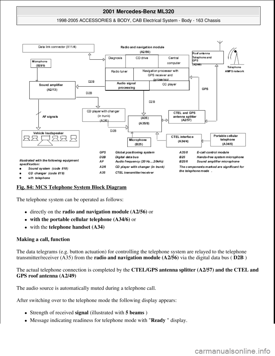
Fig. 84: MCS Telephone System Block Diagram
The telephone system can be operated as follows:
directly on the radio and navigation module (A2/56) or
with the portable cellular telephone (A34/6) or
with the telephone handset (A34)
Making a call, function
The data telegrams (e.g. button actuation) for controlling the telephone system are relayed to the telephone
transmitter/receiver (A35) from the radio and navigation module (A2/56) via the digital data bus ( D2B )
The actual telephone connection is completed by the CTEL/GPS antenna splitter (A2/57) and the CTEL and
GPS roof antenna (A2/49)
The audio source is automatically muted during a telephone call.
After switching over to the telephone mode the following display appears:
Strength of received signal (illustrated with 5 beams )
Message indicating readiness for telephone mode with "Ready" display.
2001 Mercedes-Benz ML320
1998-2005 ACCESSORIES & BODY, CAB Electrical System - Body - 163 Chassis
me
Saturday, October 02, 2010 3:30:06 PMPage 137 © 2006 Mitchell Repair Information Company, LLC.
Page 1690 of 4133
Location of components,
wiper systemFront screen&(GF82.30-P-0005-
01GH)
Rear screen&(GF82.30-P-0004-
01GH)
Battery voltage 11-14 V
Fuses in order
AAM voltage supply in
order AD54.21-P-6000-01GH
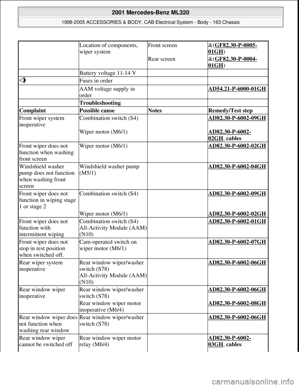
Troubleshooting
Complaint Possible cause Notes Remedy/Test step
Front wiper system
inoperativeCombination switch (S4) AD82.30-P-6002-09GH
Wiper motor (M6/1) AD82.30-P-6002-
02GH, cables
Front wiper does not
function when washing
front screenWiper motor (M6/1) AD82.30-P-6002-02GH
Windshield washer
pump does not function
when washing front
screenWindshield washer pump
(M5/1) AD82.30-P-6002-04GH
Front wiper does not
function in wiping stage
1 or stage 2Combination switch (S4) AD82.30-P-6002-09GH
Wiper motor (M6/1) AD82.30-P-6002-02GH
Front wiper does not
function with
intermittent wipingCombination switch (S4)
All-Activity Module (AAM)
(N10) AD82.30-P-6002-01GH
Front wiper does not
stop in rest position
when switched off.Cam-operated switch on
wiper motor (M6/1) AD82.30-P-6002-07GH
Rear wiper system
inoperativeRear window wiper/washer
switch (S78)
All-Activity Module (AAM)
(N10) AD82.30-P-6002-06GH
Rear window wiper
inoperativeRear window wiper/washer
switch (S78) AD82.30-P-6002-06GH
Rear window wiper motor
inoperative (M6/4) AD82.30-P-6002-08GH
Rear window wiper does
not function when
washing rear windowRear window wiper/washer
switch (S78) AD82.30-P-6002-06GH
Rear window wiper
cannot be switched offRear window wiper motor
relay (M6/4) AD82.30-P-6002-
03GH, cables
2001 Mercedes-Benz ML320
1998-2005 ACCESSORIES & BODY, CAB Electrical System - Body - 163 Chassis
me
Saturday, October 02, 2010 3:30:07 PMPage 195 © 2006 Mitchell Repair Information Company, LLC.