Page 2400 of 4133
Fig. 34: Identifying Motor Electronics Control Module - Shown On Model 163.154
Shown on Model 163.154
Fig. 35: Identifying Connector Of Engine Compartment And Engine
- Shown On Model 163.154
Shown on Model 163.154
Remove/Install
1Disconnect ground of battery
(W10)
Installation: After connecting, read out fault memory,
encode radio and normalize power windows.
Vehicles with stationary he ater: adjust time display on
stationary heater.
AR54.10-
P-0003A
2Remove cover of fuse module
(1)
3Remove cover of relay module
(2)
Remove electronics ground of
2001 Mercedes-Benz ML320
1998-2005 ENGINE Complete engine - 163 Chassis
me
Saturday, October 02, 2010 3:17:56 PMPage 44 © 2006 Mitchell Repair Information Company, LLC.
Page 2401 of 4133
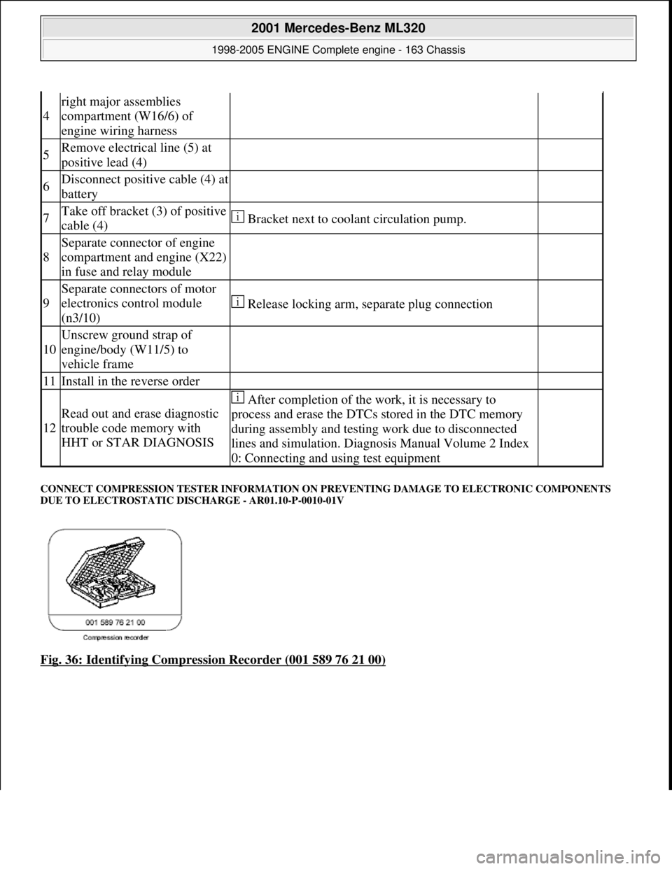
CONNECT COMPRESSION TESTER INFORMATION ON PR EVENTING DAMAGE TO ELECTRONIC COMPONENTS
DUE TO ELECTROSTATIC DI SCHARGE - AR01.10-P-0010-01V
Fig. 36: Identifying Compression Recorder (001 589 76 21 00)
4
right major assemblies
compartment (W16/6) of
engine wiring harness
5Remove electrical line (5) at
positive lead (4)
6Disconnect positive cable (4) at
battery
7Take off bracket (3) of positive
cable (4) Bracket next to coolant circulation pump.
8
Separate connector of engine
compartment and engine (X22)
in fuse and relay module
9
Separate connectors of motor
electronics control module
(n3/10)
Release locking arm, separate plug connection
10
Unscrew ground strap of
engine/body (W11/5) to
vehicle frame
11Install in the reverse order
12
Read out and erase diagnostic
trouble code memory with
HHT or STAR DIAGNOSIS
After completion of the work, it is necessary to
process and erase the DTCs stored in the DTC memory
during assembly and testing work due to disconnected
lines and simulation. Diagnosis Manual Volume 2 Index
0: Connecting and using test equipment
2001 Mercedes-Benz ML320
1998-2005 ENGINE Complete engine - 163 Chassis
me
Saturday, October 02, 2010 3:17:56 PMPage 45 © 2006 Mitchell Repair Information Company, LLC.
Page 2402 of 4133
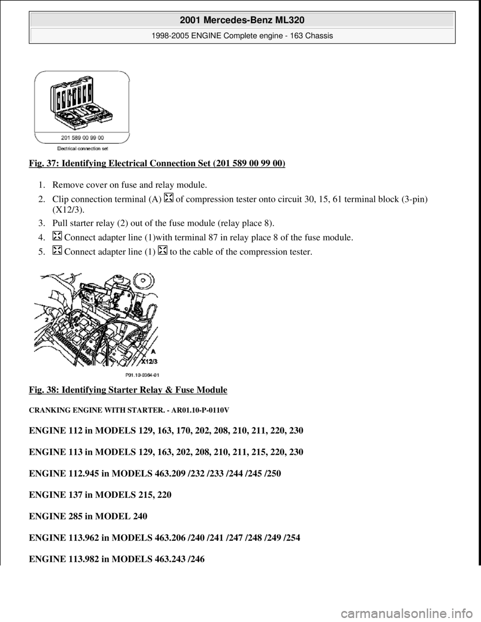
Fig. 37: Identifying Electrical Connection Set (201 589 00 99 00)
1. Remove cover on fuse and relay module.
2. Clip connection terminal (A) of compression tester onto circuit 30, 15, 61 terminal block (3-pin)
(X12/3).
3. Pull starter relay (2) out of the fuse module (relay place 8).
4. Connect adapter line (1)w ith terminal 87 in relay place 8 of the fuse module.
5. Connect adapter line (1) to the cable of the compression tester.
Fig. 38: Identifying Star ter Relay & Fuse Module
CRANKING ENGINE WITH STARTER. - AR01.10-P-0110V
ENGINE 112 in MODELS 129, 163, 170, 202, 208, 210, 211, 220, 230
ENGINE 113 in MODELS 129, 163, 202, 208, 210, 211, 215, 220, 230
ENGINE 112.945 in MODELS 463.209 /232 /233 /244 /245 /250
ENGINE 137 in MODELS 215, 220
ENGINE 285 in MODEL 240
ENGINE 113.962 in MODELS 463.206 / 240 /241 /247 /248 /249 /254
ENGINE 113.982 in MODELS 463.243 /246
2001 Mercedes-Benz ML320
1998-2005 ENGINE Complete engine - 163 Chassis
me
Saturday, October 02, 2010 3:17:56 PMPage 46 © 2006 Mitchell Repair Information Company, LLC.
Page 2516 of 4133
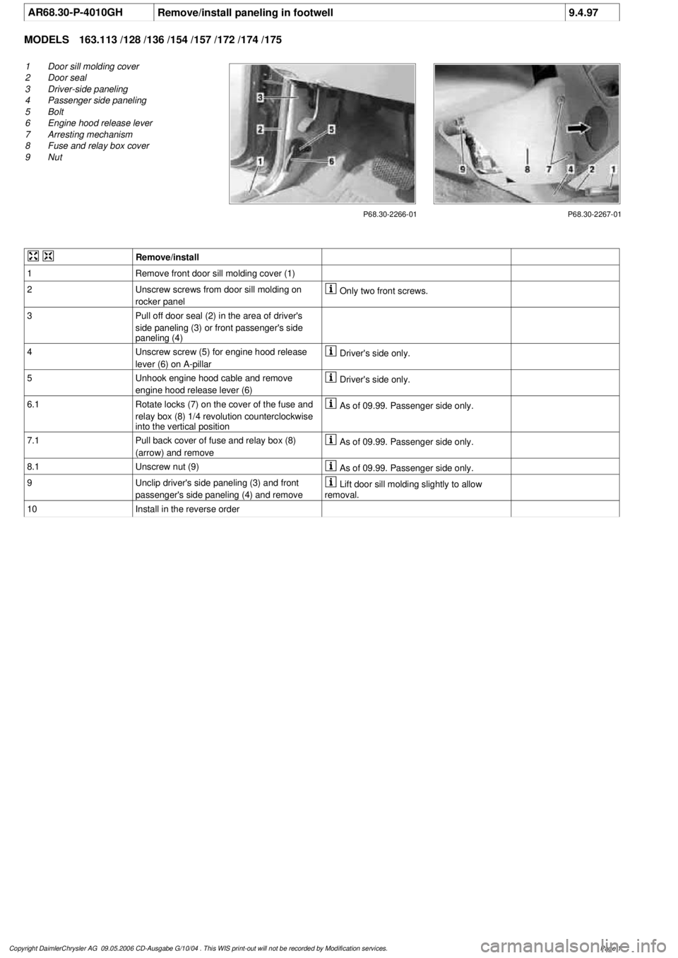
AR68.30-P-4010GHRemove/install paneling in footwell
9.4.97
MODELS
163.113 /128 /136 /154 /157 /172 /174 /175
P68.30-2266-01
1
Door sill molding cover
2
Door seal
3
Driver-side paneling
4
Passenger side paneling
5
Bolt
6
Engine hood release lever
7
Arresting mechanism
8
Fuse and relay box cover
9
Nut
P68.30-2267-01
Remove/install
1
Remove front door sill molding cover (1)
2
Unscrew screws from door sill molding on
rocker panel
Only two front screws.
3
Pull off door seal (2) in the area of driver's
side paneling (3) or front passenger's side
paneling (4)
4
Unscrew screw (5) for engine hood release
lever (6) on A-pillar
Driver's side only.
5
Unhook engine hood cable and remove
engine hood release lever (6)
Driver's side only.
6.1
Rotate locks (7) on the cover of the fuse and
relay box (8) 1/4 revolution counterclockwise
into the vertical position
As of 09.99. Passenger side only.
7.1
Pull back cover of fuse and relay box (8)
(arrow) and remove
As of 09.99. Passenger side only.
8.1
Unscrew nut (9)
As of 09.99. Passenger side only.
9
Unclip driver's side paneling (3) and front
passenger's side paneling (4) and remove
Lift door sill molding slightly to allow
removal.
10
Install in the reverse order
Copyright DaimlerChrysler AG 09.05.2006 CD-Ausgabe G/10/04 . This WIS print-out will not be recorde
d by Modification services.
Page 1
Page 2606 of 4133
AR47.10-P-4001GH
Emptying, filling the fuel tank
11.3.97
Model
163.136 with engine 111.977
Model
163.154 with engine 112.942
Model
163.157 with engine 112.970
Model
163.172 with engine 113.942
Model
163.174 with engine 113.981
Model
163.175 with engine 113.965
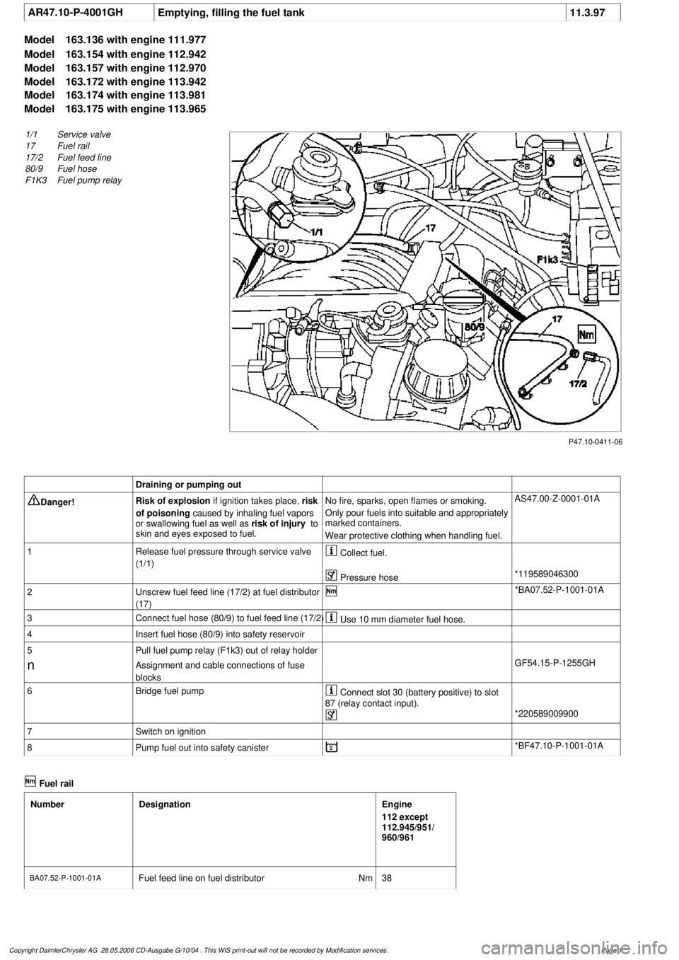
P47.10-0411-06
1/1
Service valve
17
Fuel rail
17/2
Fuel feed line
80/9
Fuel hose
F1K3
Fuel pump relay
Draining or pumping out
Danger!
Risk of explosion
if ignition takes place,
risk
of poisoning
caused by inhaling fuel vapors
or swallowing fuel as well as
risk of injury
to
skin and eyes exposed to fuel.
No fire, sparks, open flames or smoking.
Only pour fuels into suitable and appropriately
marked containers.
Wear protective clothing when handling fuel.
AS47.00-Z-0001-01A
1
Release fuel pressure through service valve
(1/1)
Collect fuel.
Pressure hose
*119589046300
2
Unscrew fuel feed line (17/2) at fuel distributor
(17)
*BA07.52-P-1001-01A
3
Connect fuel hose (80/9) to fuel feed line (17/2)
Use 10 mm diameter fuel hose.
4
Insert fuel hose (80/9) into safety reservoir
5
Pull fuel pump relay (F1k3) out of relay holder
n
Assignment and cable connections of fuse
blocks
GF54.15-P-1255GH
6
Bridge fuel pump
Connect slot 30 (battery positive) to slot
87 (relay contact input).
*220589009900
7
Switch on ignition
8
Pump fuel out into safety canister
*BF47.10-P-1001-01A
Fuel rail
Number
Designation
Engine
112 except
112.945/951/
960/961
BA07.52-P-1001-01A
Fuel feed line on fuel distributor
Nm
38
Copyright DaimlerChrysler AG 28.05.2006 CD-Ausgabe G/10/04 . This WIS print-out will not be recorde
d by Modification services.
Page 1
Page 2615 of 4133
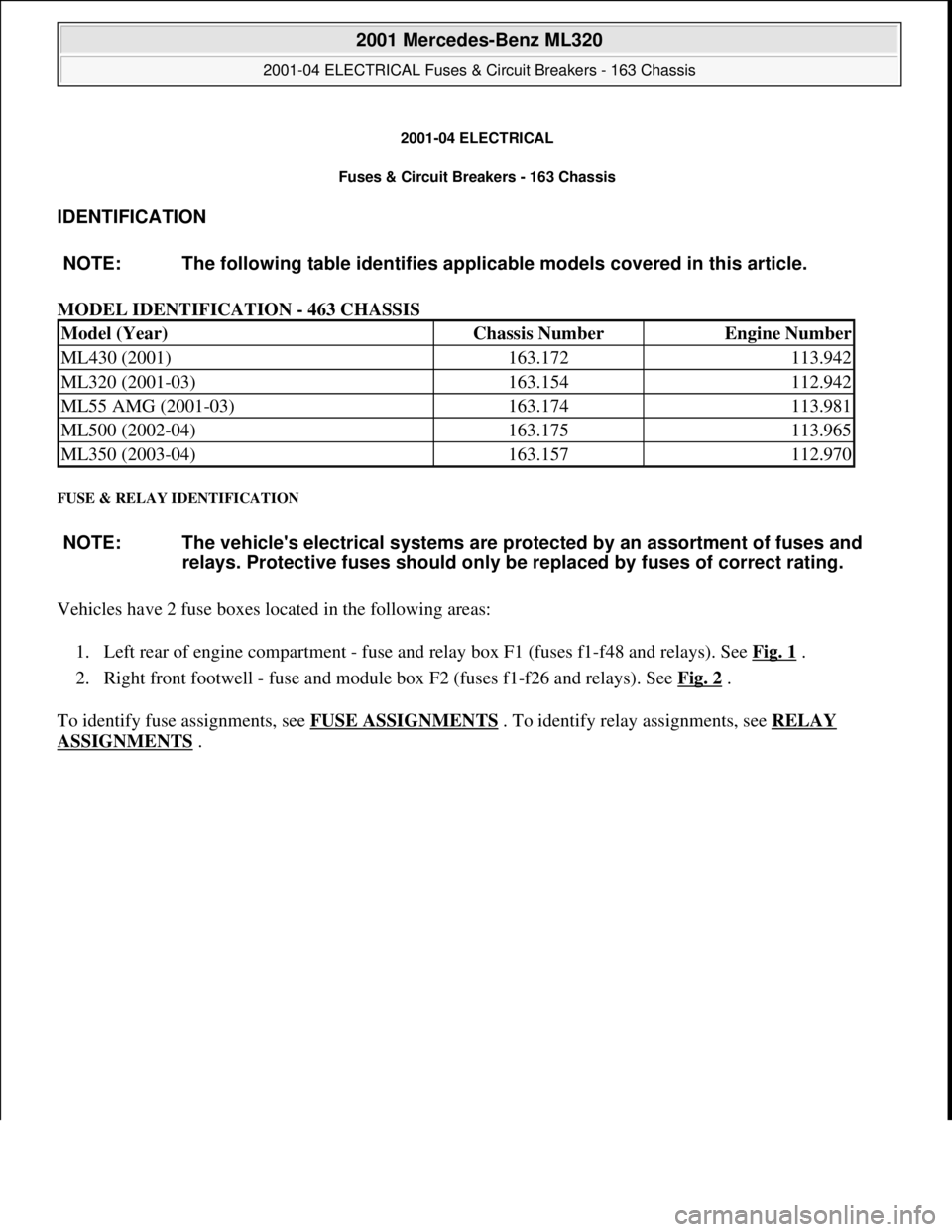
2001-04 ELECTRICAL
Fuses & Circuit Breakers - 163 Chassis
IDENTIFICATION
MODEL IDENTIFICATION - 463 CHASSIS
FUSE & RELAY IDENTIFICATION
Vehicles have 2 fuse boxes located in the following areas:
1. Left rear of engine compartment - fuse and relay box F1 (fuses f1-f48 and relays). See Fig. 1
.
2. Right front footwell - fuse and module box F2 (fuses f1-f26 and relays). See Fig. 2
.
To identify fuse assignments, see FUSE ASSIGNMENTS
. To identify relay assignments, see RELAY
ASSIGNMENTS . NOTE: The following table identifies applicable models covered in this article.
Model (Year)Chassis NumberEngine Number
ML430 (2001)163.172113.942
ML320 (2001-03)163.154112.942
ML55 AMG (2001-03)163.174113.981
ML500 (2002-04)163.175113.965
ML350 (2003-04)163.157112.970
NOTE: The vehicle's electrical systems are protected by an assortment of fuses and
relays. Protective fuses should only be replaced by fuses of correct rating.
2001 Mercedes-Benz ML320
2001-04 ELECTRICAL Fuses & Circuit Breakers - 163 Chassis
2001 Mercedes-Benz ML320
2001-04 ELECTRICAL Fuses & Circuit Breakers - 163 Chassis
me
Saturday, October 02, 2010 3:22:06 PMPage 1 © 2006 Mitchell Repair Information Company, LLC.
me
Saturday, October 02, 2010 3:22:09 PMPage 1 © 2006 Mitchell Repair Information Company, LLC.
Page 2616 of 4133
Fig. 1: Locating Fuse & Relay Box F1
Courtesy of MERCEDES-BENZ OF NORTH AMERICA.
2001 Mercedes-Benz ML320
2001-04 ELECTRICAL Fuses & Circuit Breakers - 163 Chassis
me
Saturday, October 02, 2010 3:22:06 PMPage 2 © 2006 Mitchell Repair Information Company, LLC.
Page 2617 of 4133
Fig. 2: Locating Fuse & Module Box F2
Courtesy of MERCEDES-BENZ OF NORTH AMERICA.
FUSE ASSIGNMENTS
Fuse & Relay Box F1 Fuse Assignments (Up-To-08/31/01)
For fuse locations, see Fig. 3 . For fuse assignments, see Fig. 4-Fig. 9.
2001 Mercedes-Benz ML320
2001-04 ELECTRICAL Fuses & Circuit Breakers - 163 Chassis
me
Saturday, October 02, 2010 3:22:06 PMPage 3 © 2006 Mitchell Repair Information Company, LLC.