1997 MERCEDES-BENZ ML430 relay
[x] Cancel search: relayPage 2067 of 4133

GF72.29-P-2002GH
Convenience control, function
7.4.97
MODEL
163
The convenience control allows the driver to operate the electrical
seat adjustment, the power windows, the electric vent windows, the
electric outside rearview mirror as well as the electric sliding/pop-up
roof or the electric lamella sliding roof
when the ignition is switched
off.
To achieve this, the all-activity module (AAM) (N10) switches to the
corresponding loads via the convenience relay (F1k14)
circuit 30 .
As of 12.99 the vehicle is equipped with its own convenience relay for
seat adjustment (relay 1, F2k1). In addition the status of the
convenience control via CAN is transmitted to the extended activity
module (EAM, N10/1).
Conditions for control actuation
On all-activity module (AAM) (N10) configured for
I
up
to
11.99:
The convenience actuation becomes active as soon as
D
Circuit 15 ON is recognized
When circuit 15 is switched off, the convenience actuation is
deactivated after a door is opened
Otherwise
The convenience actuation is active in the following cases:
D
Circuit 15c ON
D
A front door is open
D
The remote control key is removed, however, the doors are not
yet opened
In both cases the convenience actuation remains active for 5 min.
Switch-on condition for circuit 15c
When the remote control key is inserted into the ignition lock, circuit
15c is switched on when the key is turned out of the zero position.
Circuit 15c switches off only after the remote control key is removed
from the ignition lock
Electric seat adjustment without memory,
function
GF91.29-P-0003GH
Electric seat adjustment with memory, function
as of 12.99
GF91.29-P-0002GH
Convenience control, function
for electrical seat adjustment as of 12.99
GF91.29-P-2013GK
Power windows, function
GF72.29-P-0003GH
Power tilting/sliding roof (SR), function
GF77.20-P-0001GH
Electrically adjustable outside rearview
mirrors, function
GF88.79-P-0005GH
Electric vent windows, function
GF67.39-P-1000GH
Extended activity module,
location/purpose/design
as of 12.99
GF54.21-P-4107GK
Copyright DaimlerChrysler AG 04.08.2006 CD-Ausgabe G/10/04 . This WIS print-out will not be recorde
d by Modification services.
Page 1
Page 2139 of 4133

GF54.21-P-4106-01GH
Extended Activity Module - Task
n
The primary tasks of the Extended Activity Module (EAM, N10/1) are
as follows:
D
To control the door sill lights
D
To suppress the auto-dimming mirror function
D
To control the headlight cleaning system (HCS)
D
To control the rear window defroster
D
To control seat heating
D
To control the power supply via control console to tilt/sliding or
louvered sunroof switch
D
To control the PTC heater booster (R22/3)
D
To control the auxiliary fan (M4)
D
To read the cruise control switch (S40) and relay data to control
module (DAS, N73/1)
D
To read the contacts for wiper speed settings 1 and 2 on
combination switch (S4) for diagnosis.
To perform these tasks the Extended Activity Module (EAM, N10/1)
reads various signals and switch settings directly.
The Extended Activity Module (EAM, N10/1) interfaces with other
control modules via the engine compartment CAN.
-----------------------------------------------------------------------------------------
Diagnosis
Diagnosis is performed using the Star diagnostic tool. To facilitate
this task, the Extended Activity Module (EAM, N10/1) is equipped
with its own diagnostics cable.
This cable is also used to diagnose the
All Activity Module (AAM,
N10)
and the
transfer case control module (N78)
.
The Extended Activity Module (EAM, N10/1) is linked to the All
Activity Module (AAM, N10) via the
engine compartment CAN
.
Data communication between the All Activity Module (AAM,
N10) and the Extended Activity Module (EAM, N10/1) is
assumed by the
CAN (N10 - N10/1)
when terminal 15 is off.
The CAN (N10 - N10/1)
is an independent CAN bus located
between the All Activity Module (AAM, N10) and the Extended
Activity Module (EAM, N10/1).
No other
control modules are
connected to the CAN (N10 - N10/1).
-----------------------------------------------------------------------------------------
Details:
Door sill lights
When the front interior light is on and one of the front doors is open,
or when the rear interior light is on and one of the back doors is open,
the door sill lights for the open door will illuminate.
Headlight cleaning system (HCS)
Activating a separate switch causes the EAM to send a turn-on signal
to the HCS pump relay.
EAM will send an additional turn-on signal to the HCS pump relay
only after the cleaning operation is completed and a "rest period" of
approximately 2.5 sec. has passed.
Auto-dimming mirror function
The auto-dimming mirror function is suppressed when the interior
light is on or reverse gear is engaged.
Auto-dimming suppression for the outside rearview mirror (slave) is
activated by the inside rearview mirror (master).
Heater booster/PTC air heater for diesel engines
EAM monitors system voltage and adjusts heater booster capacity to
minimize load on battery.
Rear window defroster
EAM sets maximum ON time for rear window defroster depending
on outdoor temperature and current vehicle speed.
D
Standard ON time:
10 min.
D
Outdoor temperature < 5
o
C:
Additional 5 min.
D
Speed >80 km/h:
Additional 3 min.
Seat heating
Sets maximum seat heating time.
D
Setting 1: max. 20 min.
D
Setting 2: max. 5 min.
Tilt/sliding or louvered sunroofs
Signal via AAM2 allows operation of tilt/sliding or louvered sunroofs
when ignition is on (standard mode) or off (keyless mode).
Ignition authorization via CAN
The EAM issues ignition authorization to AAM2 via the engine
compartment CAN depending on the requirements of the engine
control unit in connection with the FBM.
Copyright DaimlerChrysler AG 18.05.2006 CD-Ausgabe G/10/04 . This WIS print-out will not be recorde
d by Modification services.
Page 1
Page 2141 of 4133
2001 MERCEDES-BENZ
ML320 & ML430
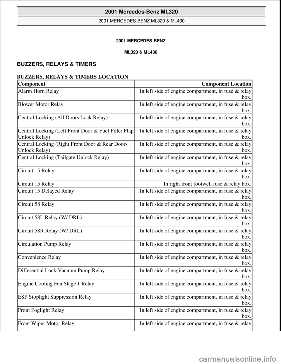
BUZZERS, RELAYS & TIMERS
BUZZERS, RELAYS & TIMERS LOCATION
ComponentComponent Location
Alarm Horn RelayIn left side of engine compartment, in fuse & relay
box.
Blower Motor RelayIn left side of engine compartment, in fuse & relay
box.
Central Locking (All Doors Lock Relay)In left side of engine compartment, in fuse & relay
box.
Central Locking (Left Front Door & Fuel Filler Flap
Unlock Relay)In left side of engine compartment, in fuse & relay
box.
Central Locking (Right Front Door & Rear Doors
Unlock Relay)In left side of engine compartment, in fuse & relay
box.
Central Locking (Tailgate Unlock Relay)In left side of engine compartment, in fuse & relay
box.
Circuit 15 RelayIn left side of engine compartment, in fuse & relay
box.
Circuit 15 RelayIn right front footwell fuse & relay box.
Circuit 15 Delayed RelayIn left side of engine compartment, in fuse & relay
box.
Circuit 58 RelayIn left side of engine compartment, in fuse & relay
box.
Circuit 58L Relay (W/ DRL)In left side of engine compartment, in fuse & relay
box.
Circuit 58R Relay (W/ DRL)In left side of engine compartment, in fuse & relay
box.
Circulation Pump RelayIn left side of engine compartment, in fuse & relay
box.
Convenience RelayIn left side of engine compartment, in fuse & relay
box.
Differential Lock Vacuum Pump RelayIn left side of engine compartment, in fuse & relay
box.
Engine Cooling Fan Stage 1 RelayIn left side of engine compartment, in fuse & relay
box.
ESP Stoplight Suppression RelayIn left side of engine compartment, in fuse & relay
box.
Front Foglight RelayIn left side of engine compartment, in fuse & relay
box.
Front Wiper Motor RelayIn left side of engine compartment, in fuse & relay
2001 Mercedes-Benz ML320
2001 MERCEDES-BENZ ML320 & ML430
2001 Mercedes-Benz ML320
2001 MERCEDES-BENZ ML320 & ML430
me
Saturday, October 02, 2010 3:21:17 PMPage 1 © 2006 Mitchell Repair Information Company, LLC.
me
Saturday, October 02, 2010 3:21:20 PMPage 1 © 2006 Mitchell Repair Information Company, LLC.
Page 2142 of 4133
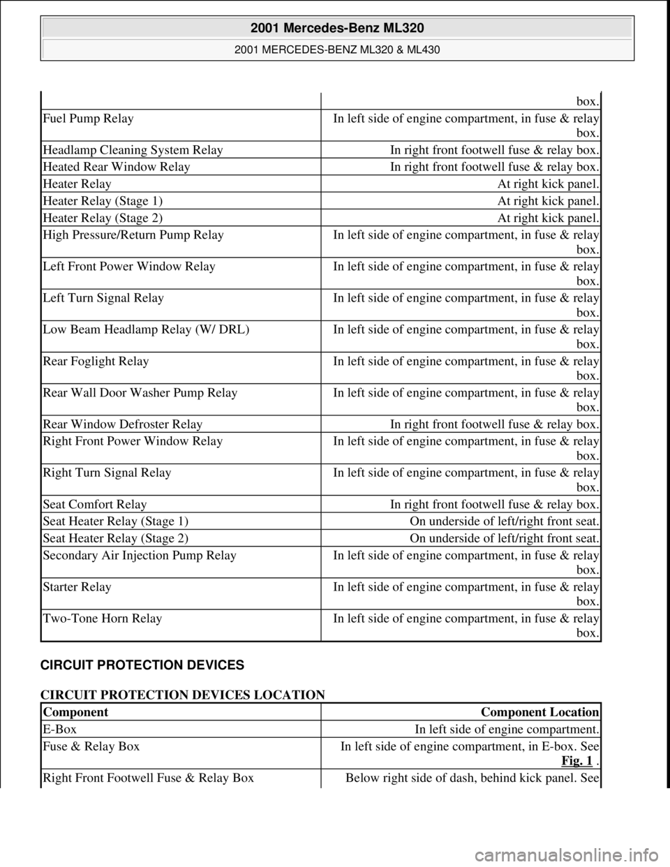
CIRCUIT PROTECTION DEVICES
CIRCUIT PROTECTION DEVICES LOCATION
box.
Fuel Pump RelayIn left side of engine compartment, in fuse & relay
box.
Headlamp Cleaning System RelayIn right front footwell fuse & relay box.
Heated Rear Window RelayIn right front footwell fuse & relay box.
Heater RelayAt right kick panel.
Heater Relay (Stage 1)At right kick panel.
Heater Relay (Stage 2)At right kick panel.
High Pressure/Return Pump RelayIn left side of engine compartment, in fuse & relay
box.
Left Front Power Window RelayIn left side of engine compartment, in fuse & relay
box.
Left Turn Signal RelayIn left side of engine compartment, in fuse & relay
box.
Low Beam Headlamp Relay (W/ DRL)In left side of engine compartment, in fuse & relay
box.
Rear Foglight RelayIn left side of engine compartment, in fuse & relay
box.
Rear Wall Door Washer Pump RelayIn left side of engine compartment, in fuse & relay
box.
Rear Window Defroster RelayIn right front footwell fuse & relay box.
Right Front Power Window RelayIn left side of engine compartment, in fuse & relay
box.
Right Turn Signal RelayIn left side of engine compartment, in fuse & relay
box.
Seat Comfort RelayIn right front footwell fuse & relay box.
Seat Heater Relay (Stage 1)On underside of left/right front seat.
Seat Heater Relay (Stage 2)On underside of left/right front seat.
Secondary Air Injection Pump RelayIn left side of engine compartment, in fuse & relay
box.
Starter RelayIn left side of engine compartment, in fuse & relay
box.
Two-Tone Horn RelayIn left side of engine compartment, in fuse & relay
box.
ComponentComponent Location
E-BoxIn left side of engine compartment.
Fuse & Relay BoxIn left side of engine compartment, in E-box. See
Fig. 1
.
Right Front Footwell Fuse & Relay BoxBelow right side of dash, behind kick panel. See
2001 Mercedes-Benz ML320
2001 MERCEDES-BENZ ML320 & ML430
me
Saturday, October 02, 2010 3:21:17 PMPage 2 © 2006 Mitchell Repair Information Company, LLC.
Page 2146 of 4133
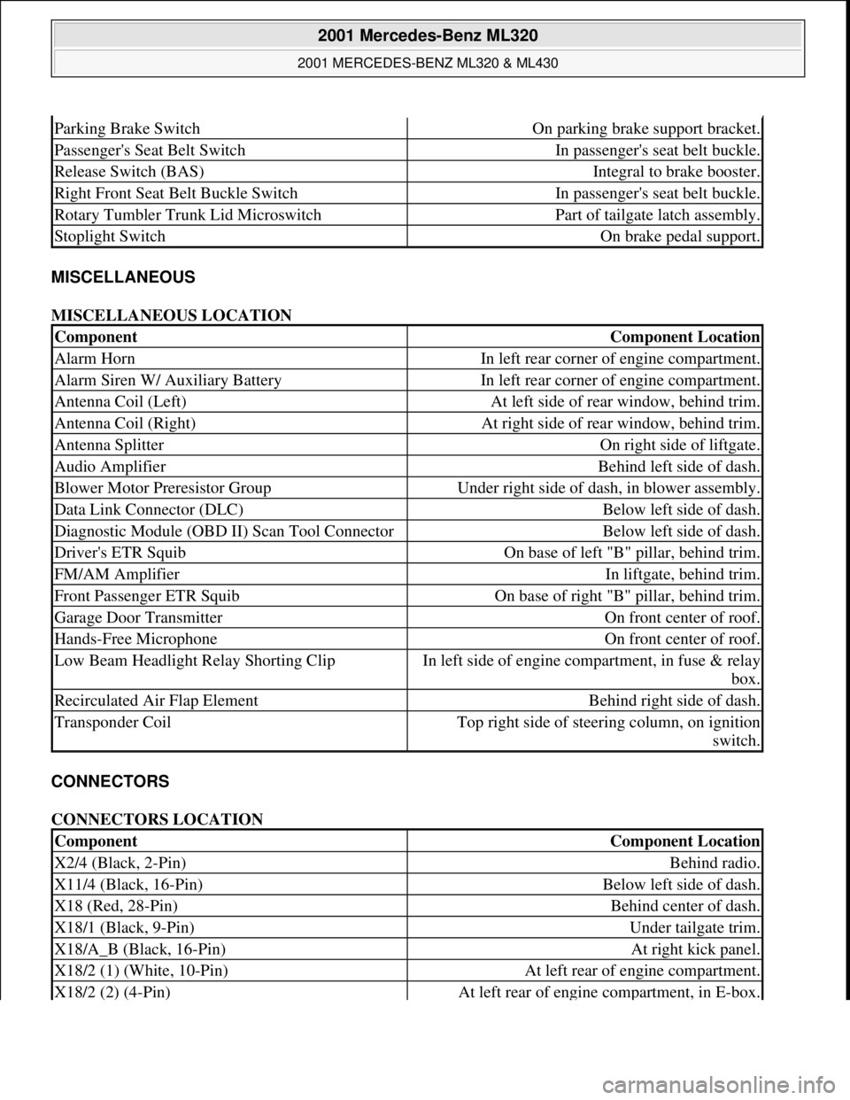
MISCELLANEOUS
MISCELLANEOUS LOCATION
CONNECTORS
CONNECTORS LOCATION
Parking Brake SwitchOn parking brake support bracket.
Passenger's Seat Belt SwitchIn passenger's seat belt buckle.
Release Switch (BAS)Integral to brake booster.
Right Front Seat Belt Buckle SwitchIn passenger's seat belt buckle.
Rotary Tumbler Trunk Lid MicroswitchPart of tailgate latch assembly.
Stoplight SwitchOn brake pedal support.
ComponentComponent Location
Alarm HornIn left rear corner of engine compartment.
Alarm Siren W/ Auxiliary BatteryIn left rear corner of engine compartment.
Antenna Coil (Left)At left side of rear window, behind trim.
Antenna Coil (Right)At right side of rear window, behind trim.
Antenna SplitterOn right side of liftgate.
Audio AmplifierBehind left side of dash.
Blower Motor Preresistor GroupUnder right side of dash, in blower assembly.
Data Link Connector (DLC)Below left side of dash.
Diagnostic Module (OBD II) Scan Tool ConnectorBelow left side of dash.
Driver's ETR SquibOn base of left "B" pillar, behind trim.
FM/AM AmplifierIn liftgate, behind trim.
Front Passenger ETR SquibOn base of right "B" pillar, behind trim.
Garage Door TransmitterOn front center of roof.
Hands-Free MicrophoneOn front center of roof.
Low Beam Headlight Relay Shorting ClipIn left side of engine compartment, in fuse & relay
box.
Recirculated Air Flap ElementBehind right side of dash.
Transponder CoilTop right side of steering column, on ignition
switch.
ComponentComponent Location
X2/4 (Black, 2-Pin)Behind radio.
X11/4 (Black, 16-Pin)Below left side of dash.
X18 (Red, 28-Pin)Behind center of dash.
X18/1 (Black, 9-Pin)Under tailgate trim.
X18/A_B (Black, 16-Pin)At right kick panel.
X18/2 (1) (White, 10-Pin)At left rear of engine compartment.
X18/2 (2) (4-Pin)At left rear of engine compartment, in E-box.
2001 Mercedes-Benz ML320
2001 MERCEDES-BENZ ML320 & ML430
me
Saturday, October 02, 2010 3:21:17 PMPage 6 © 2006 Mitchell Repair Information Company, LLC.
Page 2149 of 4133
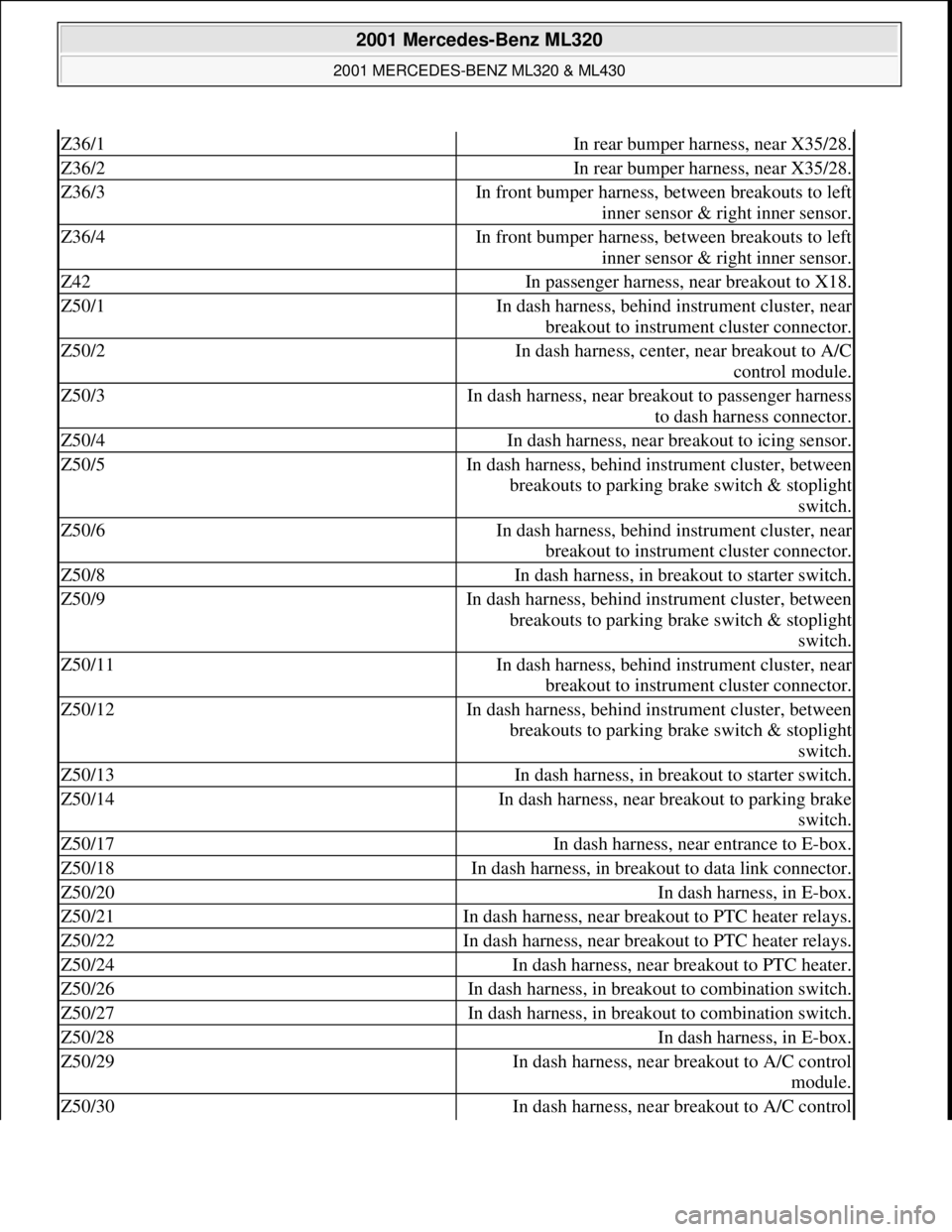
Z36/1In rear bumper harness, near X35/28.
Z36/2In rear bumper harness, near X35/28.
Z36/3In front bumper harness, between breakouts to left
inner sensor & right inner sensor.
Z36/4In front bumper harness, between breakouts to left
inner sensor & right inner sensor.
Z42In passenger harness, near breakout to X18.
Z50/1In dash harness, behind instrument cluster, near
breakout to instrument cluster connector.
Z50/2In dash harness, center, near breakout to A/C
control module.
Z50/3In dash harness, near breakout to passenger harness
to dash harness connector.
Z50/4In dash harness, near breakout to icing sensor.
Z50/5In dash harness, behind instrument cluster, between
breakouts to parking brake switch & stoplight
switch.
Z50/6In dash harness, behind instrument cluster, near
breakout to instrument cluster connector.
Z50/8In dash harness, in breakout to starter switch.
Z50/9In dash harness, behind instrument cluster, between
breakouts to parking brake switch & stoplight
switch.
Z50/11In dash harness, behind instrument cluster, near
breakout to instrument cluster connector.
Z50/12In dash harness, behind instrument cluster, between
breakouts to parking brake switch & stoplight
switch.
Z50/13In dash harness, in breakout to starter switch.
Z50/14In dash harness, near breakout to parking brake
switch.
Z50/17In dash harness, near entrance to E-box.
Z50/18In dash harness, in breakout to data link connector.
Z50/20In dash harness, in E-box.
Z50/21In dash harness, near breakout to PTC heater relays.
Z50/22In dash harness, near breakout to PTC heater relays.
Z50/24In dash harness, near breakout to PTC heater.
Z50/26In dash harness, in breakout to combination switch.
Z50/27In dash harness, in breakout to combination switch.
Z50/28In dash harness, in E-box.
Z50/29In dash harness, near breakout to A/C control
module.
Z50/30In dash harness, near breakout to A/C control
2001 Mercedes-Benz ML320
2001 MERCEDES-BENZ ML320 & ML430
me
Saturday, October 02, 2010 3:21:17 PMPage 9 © 2006 Mitchell Repair Information Company, LLC.
Page 2183 of 4133
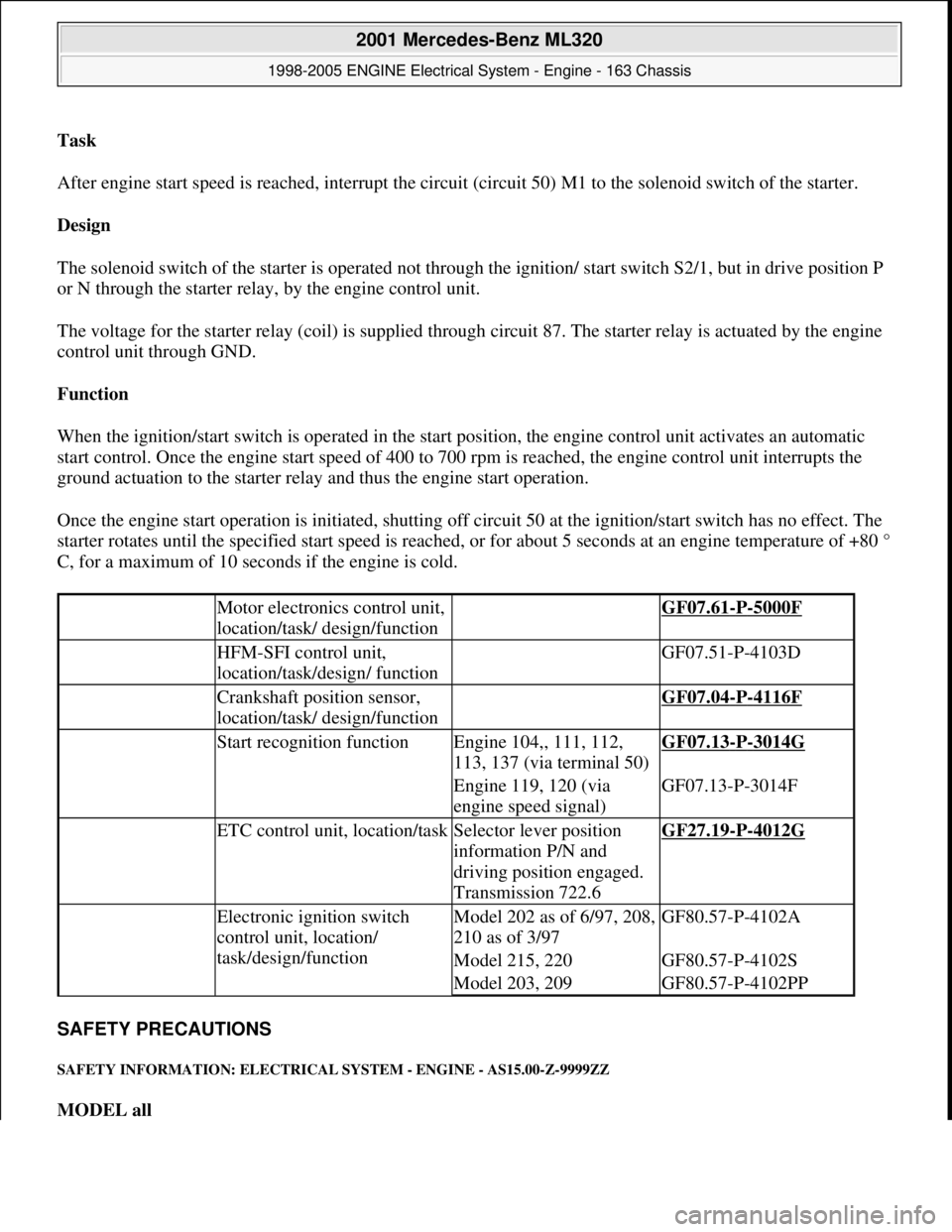
Task
After engine start speed is reached, interrupt the circuit (circuit 50) M1 to the solenoid switch of the starter.
Design
The solenoid switch of the starter is operated not through the ignition/ start switch S2/1, but in drive position P
or N through the starter relay, by the engine control unit.
The voltage for the starter relay (coil) is supplied through circuit 87. The starter relay is actuated by the engine
control unit through GND.
Function
When the ignition/start switch is operated in the start position, the engine control unit activates an automatic
start control. Once the engine start speed of 400 to 700 rpm is reached, the engine control unit interrupts the
ground actuation to the starter relay and thus the engine start operation.
Once the engine start operation is initiated, shutting off circuit 50 at the ignition/start switch has no effect. The
starter rotates until the specified start speed is reached, or for about 5 seconds at an engine temperature of +80 °
C, for a maximum of 10 seconds if the engine is cold.
SAFETY PRECAUTIONS
SAFETY INFORMATION: ELECTRICAL SYSTEM - ENGINE - AS15.00-Z-9999ZZ
MODEL all
Motor electronics control unit,
location/task/ design/function GF07.61-P-5000F
HFM-SFI control unit,
location/task/design/ function GF07.51-P-4103D
Crankshaft position sensor,
location/task/ design/function GF07.04-P-4116F
Start recognition functionEngine 104,, 111, 112,
113, 137 (via terminal 50)GF07.13-P-3014G
Engine 119, 120 (via
engine speed signal)GF07.13-P-3014F
ETC control unit, location/taskSelector lever position
information P/N and
driving position engaged.
Transmission 722.6GF27.19-P-4012G
Electronic ignition switch
control unit, location/
task/design/functionModel 202 as of 6/97, 208,
210 as of 3/97GF80.57-P-4102A
Model 215, 220GF80.57-P-4102S
Model 203, 209GF80.57-P-4102PP
2001 Mercedes-Benz ML320
1998-2005 ENGINE Electrical System - Engine - 163 Chassis
me
Saturday, October 02, 2010 3:18:54 PMPage 29 © 2006 Mitchell Repair Information Company, LLC.
Page 2193 of 4133
version FB6 with code ZS6, -
special protection version FB7
with code ZS7, additional battery
100 Ah incl. cutoff relay code E26.
Model 463.248 with: special
protection version, code 979, -
special protection version FB6,
code ZS6, -special protection
version FB7, code ZS7, -additional
battery 100 Ah including cutoff
relay, code E26.AR54.10-P-0003PM
3.1Unclip cover on front
side of engineModel 211, 215, 220, 230.475/476
4.1Remove engine cover
with integrated air filterExcept model 170.466,
203.065/076/265/276, 209.376/476
from 24.4.04, 211.076/276,
215.374, 220.074/174, 230.474,
463.270/271
The air filter is integrated in the
engine cover. Remove the engine
cover or the air filter housing by
pulling it from the cylinder head
covers vertically in the upward
direction.
4.2Remove air filter housingModel 170.466, 203.065/265,
211.076/276, 215.374,
220.074/174, 230.474AR09.10-P-1150SVK
Model 203.076 /276, 209.376 /476
from 24.4.04, 171.473AR09.10-P-1150AC
Model 463.270/271AR09.10-P-1150GX
5Unscrew screw (5/3) *BA15.10-P-1001-
04A
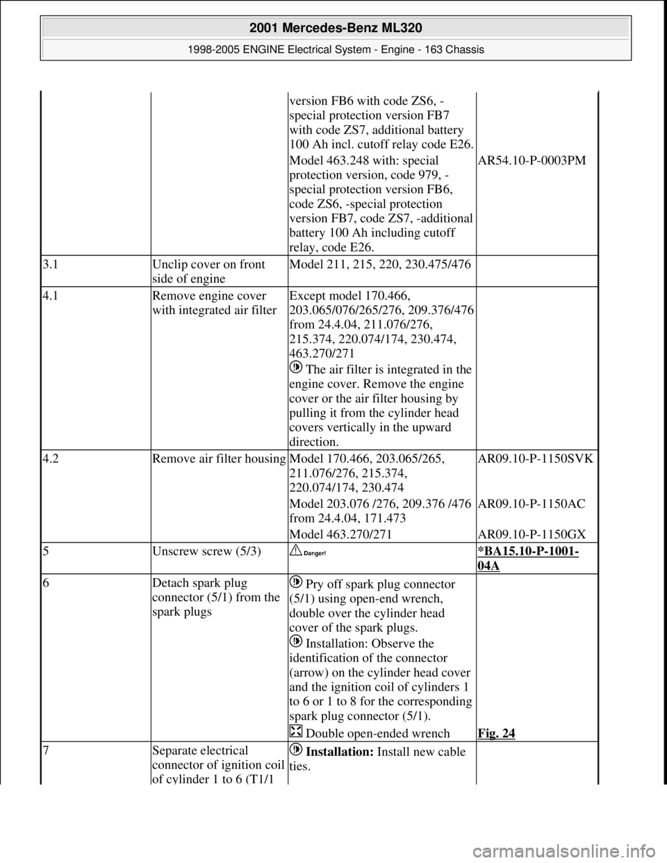
6Detach spark plug
connector (5/1) from the
spark plugs Pry off spark plug connector
(5/1) using open-end wrench,
double over the cylinder head
cover of the spark plugs.
Installation: Observe the
identification of the connector
(arrow) on the cylinder head cover
and the ignition coil of cylinders 1
to 6 or 1 to 8 for the corresponding
spark plug connector (5/1).
Double open-ended wrenchFig. 24
7Separate electrical
connector of ignition coil
of cylinder 1 to 6 (T1/1 Installation: Install new cable
ties.
2001 Mercedes-Benz ML320
1998-2005 ENGINE Electrical System - Engine - 163 Chassis
me
Saturday, October 02, 2010 3:18:54 PMPage 39 © 2006 Mitchell Repair Information Company, LLC.