Page 1692 of 4133
Fig. 107: Wiper System Test Of Electrical System Wiper Motor
WIPER SYSTEM TEST OF ELE CTRICAL SYSTEM TAILGATE WIPER RELAY - AD82.30-P-6002-03GH
Fig. 108: Wiper System Test Of Elec trical System Tailgate Wiper Relay
WIPER SYSTEM TEST OF ELECTRICAL SYSTEM WASHER PUMP - AD82.30-P-6002-04GH
2001 Mercedes-Benz ML320
1998-2005 ACCESSORIES & BODY, CAB Electr ical System - Body - 163 Chassis
me
Saturday, October 02, 2010 3:30:07 PMPage 197 © 2006 Mitchell Repair Information Company, LLC.
Page 1696 of 4133

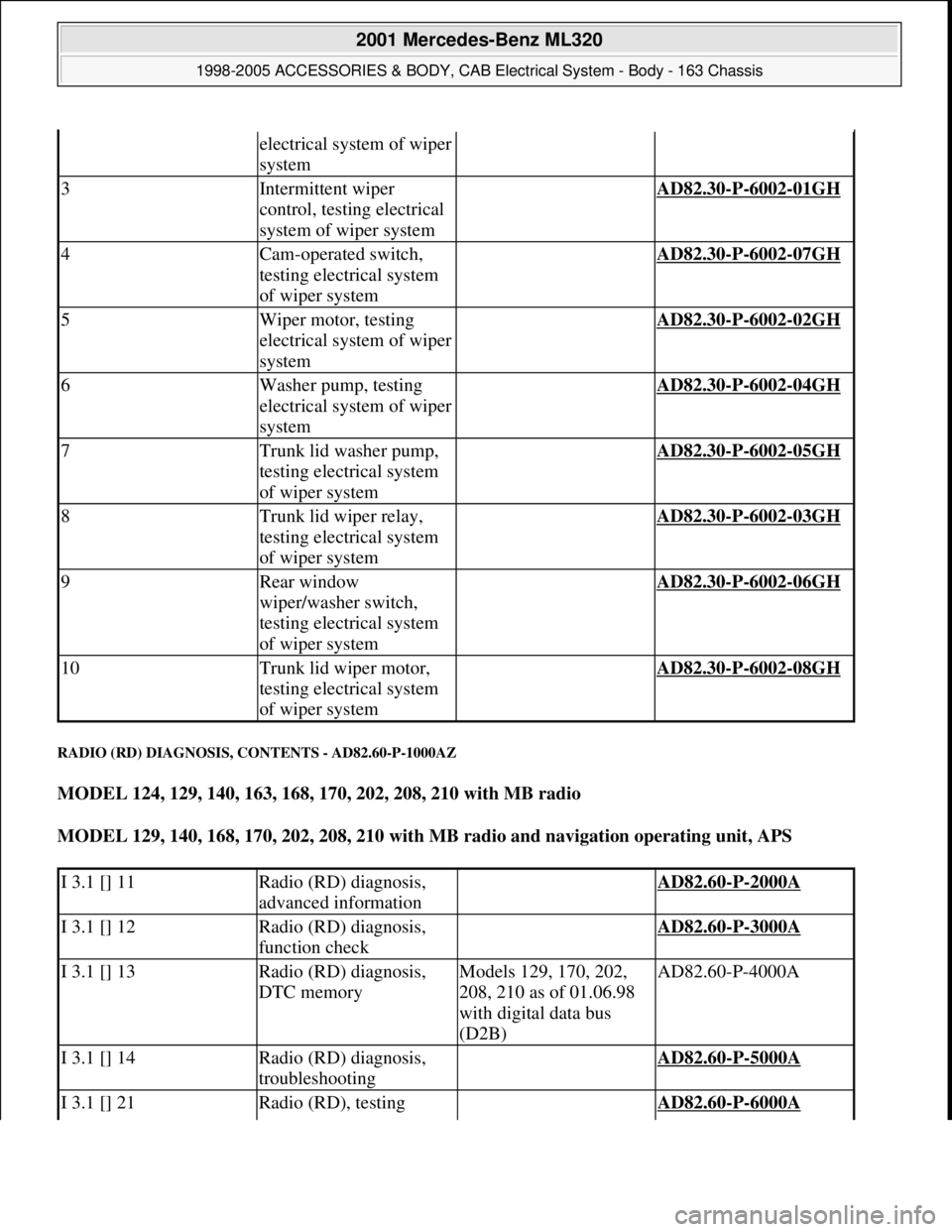
RADIO (RD) DIAGNOSIS, CONTENTS - AD82.60-P-1000AZ
MODEL 124, 129, 140, 163, 168, 170, 202, 208, 210 with MB radio
MODEL 129, 140, 168, 170, 202, 208, 210 with MB radio and navigation operating unit, APS
electrical system of wiper
system
3Intermittent wiper
control, testing electrical
system of wiper system AD82.30-P-6002-01GH
4Cam-operated switch,
testing electrical system
of wiper system AD82.30-P-6002-07GH
5Wiper motor, testing
electrical system of wiper
system AD82.30-P-6002-02GH
6Washer pump, testing
electrical system of wiper
system AD82.30-P-6002-04GH
7Trunk lid washer pump,
testing electrical system
of wiper system AD82.30-P-6002-05GH
8Trunk lid wiper relay,
testing electrical system
of wiper system AD82.30-P-6002-03GH
9Rear window
wiper/washer switch,
testing electrical system
of wiper system AD82.30-P-6002-06GH
10Trunk lid wiper motor,
testing electrical system
of wiper system AD82.30-P-6002-08GH
I 3.1 [] 11Radio (RD) diagnosis,
advanced information AD82.60-P-2000A
I 3.1 [] 12Radio (RD) diagnosis,
function check AD82.60-P-3000A
I 3.1 [] 13Radio (RD) diagnosis,
DTC memoryModels 129, 170, 202,
208, 210 as of 01.06.98
with digital data bus
(D2B)AD82.60-P-4000A
I 3.1 [] 14Radio (RD) diagnosis,
troubleshooting AD82.60-P-5000A
I 3.1 [] 21Radio (RD), testing AD82.60-P-6000A
2001 Mercedes-Benz ML320
1998-2005 ACCESSORIES & BODY, CAB Electrical System - Body - 163 Chassis
me
Saturday, October 02, 2010 3:30:07 PMPage 201 © 2006 Mitchell Repair Information Company, LLC.
Page 1780 of 4133
Fig. 188: Identifying Air Conditioning System Hose And Clip
Remove/Install
1Remove upper frame cross
member AR62.30-P-2300GH
2Drain the washer fluid
reservoir Manual pumpFig. 189
3Disconnect connectors
and hoses from pumps (5)Loosen wiring harness
from the side of the
washer fluid reservoir. If
fitted, disconnect plug
from washer fluid level
indicator switch.
4Unscrew bolt (2)
5Loosen air conditioning
hose (3) from clip (4)
6.1Remove covers and
locking clips from fuse
and relay module Only Model 163.128.
7Detach cooling module
(10) from lower grommets
8Remove washer fluid
reservoir (1) Loosen washer fluid
reservoir (1)from lower
grommets (6). Lift up
2001 Mercedes-Benz ML320
1998-2005 ACCESSORIES & BODY, CAB Electrical System - Body - 163 Chassis
me
Saturday, October 02, 2010 3:30:09 PMPage 285 © 2006 Mitchell Repair Information Company, LLC.
Page 1814 of 4133
![MERCEDES-BENZ ML430 1997 Complete Repair Manual Front seats
REPLACE FIBER OPTICAL CABLE (D2B) BETWEEN THE RADIO AND E-CALL CONTROL MODULE/CTEL [TEL]
INTERFACE (AFTER TESTING) - AR82.95-P-0015GH
MODEL 163.136 #A as of 051500, 163.136 #X as of 70 MERCEDES-BENZ ML430 1997 Complete Repair Manual Front seats
REPLACE FIBER OPTICAL CABLE (D2B) BETWEEN THE RADIO AND E-CALL CONTROL MODULE/CTEL [TEL]
INTERFACE (AFTER TESTING) - AR82.95-P-0015GH
MODEL 163.136 #A as of 051500, 163.136 #X as of 70](/manual-img/4/57307/w960_57307-1813.png)
Front seats
REPLACE FIBER OPTICAL CABLE (D2B) BETWEEN THE RADIO AND E-CALL CONTROL MODULE/CTEL [TEL]
INTERFACE (AFTER TESTING) - AR82.95-P-0015GH
MODEL 163.136 #A as of 051500, 163.136 #X as of 708319, 163.154 #A as of 051500, 163.154 #X as of
708319, 163.172 #A as of 051500, 163.172 #X as of 708319, 163.113/128/157/174/175 with CODE (852)
CTEL preinstallation assembly at dome with CODE (854) MB portable cellular telephone
MODEL 163.154 /172 /174 #A as of 221506, 163.157/175 with CODE (349) E Call emergency call system
with CODE (494a) USA version
1Remove fuse f8 from fuse
and relay module
2Unscrew screws on front
seat console *BA91.10-P-1001-01B
3Angle front seat back
until it rests against the
rear bench seat and fasten
with outer seat belt Remove wiring
harness for E-call speaker
from E-call bracket.
Cover the floor covering
behind the front seat to
avoid contamination.
4Detach connector (2) and
antenna plug (4) from the
E-call control module
(A35/8)
5Detach conductive
coupling D2B (3) Do not kink or stretch
fiber optic cable. Press
protective caps on
conductive coupling and
device connection.AR82.95-P-0005-01A
6Unscrew screws (5)
7Remove E-call control
module (A35/8)
8Install in the reverse order
NumberDesignationModel Series 163
BA91.10-P-1001-01BBolt of seating mounting
bracket to vehicle floorNm40
2001 Mercedes-Benz ML320
1998-2005 ACCESSORIES & BODY, CAB Electrical System - Body - 163 Chassis
me
Saturday, October 02, 2010 3:30:10 PMPage 319 © 2006 Mitchell Repair Information Company, LLC.
Page 1836 of 4133
Fig. 245: Identifying Fiber Optic Cable Connector (X39/43) (B) And Fiber Optic Cable Wiring
Harness
CONNECT WIRING HARNESS - AZ82.20-P-0001-02B
Model 163.113/128/136/154/172/174/175
Do not touch parts which conduct high voltages. Persons who wear electronic implants (e.g. heart
pacemakers) must not carry out any work on such components.
Connection diagram of wiring harness of illuminated door sill molding
Fig. 246: Connection Diagram Of Wiring Harness Of Illuminated Door Sill Molding
1. Raise fuse block in fuse and relay module (F1).
2. Push to the side the foam rubber block for cable openin
g into interior.
2001 Mercedes-Benz ML320
1998-2005 ACCESSORIES & BODY, CAB Electrical System - Body - 163 Chassis
me
Saturday, October 02, 2010 3:30:11 PMPage 341 © 2006 Mitchell Repair Information Company, LLC.
Page 1837 of 4133

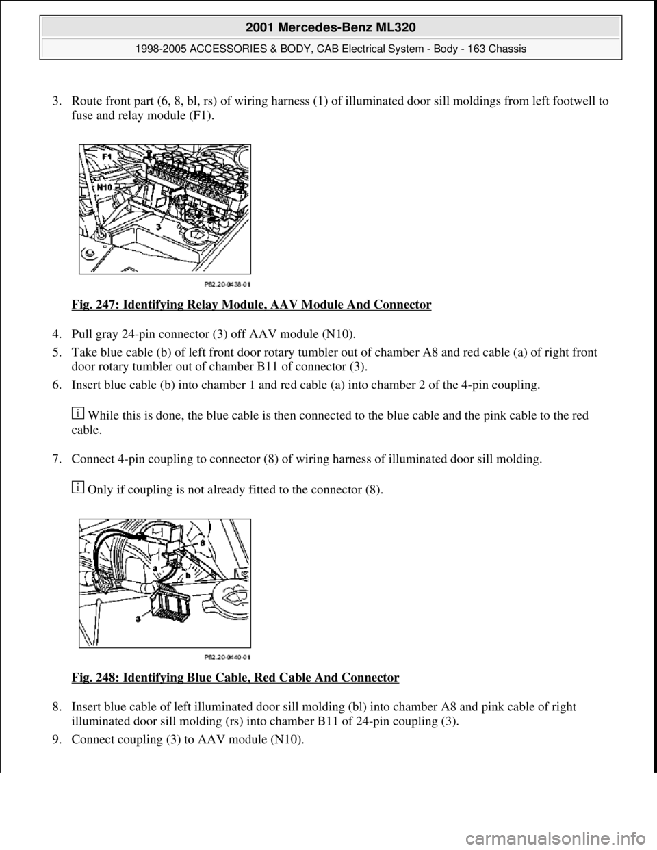
3. Route front part (6, 8, bl, rs) of wiring harness (1) of illuminated door sill moldings from left footwell to
fuse and relay module (F1).
Fig. 247: Identifying Relay Module, AAV Module And Connector
4. Pull gray 24-pin connector (3) off AAV module (N10).
5. Take blue cable (b) of left front door rotary tumbler out of chamber A8 and red cable (a) of right front
door rotary tumbler out of chamber B11 of connector (3).
6. Insert blue cable (b) into chamber 1 and red cable (a) into chamber 2 of the 4-pin coupling.
While this is done, the blue cable is then connected to the blue cable and the pink cable to the red
cable.
7. Connect 4-pin coupling to connector (8) of wiring harness of illuminated door sill molding.
Only if coupling is not already fitted to the connector (8).
Fig. 248: Identifying Blue Cable, Red Cable And Connector
8. Insert blue cable of left illuminated door sill molding (bl) into chamber A8 and pink cable of right
illuminated door sill molding (rs) into chamber B11 of 24-pin coupling (3).
9. Connect couplin
g (3) to AAV module (N10).
2001 Mercedes-Benz ML320
1998-2005 ACCESSORIES & BODY, CAB Electrical System - Body - 163 Chassis
me
Saturday, October 02, 2010 3:30:11 PMPage 342 © 2006 Mitchell Repair Information Company, LLC.
Page 1838 of 4133

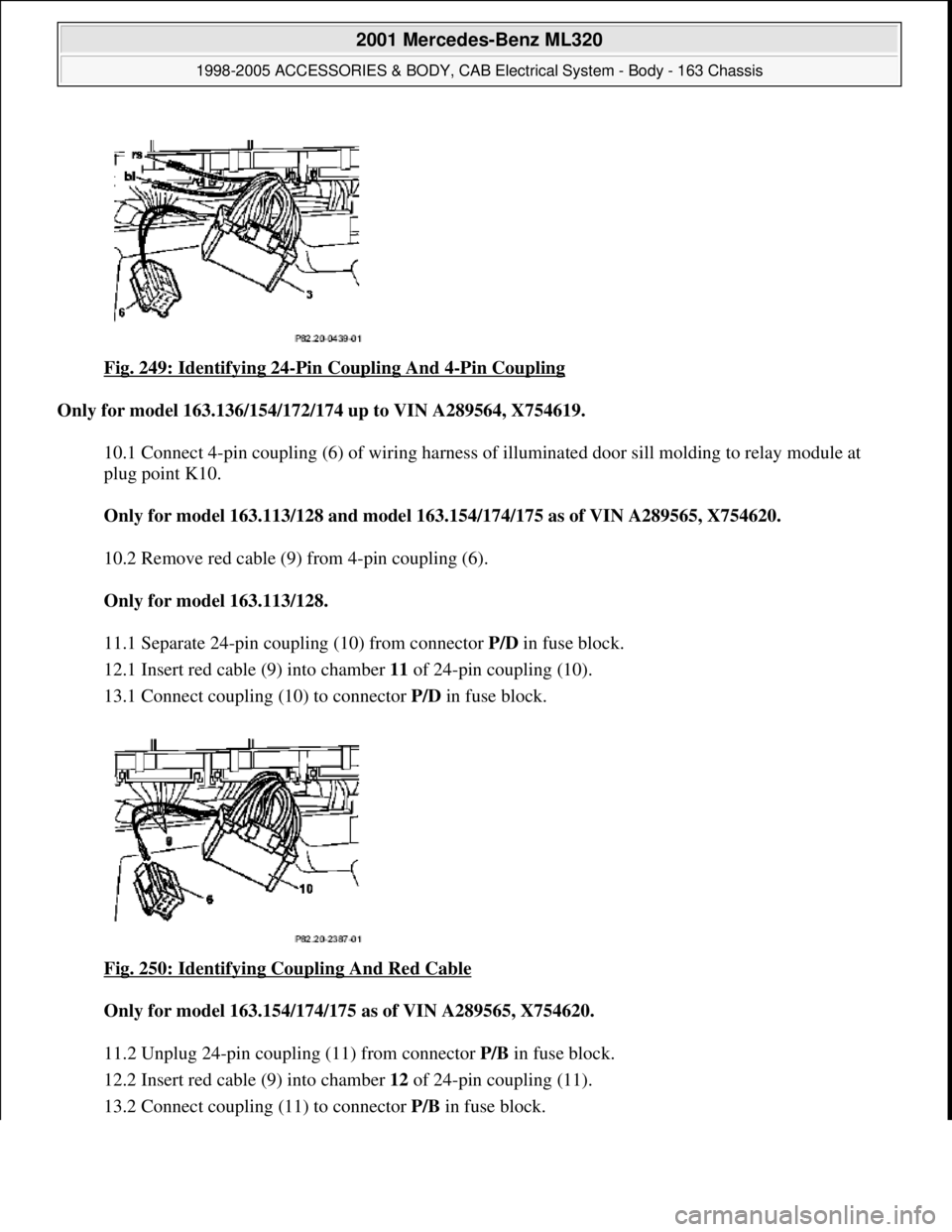
Fig. 249: Identifying 24-Pin Coupling And 4-Pin Coupling
Only for model 163.136/154/172/174 up to VIN A289564, X754619.
10.1 Connect 4-pin coupling (6) of wiring harness of illuminated door sill molding to relay module at
plug point K10.
Only for model 163.113/128 and mode l 163.154/174/175 as of VIN A289565, X754620.
10.2 Remove red cable (9) from 4-pin coupling (6).
Only for model 163.113/128.
11.1 Separate 24-pin coupli ng (10) from connector P/D in fuse block.
12.1 Insert red cable (9) into chamber 11 of 24-pin coupling (10).
13.1 Connect coupling (10) to connector P/D in fuse block.
Fig. 250: Identifying Coupling And Red Cable
Only for model 163.154/174/ 175 as of VIN A289565, X754620.
11.2 Unplug 24-pin coupling (11) from connector P/B in fuse block.
12.2 Insert red cable (9) into chamber 12 of 24-pin coupling (11).
13.2 Connect couplin
g (11) to connector P/Bin fuse block.
2001 Mercedes-Benz ML320
1998-2005 ACCESSORIES & BODY, CAB Electr ical System - Body - 163 Chassis
me
Saturday, October 02, 2010 3:30:11 PMPage 343 © 2006 Mitchell Repair Information Company, LLC.
Page 1839 of 4133
Only if fuse is not already present.
14 Insert enclosed 15 A fu se into plug position F40.
15 Fix wiring harness of illuminated door sill molding in fuse and relay module (F1).
16 Attach fuse block.
2 bolts.
17 Insert foam rubber block into rear of fuse and relay module.
Fig. 251: Identifying 24
-Pin Coupling And 4-Pin Coupling
Fig. 252: Identifying 2
-Pin Coupling And Harness Inverter
2001 Mercedes-Benz ML320
1998-2005 ACCESSORIES & BODY, CAB Electr ical System - Body - 163 Chassis
me
Saturday, October 02, 2010 3:30:11 PMPage 344 © 2006 Mitchell Repair Information Company, LLC.