1997 MERCEDES-BENZ ML430 battery replacement
[x] Cancel search: battery replacementPage 16 of 4133
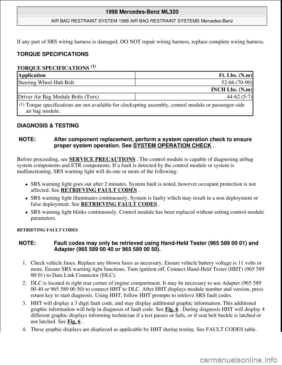
If any part of SRS wiring harness is damaged, DO NOT repair wiring harness, replace complete wiring harness.
TORQUE SPECIFICATIONS
TORQUE SPECIFICATIONS
(1)
DIAGNOSIS & TESTING
Before proceeding, see SERVICE PRECAUTIONS
. The control module is capable of diagnosing airbag
system components and ETR components. If a fault is detected by the control module or system is
malfunctioning, SRS warning light will do one or more of the following:
SRS warning light goes out after 2 minutes. System fault is noted, however occupant protection is not
affected. See RETRIEVING FAULT CODES
.
SRS warning light illuminates continuously. System is faulty which may result in a non deployment or
false deployment. See RETRIEVING FAULT CODES
.
SRS warning light blinks continuously. Control module has been replaced without setting control module
parameters.
RETRIEVING FAULT CODES
1. Check vehicle fuses. Replace any blown fuses as necessary. Ensure vehicle battery voltage is 11 volts or
more. Ensure SRS warning light functions. Turn ignition off. Connect Hand-Held Tester (HHT) (965 589
00 01) to Data Link Connector (DLC).
2. DLC is located in right rear corner of engine compartment. It may be necessary to use Adapter (965 589
00 40 or 965 589 00 50) to connect HHT to DLC. After HHT displays module number and version, press
return key to start diagnosis. Using HHT, follow HHT prompts to retrieve SRS fault codes.
3. HHT will display a 3 digit fault code, and may display additional graphic information. This additional
graphic information will help in diagnosis of fault code. See Fig. 6
. During diagnosis HHT will display 4
different graphic displays informing technician if a test passes or fails, or if seat belt buckle is latched or
not latched. See Fig. 6
.
4. These
graphic displays are displayed as applicable by HHT during testing. See FAULT CODES table.
ApplicationFt. Lbs. (N.m)
Steering Wheel Hub Bolt52-66 (70-90)
INCH Lbs. (N.m)
Driver Air Bag Module Bolts (Torx)44-62 (5-7)
(1)Torque specifications are not available for clockspring assembly, control module or passenger-side
air bag module.
NOTE: After component replacement, perform a system operation check to ensure
proper system operation. See SYSTEM OPERATION CHECK
.
NOTE: Fault codes may only be retrieved using Hand-Held Tester (965 589 00 01) and
Adapter (965 589 00 40 or 965 589 00 50).
1998 Mercedes-Benz ML320
AIR BAG RESTRAINT SYSTEM 1998 AIR BAG RESTRAINT SYSTEMS Mercedes-Benz
me
Saturday, October 02, 2010 3:33:14 PMPage 16 © 2006 Mitchell Repair Information Company, LLC.
Page 54 of 4133

4 Contents
Practical hintsFirst aid kit .....................................228
Fuses ................................................228
Electrical outlet ..............................230
Stowing things in the vehicle ......230
Hood ................................................. 231
Checking engine oil level .............233
Automatic transmission
fluid level ...................................234
Engine oil consumption ................234
Coolant level ...................................234
Adding coolant ...........................235
Windshield washer/headlamp
cleaning system .........................236
Windshield and
headlamp washer fluid
mixing ratio ................................237Vehicle jack, wheel bolt
wrench and screwdriver ......... 237
Air pump ......................................... 239
Wheels ............................................ 240
Tire replacement ....................... 240
Rotating wheels ......................... 241
Spare wheel .................................... 242
Changing wheels ........................... 245
Tire inflation pressure ................. 250
Battery ............................................. 251
Jump starting ................................. 253
Towing the vehicle ........................ 255
Transmission selector lever,
manually unlocking .................. 259
Stranded vehicle ............................ 259Exterior lamps ................................260
Headlamp assembly ................... 261
Taillamp assemblies ..................265
Adjusting headlamp aim ...............268
Remote control
battery replacement .................270
Synchronizing
remote control ............................ 271
Emergency operation of
sliding/pop-up roof ...................272
Emergency operation of
Skyview Top ...............................273
Manual release for
fuel filler flap ............................. 274
Replacing wiper blades .................275
Roof rack ......................................... 276
Page 277 of 4133
227 Contents - Practical hints
Te ch n ica l
data Instruments
and controlsOperation DrivingInstrument
cluster displayPractical hintsCar care Index
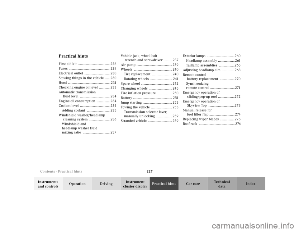
Practical hintsFirst aid kit .....................................228
Fuses ................................................228
Electrical outlet ..............................230
Stowing things in the vehicle ......230
Hood ................................................. 231
Checking engine oil level .............233
Automatic transmission
fluid level ...................................234
Engine oil consumption ................234
Coolant level ...................................234
Adding coolant ...........................235
Windshield washer/headlamp
cleaning system .........................236
Windshield and
headlamp washer fluid
mixing ratio ................................237Vehicle jack, wheel bolt
wrench and screwdriver ......... 237
Air pump ......................................... 239
Wheels ............................................ 240
Tire replacement ....................... 240
Rotating wheels ......................... 241
Spare wheel .................................... 242
Changing wheels ........................... 245
Tire inflation pressure ................. 250
Battery ............................................. 251
Jump starting ................................. 253
Towing the vehicle ........................ 255
Transmission selector lever,
manually unlocking .................. 259
Stranded vehicle ............................ 259Exterior lamps ................................260
Headlamp assembly ................... 261
Taillamp assemblies ..................265
Adjusting headlamp aim ...............268
Remote control
battery replacement .................270
Synchronizing
remote control ............................ 271
Emergency operation of
sliding/pop-up roof ...................272
Emergency operation of
Skyview Top ...............................273
Manual release for
fuel filler flap ............................. 274
Replacing wiper blades .................275
Roof rack ......................................... 276
Page 301 of 4133
251 Battery
Te ch n ica l
data Instruments
and controlsOperation DrivingInstrument
cluster displayPractical hintsCar care Index If a tire constantly loses air, it should be inspected for
damage.
The spare tire should be checked periodically for
condition and inflation. Spare tire will age and become
worn over time even if never used, and thus should be
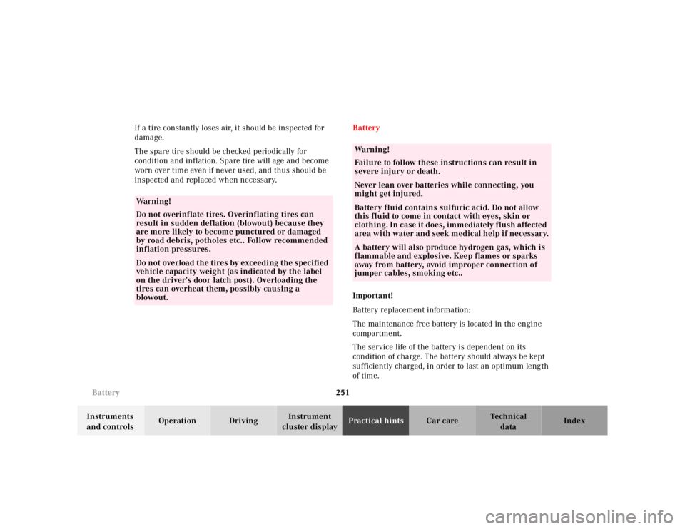
inspected and replaced when necessary.Battery
Important!
Battery replacement information:
The maintenance-free battery is located in the engine
compartment.
The service life of the battery is dependent on its
condition of charge. The battery should always be kept
sufficiently charged, in order to last an optimum length
of time.
Wa r n i n g !
Do not overinflate tires. Overinflating tires can
result in sudden deflation (blowout) because they
are more likely to become punctured or damaged
by road debris, potholes etc.. Follow recommended
inflation pressures.Do not overload the tires by exceeding the specified
vehicle capacity weight (as indicated by the label
on the driver’s door latch post). Overloading the
tires can overheat them, possibly causing a
blowout.
Wa r n i n g !
Failure to follow these instructions can result in
severe injury or death.Never lean over batteries while connecting, you
might get injured.Battery fluid contains sulfuric acid. Do not allow
this fluid to come in contact with eyes, skin or
clothing. In case it does, immediately flush affected
area with water and seek medical help if necessary.A battery will also produce hydrogen gas, which is
flammable and explosive. Keep flames or sparks
away from battery, avoid improper connection of
jumper cables, smoking etc..
Page 320 of 4133
270 Remote control
Te ch n ica l
data Instruments
and controlsOperation DrivingInstrument
cluster displayPractical hintsCar care Index
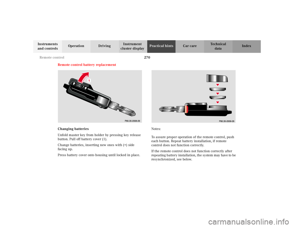
Remote control battery replacement
Changing batteries
Unfold master key from holder by pressing key release
button. Pull off battery cover (1).
Change batteries, inserting new ones with (+) side
facing up.
Press battery cover onto housing until locked in place.Notes:
To assure proper operation of the remote control, push
each button. Repeat battery installation, if remote
control does not function correctly.
If the remote control does not function correctly after
repeating battery installation, the system may have to be
resynchronized, see below.
Page 321 of 4133
271 Remote control
Te ch n ica l
data Instruments
and controlsOperation DrivingInstrument
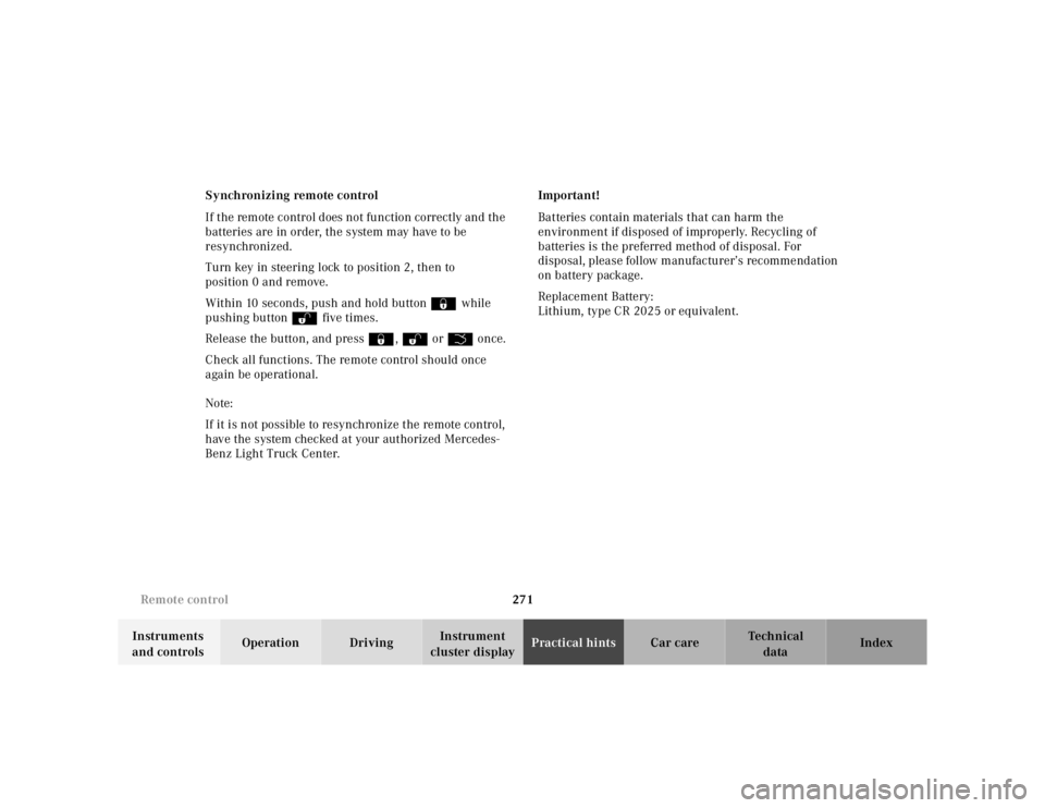
cluster displayPractical hintsCar care Index Synchronizing remote control
If the remote control does not function correctly and the
batteries are in order, the system may have to be
resynchronized.
Turn key in steering lock to position 2, then to
position 0 and remove.
Within 10 seconds, push and hold button‹ while
pushing buttonΠfive times.
Release the button, and press‹, Œ orŠ once.
Check all functions. The remote control should once
again be operational.
Note:
If it is not possible to resynchronize the remote control,
have the system checked at your authorized Mercedes-
Benz Light Truck Center.Important!
Batteries contain materials that can harm the
environment if disposed of improperly. Recycling of
batteries is the preferred method of disposal. For
disposal, please follow manufacturer’s recommendation
on battery package.
Replacement Battery:
Lithium, type CR 2025 or equivalent.
Page 358 of 4133
308 Index
Te ch n ica l
data Instruments
and controlsOperation DrivingInstrument
cluster displayPractical hints Car careIndex
Remote control ................................................................. 24
Battery replacement .................................................270
Changing batteries ...................................................270
Operation ..................................................................... 26
Synchronizing remote control ................................ 271
Removable cargo floor plates ....................................... 129
Replacement keys ............................................................ 25
Replacing bulbs ..............................................................260
Replacing wiper blade insert .......................................275
Reporting safety defects ................................................. 16
Reserve key ................................................................ 24, 25
Roadside assistance ......................................................... 10
Roadside assistance call
See Tele Aid ............................................................... 148
Roof rack ......................................................................... 276
SSafety guidelines for the seat belt, emergency
tensioning retractor and airbag ................................ 63
Screwdriver .....................................................................237
Seat belt warning lamp .................................................223
Seat belts ........................................................................... 46
Fastening ...................................................................... 48
Seat belt nonusage warning system ........................ 47Unfastening .................................................................. 50
Warning lamp ........................................................... 223
Seat belts and integrated restraint system .................. 46
Seat bench ....................................................................... 120
Seats, folding (Third row seats) ................................... 126
Seats, front ........................................................................37
Heated seats .................................................................44
Manual seats ................................................................39
Power seats .................................................................. 40
Service indicator
See Flexible service system (FSS) ............................ 87
Side marker lamp .......................................................... 264
Skyview Top ....................................................................109
Emergency operation .............................................. 273
Sliding/pop-up roof ........................................................107
Emergency operation .............................................. 272
Express opening ........................................................108
Synchronizing .......................................................... 272
Snow chains ....................................................................179
SOS-call
See Tele Aid ...............................................................148
Space-saver tire
Air pump ................................................................... 239
Spare parts service ....................................................... 284
Spare wheel ................................................................... 242
Space-saver tire ........................................................ 243
Page 367 of 4133
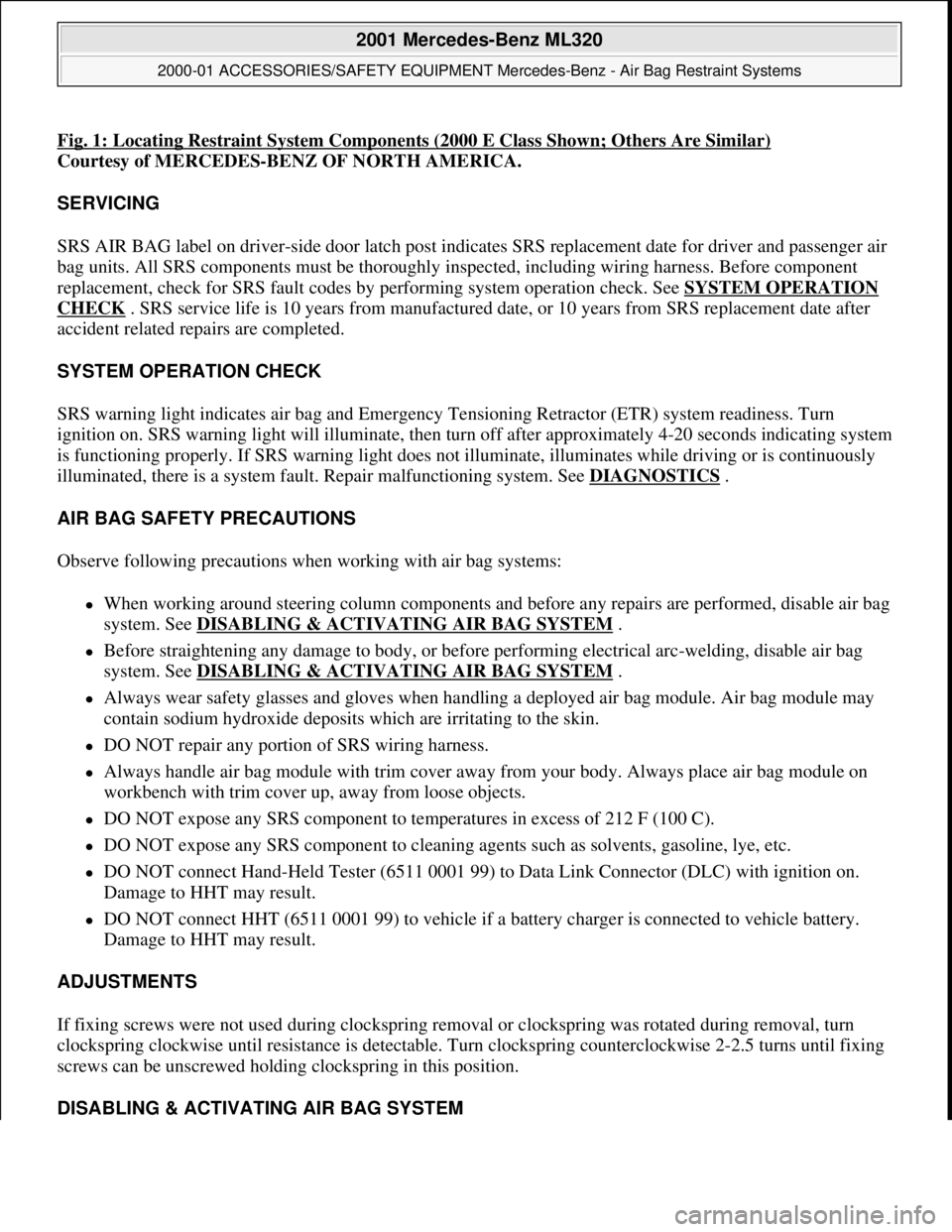
Fig. 1: Locating Restraint System Components (2000 E Class Shown; Others Are Similar)
Courtesy of MERCEDES-BENZ OF NORTH AMERICA.
SERVICING
SRS AIR BAG label on driver-side door latch post indicates SRS replacement date for driver and passenger air
bag units. All SRS components must be thoroughly insp ected, including wiring harness. Before component
replacement, check for SRS fault codes by performing system operation check. See SYSTEM OPERATION
CHECK . SRS service life is 10 years from manufactured date, or 10 years from SRS replacement date after
accident related repairs are completed.
SYSTEM OPERATION CHECK
SRS warning light indicates air ba g and Emergency Tensioning Retracto r (ETR) system readiness. Turn
ignition on. SRS warning light will illuminate, then turn off after approximately 4-20 seconds indicating system
is functioning properly. If SRS warning light does not illuminate, illuminates while driving or is continuously
illuminated, there is a system faul t. Repair malfunctioning system. See DIAGNOSTICS
.
AIR BAG SAFETY PRECAUTIONS
Observe following precautions when working with air bag systems:
When working around steering column components and be fore any repairs are performed, disable air bag
system. See DISABLING & ACTIVATING AIR BAG SYSTEM
.
Before straightening any damage to body, or before performing electrical arc-welding, disable air bag
system. See DISABLING & ACTIVATING AIR BAG SYSTEM
.
Always wear safety glasses and gloves when ha ndling a deployed air bag module. Air bag module may
contain sodium hydroxide deposits wh ich are irritating to the skin.
DO NOT repair any portion of SRS wiring harness.
Always handle air bag module with trim cover away from your body. Always place air bag module on
workbench with trim cover up, away from loose objects.
DO NOT expose any SRS component to temp eratures in excess of 212 F (100 C).
DO NOT expose any SRS component to cleaning agen ts such as solvents, gasoline, lye, etc.
DO NOT connect Hand-Held Tester (6511 0001 99) to Data Link Connector (DLC) with ignition on.
Damage to HHT may result.
DO NOT connect HHT (6511 0001 99) to vehicle if a battery charger is connected to vehicle battery.
Damage to HHT may result.
ADJUSTMENTS
If fixing screws were not used durin g clockspring removal or clockspring was rotated during removal, turn
clockspring clockwise until resistance is detectable. Turn clockspring counterclockwise 2-2.5 turns until fixing
screws can be unscrewed holdi ng clockspring in this position.
DISABLING & ACTIVATI NG AIR BAG SYSTEM
2001 Mercedes-Benz ML320
2000-01 ACCESSORIES/SAFETY EQUIPMENT Merc edes-Benz - Air Bag Restraint Systems
me
Saturday, October 02, 2010 3:44:45 PMPage 3 © 2006 Mitchell Repair Information Company, LLC.