1997 MERCEDES-BENZ ML430 battery
[x] Cancel search: batteryPage 4 of 4133

Several situations may arise requiring some form of disposal action, including:
Scrapping a vehicle containing a deployed air bag module and/or ETR.
Scrapping a vehicle with a live air bag module and/or ETR.
Disposal of a live but electrically faulty air bag module and/or ETR.
Disposal of a deployed air bag module and/or ETR.
DEPLOYED AIR BAG OR ETR
Deployed air bag module and/or ETR unit can be thrown away. None of its components are reusable. Deployed
air bag module is NOT classified as hazardous material.
SCRAPPED VEHICLE
1. Before proceeding, follow service precautions. See SERVICE PRECAUTIONS . Move vehicle
outdoors to a remote area, away from workshop and other personnel. Disconnect and shield negative
battery cable. Open all vehicle windows and doors.
2. Ensure air bag module is secured to steering wheel, and passenger air bag is secured to dash. Ensure ETR
seat belt assemblies are secured to "B" pillars and all seat belt buckles are latched. Remove loose objects
from front seat. DO NOT allow anyone inside vehicle.
3. Disable air bag system. See DISABLING & ACTIVATING AIR BAG SYSTEM
. Connect Trigger
Device (126-589-00-90-00) and Adapter Cable (126 589 21 63 00) to SRS system connector (X29/9)
located at passenger footwell area. See Fig. 5
. Move away from vehicle as far as trigger device wiring
will allow.
4. To deploy driver air bag and ETR, turn rotary knob on trigger device to position No. 1. Push battery
check pushbutton and ignition pushbutton simultaneously. Trigger light should illuminate indicating
driver air bag and ETR deployed. If trigger light is illuminated and driver air bag and/or ETR did not
deploy, driver air bag module and/or ETR is faulty. See UNDEPLOYED AIR BAG/ETR
.
5. To deploy passenger air bag detonator No. 1, turn rotary knob on trigger device to position No. 2. Push
battery check pushbutton and ignition pushbutton simultaneously. Trigger light should illuminate
indicating passenger air bag detonator No. 1 deployed. If trigger light is illuminated and passenger air bag
detonator No. 1 did not deploy, passenger air bag module is faulty. See UNDEPLOYED AIR
BAG/ETR .
6. To deploy passenger air bag detonator No. 2, turn rotary knob on trigger device to position No. 3. Push
battery check pushbutton and ignition pushbutton simultaneously. Trigger light should illuminate
indicating passenger air bag detonator No. 2 deployed. If trigger light is illuminated and passenger air bag
detonator No. 2 did not deploy, passenger air bag module is faulty. See UNDEPLOYED AIR
BAG/ETR . WARNING:An undeployed air bag module and/or ETR seat belt CANNOT be disposed
of without first being deployed. If this is not possible through procedures
outlined below, contact vehicle manufacturer for further instructions.
Perform remote deployment outdoors. Keep personnel at least 20 feet
away.
1998 Mercedes-Benz ML320
AIR BAG RESTRAINT SYSTEM 1998 AIR BAG RESTRAINT SYSTEMS Mercedes-Benz
me
Saturday, October 02, 2010 3:33:13 PMPage 4 © 2006 Mitchell Repair Information Company, LLC.
Page 14 of 4133
check to ensure system is functioning properly. See SYSTEM OPERATION CHECK .
Removal & Installation (SLK 230)
1. Before proceeding, see SERVICE PRECAUTIONS . Disable air bag system. See DISABLING &
ACTIVATING AIR BAG SYSTEM . Remove ignition key. Remove top section of instrument panel.
Fold vapor barrier toward front to reveal 2 screws. Disconnect passenger-side air bag module connector.
Remove 4 screws and passenger-side air bag module.
2. To install air bag module, reverse removal procedure. Activate air bag system. Perform system operation
check to ensure system is functioning properly. See SYSTEM OPERATION CHECK
.
SYSTEM OPERATION CHECK
SRS warning light indicates air bag and Emergency Tensioning Retractor (ETR) system readiness. Turn
ignition on. SRS warning light will light, and then go out after approximately 4 seconds indicating system is
functioning properly. If SRS warning light does not light, lights up while driving or lights all the time, there is a
system fault. Repair malfunctioning system. See DIAGNOSIS & TESTING
.
SERVICE PRECAUTIONS
Observe following precautions when working with air bag systems:
When working around steering column components and before any repairs are performed, disable air bag
system. See DISABLING & ACTIVATING AIR BAG SYSTEM
.
Before straightening any damage to body, or before performing electrical arc-welding, disable air bag
system. See DISABLING & ACTIVATING AIR BAG SYSTEM
.
Always wear safety glasses and gloves when handling a deployed air bag module. Air bag module may
contain sodium hydroxide deposits which are irritating to the skin.
DO NOT repair any portion of SRS wiring harness.
Always handle air bag module with trim cover away from your body. Always place air bag module on
workbench with trim cover up, away from loose objects.
DO NOT expose any SRS component to temperatures in excess of 212°F (100°C).
DO NOT expose any SRS component to cleaning agents such as solvents, gasoline, lye, etc.
DO NOT connect Hand-Held Tester (6511 0001 99) to Data Link Connector (DLC) with ignition on.
Damage to HHT may result.
DO NOT connect HHT (6511 0001 99) to vehicle if a battery charger is connected to vehicle battery.
Damage to HHT may result.
DISABLING & ACTIVATING AIR BAG SYSTEM DISABLING SYSTEM
Before proceeding, follow air bag service precautions. See SERVICE PRECAUTIONS
. Turn ignition off.
Disconnect and shield negative battery cable. Remove passenger foot mat. Remove passenger footrest.
Disconnect SRS system connector (X29/9) located at passenger footwell area. See Fig. 5
. System is now
disabled.
1998 Mercedes-Benz ML320
AIR BAG RESTRAINT SYSTEM 1998 AIR BAG RESTRAINT SYSTEMS Mercedes-Benz
me
Saturday, October 02, 2010 3:33:14 PMPage 14 © 2006 Mitchell Repair Information Company, LLC.
Page 16 of 4133
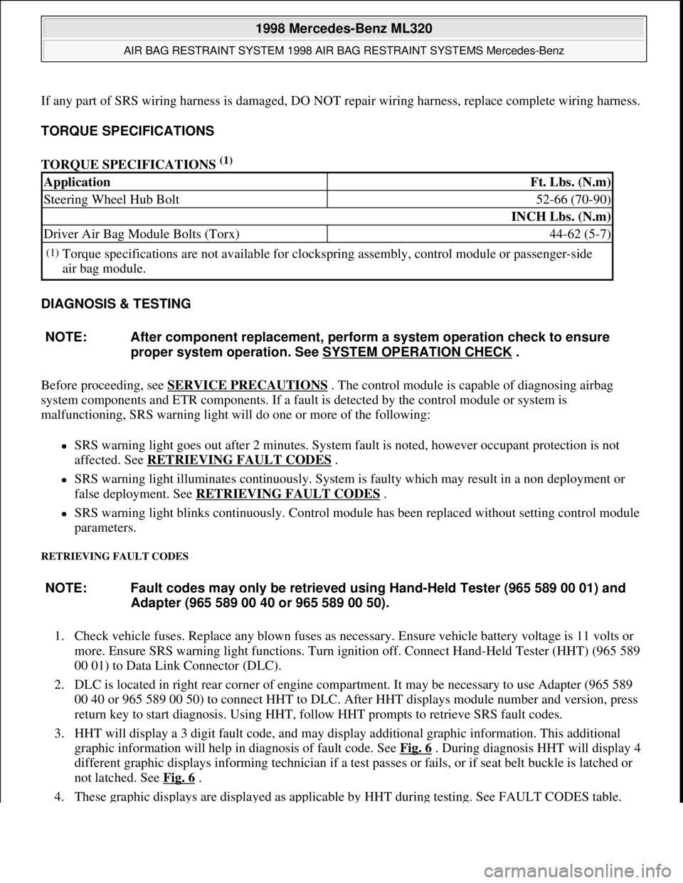
If any part of SRS wiring harness is damaged, DO NOT repair wiring harness, replace complete wiring harness.
TORQUE SPECIFICATIONS
TORQUE SPECIFICATIONS
(1)
DIAGNOSIS & TESTING
Before proceeding, see SERVICE PRECAUTIONS
. The control module is capable of diagnosing airbag
system components and ETR components. If a fault is detected by the control module or system is
malfunctioning, SRS warning light will do one or more of the following:
SRS warning light goes out after 2 minutes. System fault is noted, however occupant protection is not
affected. See RETRIEVING FAULT CODES
.
SRS warning light illuminates continuously. System is faulty which may result in a non deployment or
false deployment. See RETRIEVING FAULT CODES
.
SRS warning light blinks continuously. Control module has been replaced without setting control module
parameters.
RETRIEVING FAULT CODES
1. Check vehicle fuses. Replace any blown fuses as necessary. Ensure vehicle battery voltage is 11 volts or
more. Ensure SRS warning light functions. Turn ignition off. Connect Hand-Held Tester (HHT) (965 589
00 01) to Data Link Connector (DLC).
2. DLC is located in right rear corner of engine compartment. It may be necessary to use Adapter (965 589
00 40 or 965 589 00 50) to connect HHT to DLC. After HHT displays module number and version, press
return key to start diagnosis. Using HHT, follow HHT prompts to retrieve SRS fault codes.
3. HHT will display a 3 digit fault code, and may display additional graphic information. This additional
graphic information will help in diagnosis of fault code. See Fig. 6
. During diagnosis HHT will display 4
different graphic displays informing technician if a test passes or fails, or if seat belt buckle is latched or
not latched. See Fig. 6
.
4. These
graphic displays are displayed as applicable by HHT during testing. See FAULT CODES table.
ApplicationFt. Lbs. (N.m)
Steering Wheel Hub Bolt52-66 (70-90)
INCH Lbs. (N.m)
Driver Air Bag Module Bolts (Torx)44-62 (5-7)
(1)Torque specifications are not available for clockspring assembly, control module or passenger-side
air bag module.
NOTE: After component replacement, perform a system operation check to ensure
proper system operation. See SYSTEM OPERATION CHECK
.
NOTE: Fault codes may only be retrieved using Hand-Held Tester (965 589 00 01) and
Adapter (965 589 00 40 or 965 589 00 50).
1998 Mercedes-Benz ML320
AIR BAG RESTRAINT SYSTEM 1998 AIR BAG RESTRAINT SYSTEMS Mercedes-Benz
me
Saturday, October 02, 2010 3:33:14 PMPage 16 © 2006 Mitchell Repair Information Company, LLC.
Page 54 of 4133

4 Contents
Practical hintsFirst aid kit .....................................228
Fuses ................................................228
Electrical outlet ..............................230
Stowing things in the vehicle ......230
Hood ................................................. 231
Checking engine oil level .............233
Automatic transmission
fluid level ...................................234
Engine oil consumption ................234
Coolant level ...................................234
Adding coolant ...........................235
Windshield washer/headlamp
cleaning system .........................236
Windshield and
headlamp washer fluid
mixing ratio ................................237Vehicle jack, wheel bolt
wrench and screwdriver ......... 237
Air pump ......................................... 239
Wheels ............................................ 240
Tire replacement ....................... 240
Rotating wheels ......................... 241
Spare wheel .................................... 242
Changing wheels ........................... 245
Tire inflation pressure ................. 250
Battery ............................................. 251
Jump starting ................................. 253
Towing the vehicle ........................ 255
Transmission selector lever,
manually unlocking .................. 259
Stranded vehicle ............................ 259Exterior lamps ................................260
Headlamp assembly ................... 261
Taillamp assemblies ..................265
Adjusting headlamp aim ...............268
Remote control
battery replacement .................270
Synchronizing
remote control ............................ 271
Emergency operation of
sliding/pop-up roof ...................272
Emergency operation of
Skyview Top ...............................273
Manual release for
fuel filler flap ............................. 274
Replacing wiper blades .................275
Roof rack ......................................... 276
Page 85 of 4133
35 Antitheft alarm system
Te ch n ica l
data Instruments
and controlsOperationDrivingInstrument
cluster displayPractical hints Car care Index Antitheft alarm system
The indicator lamp is located in the center console.
The antitheft alarm is automatically armed or disarmed
with the remote control by locking or unlocking the
vehicle.
The antitheft alarm is armed within approximately
15 seconds after locking the vehicle with the remote
control.
A blinking lamp in the center console indicates that the
alarm is armed.
Notes:
Use of the key in the front door locks does not arm or
disarm the antitheft alarm system.
The alarm sounds when unlocking the driver’s door
with the mechanical key. Cancel alarm by turning key in
steering lock to position 1, or with the remote control by
pressing buttonŒ.
If the vehicle battery voltage falls below 10 volts, the
alarm is automatically canceled and the antitheft alarm
system is disarmed. When the voltage is above this
value again, the antitheft alarm system is armed again.Operation:
Once the alarm system has been armed, the turn signal
lamps will flash rapidly (approximately 3 minutes) and
the horn will sound intermittently (approximately
30 seconds) when someone:
•opens a door,
•opens the liftgate,
•opens the hood,
•breaks a window,
•attempts to raise the vehicle.
The alarm will stay on even if the activating element (a
door, for example) is immediately closed.
If the alarm stays on for more than 20 seconds, an
emergency call is initiated automatically. See Tele Aid
on page 148.
Note:
The alarm system will cycle three times when triggered.
The interior lights are automatically switched on when
the alarm comes on and go out when canceling the
alarm.
Page 95 of 4133
45 Seats
Te ch n ica l
data Instruments
and controlsOperationDrivingInstrument
cluster displayPractical hints Car care Index Notes:
When in operation, the seat heater consumes a large
amount of electrical power. It is not advisable to use the
seat heater longer than necessary.
The seat heaters may automatically switch off if too
many power consumers are switched on at the same
time, or if the battery charge is low. When this occurs,
the indicator lamps in the switch will blink for
approximately 30 seconds.
Within this time the seat heaters will switch on again
automatically as soon as sufficient voltage is available.
After approximately 30 seconds without sufficient
voltage the seat heaters switch off (indicator lamps go
out).
Page 128 of 4133
78 Instrument cluster
Te ch n ica l
data Instruments
and controlsOperationDrivingInstrument
cluster displayPractical hints Car care Index
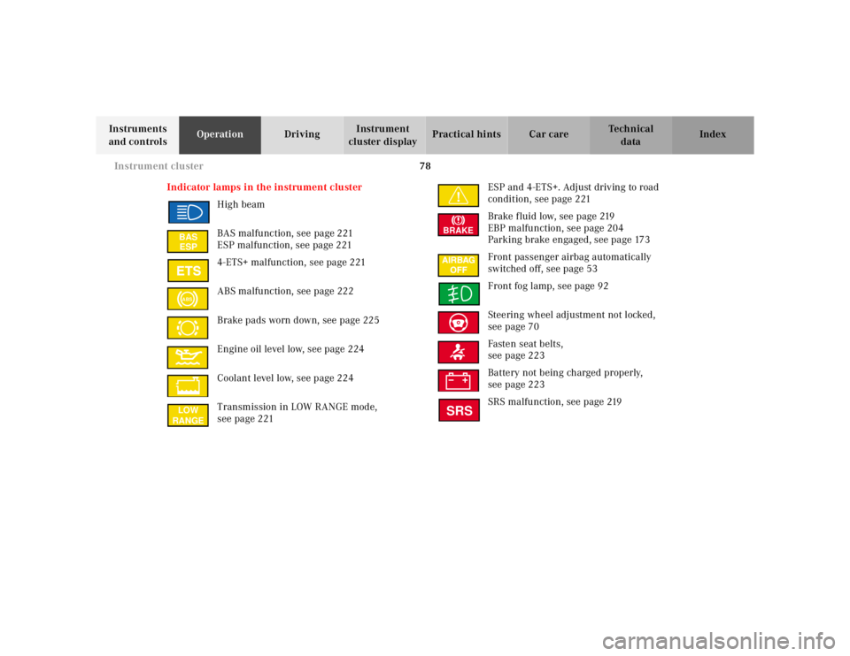
Indicator lamps in the instrument cluster
High beam
BAS malfunction, see page 221
ESP malfunction, see page 221
4-ETS+ malfunction, see page 221
ABS malfunction, see page 222
Brake pads worn down, see page 225
Engine oil level low, see page 224
Coolant level low, see page 224
Transmission in LOW RANGE mode,
see page 221ESP and 4-ETS+. Adjust driving to road
condition, see page 221
Brake fluid low, see page 219
EBP malfunction, see page 204
Parking brake engaged, see page 173
Front passenger airbag automatically
switched off, see page 53
Front fog lamp, see page 92
Steering wheel adjustment not locked,
see page 70
Fasten seat belts,
see page 223
Battery not being charged properly,
see page 223
SRS malfunction, see page 219
BAS
ESPABSLOW
RANGE
BRAKESRS
Page 138 of 4133
88 Flexible service system
Te ch n ica l
data Instruments
and controlsOperationDrivingInstrument
cluster displayPractical hints Car care Index
Important!
The FSS indicator is not an engine oil level indicator.
See page 89 for engine oil level indicator.
Notes:
When disconnecting vehicle battery for one or more
days at a time, such days will not be counted. Any such
days not counted by the FSS can be added by your
Mercedes-Benz Light Truck Center.
The interval between services is determined by the type
of driving for which the vehicle is used. For example,
driving at extreme speeds, and cold starts combined
with short distance driving in which the engine does not
reach normal operating temperature, reduce the interval
between services.
Following a completed A or B service the Mercedes-
Benz Light Truck Center sets the counter mileage to
10 000 miles (Canada: 15 000 km) and 365 days.
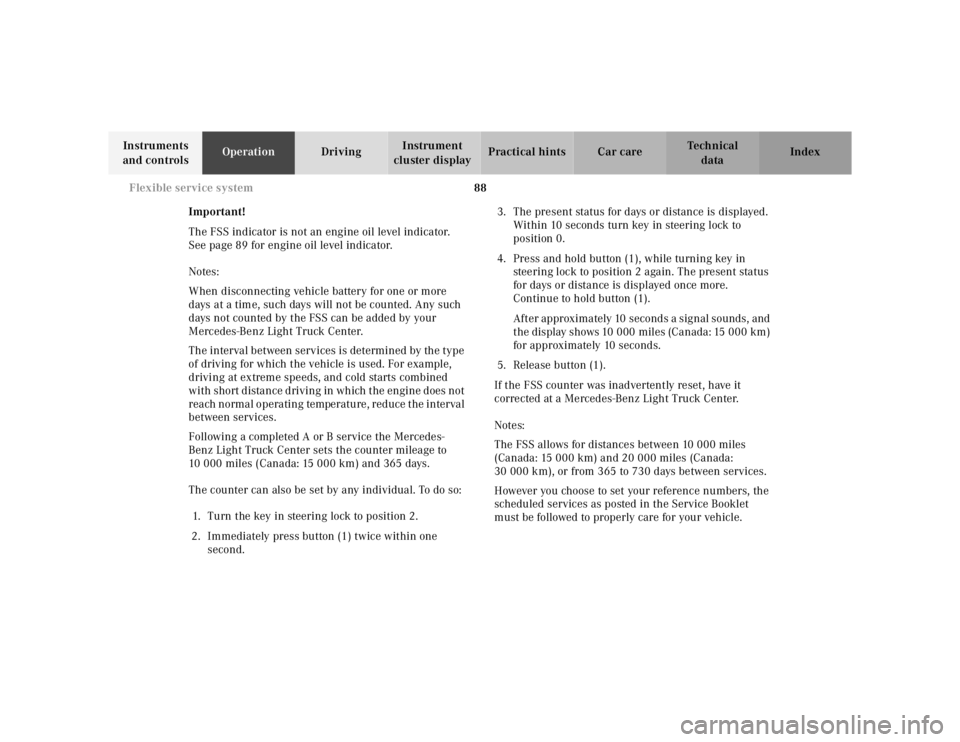
The counter can also be set by any individual. To do so:
1. Turn the key in steering lock to position 2.
2. Immediately press button (1) twice within one
second.3. The present status for days or distance is displayed.
Within 10 seconds turn key in steering lock to
position 0.
4. Press and hold button (1), while turning key in
steering lock to position 2 again. The present status
for days or distance is displayed once more.
Continue to hold button (1).
After approximately 10 seconds a signal sounds, and
the display shows 10 000 miles (Canada: 15 000 km)
for approximately 10 seconds.
5. Release button (1).
If the FSS counter was inadvertently reset, have it
corrected at a Mercedes-Benz Light Truck Center.
Notes:
The FSS allows for distances between 10 000 miles
(Canada: 15 000 km) and 20 000 miles (Canada:
30 000 km), or from 365 to 730 days between services.
However you choose to set your reference numbers, the
scheduled services as posted in the Service Booklet
must be followed to properly care for your vehicle.