1997 MERCEDES-BENZ ML430 center console
[x] Cancel search: center consolePage 5 of 4133

UNDEPLOYED AIR BAG/ETR
After deploying procedures and/or diagnostic testing have confirmed air bag module and/or ETR is
undeployable, contact vehicle manufacturer for proper disposal instructions.
REMOVAL & INSTALLATION
CLOCKSPRING ASSEMBLY
Removal & Installation
1. Before proceeding, see SERVICE PRECAUTIONS . Disable air bag system. See DISABLING &
ACTIVATING AIR BAG SYSTEM .
2. Remove driver air bag module. See DRIVER
-SIDE AIR BAG MODULE . Remove steering wheel bolt.
Using a puller, remove steering wheel. Disconnect lower clockspring connector. Turn 2 fixing screws
(locating on clockspring) counterclockwise until clockspring cannot be rotated. Remove clockspring
mounting screws as necessary. Disconnect all necessary electrical connectors. Remove clockspring
assembly. To install, reverse removal procedure. Activate air bag system. See DISABLING &
ACTIVATING AIR BAG SYSTEM . Perform system operation check to ensure system is functioning
properly. See SYSTEM OPERATION CHECK
.
CONTROL UNIT
Removal & Installation (C Class)
1. Before proceeding, see SERVICE PRECAUTIONS . Disable air bag system. See DISABLING &
ACTIVATING AIR BAG SYSTEM . Remove ignition key. Remove shift lever cover bezel. Lift shift
lever cover enough to disconnect electrical connector. Remove shift lever cover.
2. Remove storage compartment mounting screws from center console. Remove storage compartment.
Remove ashtray. Disconnect electrical connectors as necessary. Disconnect control module electrical
connector. Remove control module mounting bolts. Remove control module.
3. To install, reverse removal procedure. Ensure control module arrow points to front of vehicle. Set
parameters and program new control module with Hand-Held Tester (965 589 00 01 00). Activate air bag
system. Perform system operation check to ensure system is functioning properly. See SYSTEM
OPERATION CHECK .
Removal & Installation (E Class)
1. Before proceeding, see SERVICE PRECAUTIONS . Disable air bag system. See DISABLING &
ACTIVATING AIR BAG SYSTEM . Remove ignition key. Remove gear shift cover panel. Remove
ashtray and ashtray housing at front of console. Remove radio (if necessary).
2. Remove center console right side cover screws and right side cover. Disconnect electrical connector for
control unit. Remove 2 control unit mounting screws. Remove control unit. WARNING:Failure to follow service precautions may result in air bag deployment and
personal injury. See SERVICE PRECAUTIONS
. After component
replacement, check system operation. See SYSTEM OPERATION CHECK
.
1998 Mercedes-Benz ML320
AIR BAG RESTRAINT SYSTEM 1998 AIR BAG RESTRAINT SYSTEMS Mercedes-Benz
me
Saturday, October 02, 2010 3:33:13 PMPage 5 © 2006 Mitchell Repair Information Company, LLC.
Page 6 of 4133

3. To install, reverse removal procedure. Ensure control module arrow points to front of vehicle. Set
parameters and program new control module with Hand-Held Tester (965 589 00 01 00). Activate air bag
system. Perform system operation check to ensure system is functioning properly. See SYSTEM
OPERATION CHECK .
Removal & Installation (S Class)
1. Before proceeding, see SERVICE PRECAUTIONS . Disable air bag system. See DISABLING &
ACTIVATING AIR BAG SYSTEM . Remove ignition key. Remove radio. Remove ashtray. Remove
wooden surround for ashtray. Remove shift lever cover mounting screws. Push shift lever cover toward
rear of vehicle and remove in an upward direction.
2. Remove center console cover screws. Remove center console cover by pulling from bottom in an upward
direction. When removing covers, disconnect electrical connectors as necessary. Disconnect control
module electrical connector. Remove control module.
3. To install, reverse removal procedure. Ensure control module arrow points to front of vehicle. Set
parameters and program new control module with Hand-Held Tester (965 589 00 01 00). Activate air bag
system. Perform system operation check to ensure system is functioning properly. See SYSTEM
OPERATION CHECK .
Removal & Installation (SL Class)
1. Before proceeding, see SERVICE PRECAUTIONS . Disable air bag system. See DISABLING &
ACTIVATING AIR BAG SYSTEM . Remove ignition key. Remove radio. Push up and pull out heater
control panel. Unplug 2 connectors. Remove screw in middle of storage tray.
2. Bend up at top corners and lift out storage tray. Remove screws below storage tray. Lift wood trim panel
at rear, pull down and out of catches. Unplug switch connectors and remove wood trim panel. Unplug
connectors at control unit and remove Torx mounting screws. Remove control unit.
3. To install, reverse removal procedure. Ensure control module arrow points to front of vehicle. Set
parameters and program new control module with Hand-Held Tester (965 589 00 01 00). Activate air bag
system. Perform system operation check to ensure system is functioning properly. See SYSTEM
OPERATION CHECK .
Removal & Installation (CLK 320 & SLK 230)
1. Before proceeding, see SERVICE PRECAUTIONS . Disable air bag system. See DISABLING &
ACTIVATING AIR BAG SYSTEM . Remove ignition key. Remove cover on center console. Remove
cover on shift lever. Remove ash tray housing with storage compartment at front of center console.
Unplug connectors at control unit and remove Torx mounting screws. Remove control unit.
2. To install, reverse removal procedure. Ensure control module arrow points to front of vehicle. Set
parameters and program new control module with Hand-Held Tester (965 589 00 01 00). Activate air bag
system. Perform system operation check to ensure system is functioning properly. See SYSTEM
OPERATION CHECK .
DRIVER-SIDE AIR BAG MODULE
NOTE: Air bag module and steering wheel must be replaced following a collision in
1998 Mercedes-Benz ML320
AIR BAG RESTRAINT SYSTEM 1998 AIR BAG RESTRAINT SYSTEMS Mercedes-Benz
me
Saturday, October 02, 2010 3:33:13 PMPage 6 © 2006 Mitchell Repair Information Company, LLC.
Page 51 of 4133

1 Contents
IntroductionProduct information .......................... 7
Roadside assistance ......................... 10
Where to find it ................................ 14
Reporting Safety Defects ................ 16Instruments and controlsInstruments and controls ............... 18
Center console .............................. 20
Overhead control panel ............... 21OperationVehicle keys ...................................... 24
Start lock-out .................................... 25
General notes on the
central locking system ............... 26
Central locking system ................... 26
Radio frequency
remote control .............................. 26
Unlocking the liftgate .................. 28
Panic button .................................. 28
Mechanical keys ........................... 29Doors ................................................. 30
Central locking switch .................... 32
Automatic central locking .......... 32
Emergency unlocking in case
of accident ................................... 33
Liftgate .............................................. 34
Antitheft alarm system ................... 35
Tow-away alarm and
glass breakage sensor ............... 36
Seats, front ....................................... 37
Manual seats ................................ 39
Power seats ................................... 40
Head restraint ...............................41
Heated seats ..................................... 44
Seat belts and integrated
restraint system .......................... 46
Seat belts .......................................... 46
Seat belt nonusage
warning system ............................ 47
BabySmart
TM airbag
deactivation system ................... 53
Self-test BabySmart
TM
without special child
seat installed ................................ 53Supplemental restraint
system (SRS) ................................ 54
Emergency tensioning
retractor (ETR) ............................. 55
Airbags .............................................. 56
Safety guidelines for the
seat belt, emergency
tensioning retractor
and airbag ..................................... 63
Infant and child
restraint systems .......................... 65
Adjustable steering wheel .............. 70
Inside rear view mirror .................. 71
Antiglare night position .............. 71
Exterior rear view mirrors ............. 73
Exterior rear view mirror,
electrically folding ....................... 75
Instrument cluster ........................... 76
Indicator lamps in the
instrument cluster ...................... 78
Trip computer ................................... 83
Flexible service system (FSS) ........ 87
Engine oil level indicator ................ 89
Exterior lamp switch ....................... 90
Page 67 of 4133
17 Contents - Instruments and controls
Te ch n ica l
data Instruments
and controlsOperation DrivingInstrument
cluster displayPractical hints Car care Index
Instruments and controlsInstruments and controls ............... 18
Center console .............................. 20
Overhead control panel ............... 21
Page 70 of 4133
20 Instruments and controls
Te ch n ica l
data Instruments
and controlsOperation DrivingInstrument
cluster displayPractical hints Car care Index
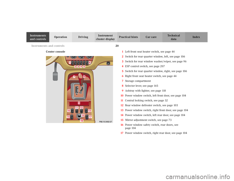
Center console1Left front seat heater switch, see page 44
2Switch for rear quarter window, left, see page 106
3Switch for rear window washer /wiper, see page 96
4ESP control switch, see page 207
5Switch for rear quarter window, right, see page 106
6Right front seat heater switch, see page 44
7Storage compartment
8Selector lever, see page 165
9Ashtray with lighter, see page 118
10Power window switch, left front door, see page 104
11Central locking switch, see page 32
12Rear window defroster switch, see page 103
13Power window switch, right front door, see page 104
14Power window switch, left rear door, see page 104
15Mirror adjustment switch, see page 73
16Power window safety switch, rear doors, see
page 104
17Power window switch, right rear door, see page 104
Page 82 of 4133
32 Central locking system
Te ch n ica l
data Instruments
and controlsOperationDrivingInstrument
cluster displayPractical hints Car care Index
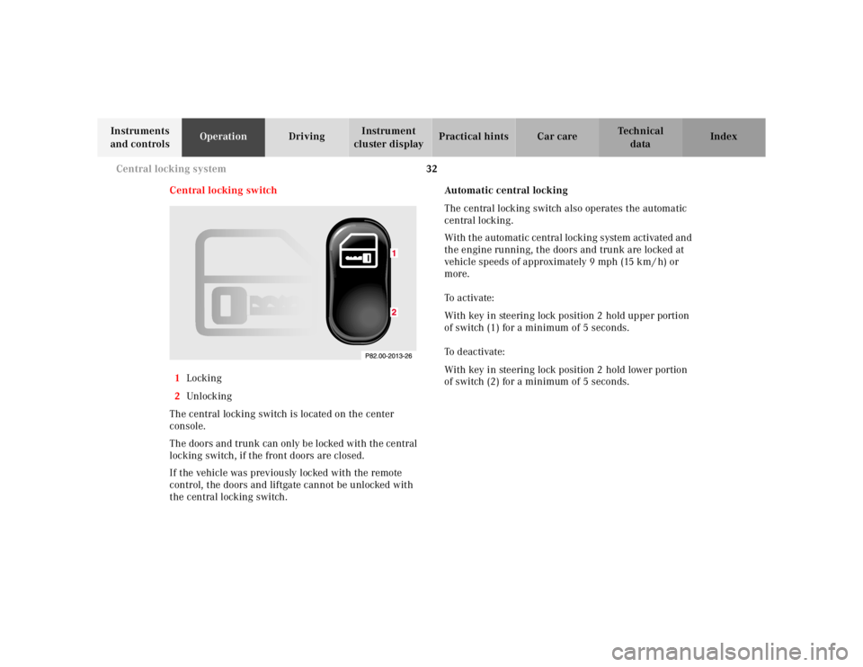
Central locking switch
1Locking
2Unl ock ing
The central locking switch is located on the center
console.
The doors and trunk can only be locked with the central
locking switch, if the front doors are closed.
If the vehicle was previously locked with the remote
control, the doors and liftgate cannot be unlocked with
the central locking switch.Automatic central locking
The central locking switch also operates the automatic
central locking.
With the automatic central locking system activated and
the engine running, the doors and trunk are locked at
vehicle speeds of approximately 9 mph (15 km / h) or
more.
To a c t i v a te :
With key in steering lock position 2 hold upper portion
of switch (1) for a minimum of 5 seconds.
To deactivate:
With key in steering lock position 2 hold lower portion
of switch (2) for a minimum of 5 seconds.
Page 85 of 4133
35 Antitheft alarm system
Te ch n ica l
data Instruments
and controlsOperationDrivingInstrument
cluster displayPractical hints Car care Index Antitheft alarm system
The indicator lamp is located in the center console.
The antitheft alarm is automatically armed or disarmed
with the remote control by locking or unlocking the
vehicle.
The antitheft alarm is armed within approximately
15 seconds after locking the vehicle with the remote
control.
A blinking lamp in the center console indicates that the
alarm is armed.
Notes:
Use of the key in the front door locks does not arm or
disarm the antitheft alarm system.
The alarm sounds when unlocking the driver’s door
with the mechanical key. Cancel alarm by turning key in
steering lock to position 1, or with the remote control by
pressing buttonŒ.
If the vehicle battery voltage falls below 10 volts, the
alarm is automatically canceled and the antitheft alarm
system is disarmed. When the voltage is above this
value again, the antitheft alarm system is armed again.Operation:
Once the alarm system has been armed, the turn signal
lamps will flash rapidly (approximately 3 minutes) and
the horn will sound intermittently (approximately
30 seconds) when someone:
•opens a door,
•opens the liftgate,
•opens the hood,
•breaks a window,
•attempts to raise the vehicle.
The alarm will stay on even if the activating element (a
door, for example) is immediately closed.
If the alarm stays on for more than 20 seconds, an
emergency call is initiated automatically. See Tele Aid
on page 148.
Note:
The alarm system will cycle three times when triggered.
The interior lights are automatically switched on when
the alarm comes on and go out when canceling the
alarm.
Page 94 of 4133
44 Seats
Te ch n ica l
data Instruments
and controlsOperationDrivingInstrument
cluster displayPractical hints Car care Index
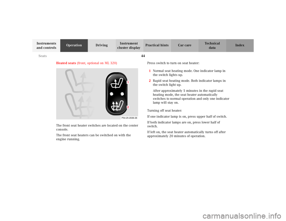
Heated seats (front, optional on ML 320)
The front seat heater switches are located on the center
console.
The front seat heaters can be switched on with the
engine running.Press switch to turn on seat heater:
1Normal seat heating mode. One indicator lamp in
the switch lights up.
2Rapid seat heating mode. Both indicator lamps in
the switch light up.
After approximately 5 minutes in the rapid seat
heating mode, the seat heater automatically
switches to normal operation and only one indicator
lamp will stay on.
Turning off seat heater:
If one indicator lamp is on, press upper half of switch.
If both indicator lamps are on, press lower half of
switch.
If left on, the seat heater automatically turns off after
approximately 20 minutes of operation.
P54.25-2036-26
12