1997 MERCEDES-BENZ ML430 instrument panel
[x] Cancel search: instrument panelPage 12 of 4133
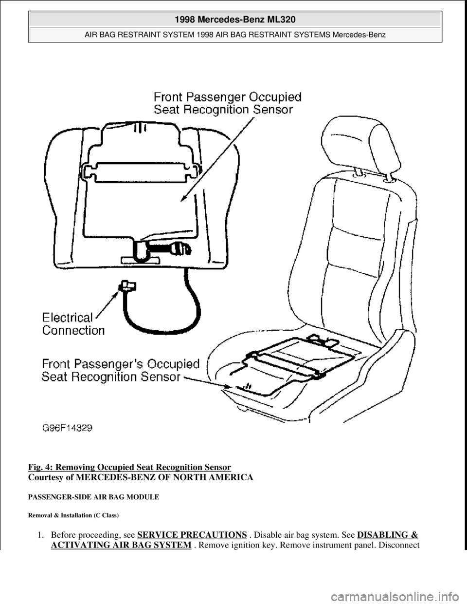
Fig. 4: Removing Occupied Seat Recognition Sensor
Courtesy of MERCEDES-BENZ OF NORTH AMERICA
PASSENGER-SIDE AIR BAG MODULE
Removal & Installation (C Class)
1. Before proceeding, see SERVICE PRECAUTIONS . Disable air bag system. See DISABLING &
ACTIVATING AIR BAG SYSTEM. Remove ignition key. Remove instrument panel. Disconnect
1998 Mercedes-Benz ML320
AIR BAG RESTRAINT SYSTEM 1998 AIR BAG RESTRAINT SYSTEMS Mercedes-Benz
me
Saturday, October 02, 2010 3:33:14 PMPage 12 © 2006 Mitchell Repair Information Company, LLC.
Page 13 of 4133
passenger-side air bag module squib connector. Remove 4 passenger-side air bag module mounting nuts.
2. To install, reverse removal procedure. Ensure passenger-side air bag module squib connector audibly
clicks when connecting connector. Activate air bag system. Perform system operation check to ensure
system is functioning properly. See SYSTEM OPERATION CHECK
.
Removal & Installation (E Class)
1. Before proceeding, see SERVICE PRECAUTIONS . Disable air bag system. See DISABLING &
ACTIVATING AIR BAG SYSTEM . Remove ignition key. Remove 2 central mounting bolts for
passenger-side air bag module. Lift air bag module enough to unplug connector from rear of module.
Place module away from work area, with pad facing upward.
2. If necessary to replace passenger air bag installation frame, remove 4 frame mounting bolts. Remove
installation frame from vehicle.
3. To install air bag module or installation frame, reverse removal procedure. Activate air bag system.
Perform system operation check to ensure system is functioning properly. See SYSTEM OPERATION
CHECK .
Removal & Installation (S Class)
1. Before proceeding, see SERVICE PRECAUTIONS . Disable air bag system. See DISABLING &
ACTIVATING AIR BAG SYSTEM . Remove ignition key. Open glove box door. Remove 4 clips
securing glove box. Remove glove box compartment. When removing compartment, disconnect glove
box light. Remove glove box door lock striker.
2. Disconnect passenger-side air bag module squib connector. Remove 4 passenger-side air bag module
mounting nuts. Remove passenger-side air bag module through glove box opening. Place module away
from work area with pad facing up.
3. To install, reverse removal procedure. Ensure module squib connector audibly clicks when connecting
connector. Activate air bag system. Perform system operation check to ensure system is functioning
properly. See SYSTEM OPERATION CHECK
.
Removal & Installation (SL Class)
1. Before proceeding, see SERVICE PRECAUTIONS . Disable air bag system. See DISABLING &
ACTIVATING AIR BAG SYSTEM . Remove ignition key. Remove cover below instrument panel.
Remove one bolt in installation slot of center air outlet, and one bolt below right air outlet.
2. Remove air bag panel (3 Phillips screws and 2 hex bolts). Unplug connector at squib of passenger-side air
bag unit. Remove mounting bolts. Pull off and take air bag out of panel opening.
3. To install air bag module, reverse removal procedure. Activate air bag system. Perform system operation
check to ensure system is functioning properly. See SYSTEM OPERATION CHECK
.
Removal & Installation (CLK 320)
1. Before proceeding, see SERVICE PRECAUTIONS . Disable air bag system. See DISABLING &
ACTIVATING AIR BAG SYSTEM . Remove ignition key. Remove instrument panel. Disconnect
passenger-side air bag module connector. Remove 4 screws and passenger-side air bag module.
2. To install air ba
g module, reverse removal procedure. Activate air bag system. Perform system operation
1998 Mercedes-Benz ML320
AIR BAG RESTRAINT SYSTEM 1998 AIR BAG RESTRAINT SYSTEMS Mercedes-Benz
me
Saturday, October 02, 2010 3:33:14 PMPage 13 © 2006 Mitchell Repair Information Company, LLC.
Page 14 of 4133
check to ensure system is functioning properly. See SYSTEM OPERATION CHECK .
Removal & Installation (SLK 230)
1. Before proceeding, see SERVICE PRECAUTIONS . Disable air bag system. See DISABLING &
ACTIVATING AIR BAG SYSTEM . Remove ignition key. Remove top section of instrument panel.
Fold vapor barrier toward front to reveal 2 screws. Disconnect passenger-side air bag module connector.
Remove 4 screws and passenger-side air bag module.
2. To install air bag module, reverse removal procedure. Activate air bag system. Perform system operation
check to ensure system is functioning properly. See SYSTEM OPERATION CHECK
.
SYSTEM OPERATION CHECK
SRS warning light indicates air bag and Emergency Tensioning Retractor (ETR) system readiness. Turn
ignition on. SRS warning light will light, and then go out after approximately 4 seconds indicating system is
functioning properly. If SRS warning light does not light, lights up while driving or lights all the time, there is a
system fault. Repair malfunctioning system. See DIAGNOSIS & TESTING
.
SERVICE PRECAUTIONS
Observe following precautions when working with air bag systems:
When working around steering column components and before any repairs are performed, disable air bag
system. See DISABLING & ACTIVATING AIR BAG SYSTEM
.
Before straightening any damage to body, or before performing electrical arc-welding, disable air bag
system. See DISABLING & ACTIVATING AIR BAG SYSTEM
.
Always wear safety glasses and gloves when handling a deployed air bag module. Air bag module may
contain sodium hydroxide deposits which are irritating to the skin.
DO NOT repair any portion of SRS wiring harness.
Always handle air bag module with trim cover away from your body. Always place air bag module on
workbench with trim cover up, away from loose objects.
DO NOT expose any SRS component to temperatures in excess of 212°F (100°C).
DO NOT expose any SRS component to cleaning agents such as solvents, gasoline, lye, etc.
DO NOT connect Hand-Held Tester (6511 0001 99) to Data Link Connector (DLC) with ignition on.
Damage to HHT may result.
DO NOT connect HHT (6511 0001 99) to vehicle if a battery charger is connected to vehicle battery.
Damage to HHT may result.
DISABLING & ACTIVATING AIR BAG SYSTEM DISABLING SYSTEM
Before proceeding, follow air bag service precautions. See SERVICE PRECAUTIONS
. Turn ignition off.
Disconnect and shield negative battery cable. Remove passenger foot mat. Remove passenger footrest.
Disconnect SRS system connector (X29/9) located at passenger footwell area. See Fig. 5
. System is now
disabled.
1998 Mercedes-Benz ML320
AIR BAG RESTRAINT SYSTEM 1998 AIR BAG RESTRAINT SYSTEMS Mercedes-Benz
me
Saturday, October 02, 2010 3:33:14 PMPage 14 © 2006 Mitchell Repair Information Company, LLC.
Page 51 of 4133

1 Contents
IntroductionProduct information .......................... 7
Roadside assistance ......................... 10
Where to find it ................................ 14
Reporting Safety Defects ................ 16Instruments and controlsInstruments and controls ............... 18
Center console .............................. 20
Overhead control panel ............... 21OperationVehicle keys ...................................... 24
Start lock-out .................................... 25
General notes on the
central locking system ............... 26
Central locking system ................... 26
Radio frequency
remote control .............................. 26
Unlocking the liftgate .................. 28
Panic button .................................. 28
Mechanical keys ........................... 29Doors ................................................. 30
Central locking switch .................... 32
Automatic central locking .......... 32
Emergency unlocking in case
of accident ................................... 33
Liftgate .............................................. 34
Antitheft alarm system ................... 35
Tow-away alarm and
glass breakage sensor ............... 36
Seats, front ....................................... 37
Manual seats ................................ 39
Power seats ................................... 40
Head restraint ...............................41
Heated seats ..................................... 44
Seat belts and integrated
restraint system .......................... 46
Seat belts .......................................... 46
Seat belt nonusage
warning system ............................ 47
BabySmart
TM airbag
deactivation system ................... 53
Self-test BabySmart
TM
without special child
seat installed ................................ 53Supplemental restraint
system (SRS) ................................ 54
Emergency tensioning
retractor (ETR) ............................. 55
Airbags .............................................. 56
Safety guidelines for the
seat belt, emergency
tensioning retractor
and airbag ..................................... 63
Infant and child
restraint systems .......................... 65
Adjustable steering wheel .............. 70
Inside rear view mirror .................. 71
Antiglare night position .............. 71
Exterior rear view mirrors ............. 73
Exterior rear view mirror,
electrically folding ....................... 75
Instrument cluster ........................... 76
Indicator lamps in the
instrument cluster ...................... 78
Trip computer ................................... 83
Flexible service system (FSS) ........ 87
Engine oil level indicator ................ 89
Exterior lamp switch ....................... 90
Page 67 of 4133
17 Contents - Instruments and controls
Te ch n ica l
data Instruments
and controlsOperation DrivingInstrument
cluster displayPractical hints Car care Index
Instruments and controlsInstruments and controls ............... 18
Center console .............................. 20
Overhead control panel ............... 21
Page 71 of 4133
21 Instruments and controls
Te ch n ica l
data Instruments
and controlsOperation DrivingInstrument
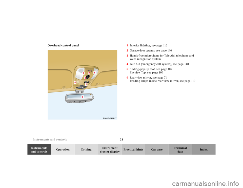
cluster displayPractical hints Car care Index Overhead control panel1Interior lighting, see page 110
2Garage door opener, see page 140
3Hands-free microphone for Tele Aid, telephone and
voice recognition system
4Tele Aid (emergency call system), see page 148
5Sliding /pop-up roof, see page 107
Skyview Top, see page 109
6Rear view mirror, see page 71
Reading lamps inside rear view mirror, see page 110
1
2
3
4
5
6
1
Page 101 of 4133
51 Restraint systems
Te ch n ica l
data Instruments
and controlsOperationDrivingInstrument
cluster displayPractical hints Car care Index
• Never wear the shoulder belt under your arm,
against your neck or off your shoulder. In a
crash, your body would move too far forward.
That would increase the chance of head and
neck injuries. The belt would also apply too
much force to the ribs or abdomen, which
could severely injure internal organs such as
your liver or spleen.• Never wear belts over rigid or breakable
objects in or on your clothing, such as
eyeglasses, pens, keys etc., as these might
cause injuries.• Position the lap belt as low as possible on your
hips and not across the abdomen. If the belt is
positioned across your abdomen, it could cause
serious injuries in a crash.
• Each seat belt should never be used for more
than one person at a time. Do not fasten a seat
belt around a person and another person or
other objects.• Belts should not be worn twisted. In a crash,
you wouldn’t have the full width of the belt to
manage impact forces. The twisted belt against
your body could cause injuries.• Pregnant women should also use a lap-
shoulder belt. The lap belt portion should be
positioned as low as possible on the hips to
avoid any possible pressure on the abdomen.• Never place your feet on the instrument panel
or on the seat. Always keep both feet on the
floor in front of the seat.
Page 113 of 4133
63 Restraint systems
Te ch n ica l
data Instruments
and controlsOperationDrivingInstrument
cluster displayPractical hints Car care Index Safety guidelines for the seat belt,
emergency tensioning retractor and airbag
Wa r n i n g !
• Damaged seat belts or belts that were highly
stressed in an accident must be replaced and
their anchoring points must also be checked.
Use only belts installed or supplied by an
authorized Mercedes-Benz Light Truck Center.• Do not pass belts over sharp edges.• Do not make any modification that could
change the effectiveness of the belts.• Airbags and ETR’s are designed to function on
a one-time-only basis. An airbag or emergency
tensioning retractor (ETR) that was activated
must be replaced.
• An airbag system component within the
steering wheel gets hot after the airbag has
inflated. Do not touch.• Improper work on the system, including
incorrect installation and removal, can lead to
possible injury through an unintended
activation of the “SRS”.• No modifications of any kind may be made to
any components or wiring of the “SRS”. This
includes changing or removing any component
or part of the “SRS”, the installation of
additional trim material, badges etc. over the
steering wheel hub, front passenger airbag
cover, or front door trim panels, and
installation of additional electrical / electronic
equipment on or near “SRS” components and
wiring. Keep area between airbags and
occupants free of objects (e.g. packages,
purses, umbrellas, etc.).