1997 MERCEDES-BENZ ML430 instrument panel
[x] Cancel search: instrument panelPage 307 of 4133
257 Towing
Te ch n ica l
data Instruments
and controlsOperation DrivingInstrument
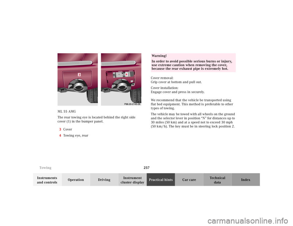
cluster displayPractical hintsCar care Index ML 55 AMG
The rear towing eye is located behind the right side
cover (1) in the bumper panel.
3Cover
4Towing eye, rearCover removal:
Grip cover at bottom and pull out.
Cover installation:
Engage cover and press in securely.
We recommend that the vehicle be transported using
flat bed equipment. This method is preferable to other
types of towing.
The vehicle may be towed with all wheels on the ground
and the selector lever in position “N” for distances up to
30 miles (50 km) and at a speed not to exceed 30 mph
(50 k m / h). The key mu st be in stee ring lo ck p o sitio n 2.
Wa r n i n g !
In order to avoid possible serious burns or injury,
use extreme caution when removing the cover,
because the rear exhaust pipe is extremely hot.
Page 316 of 4133
266 Exterior lamps
Te ch n ica l
data Instruments
and controlsOperation DrivingInstrument
cluster displayPractical hintsCar care Index
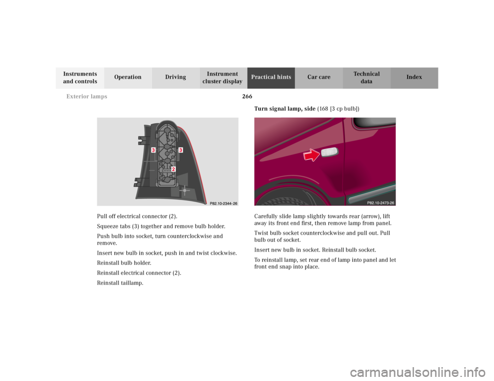
Pull off electrical connector (2).
Squeeze tabs (3) together and remove bulb holder.
Push bulb into socket, turn counterclockwise and
remove.
Insert new bulb in socket, push in and twist clockwise.
Reinstall bulb holder.
Reinstall electrical connector (2).
Reinstall taillamp.Turn signal lamp, side (168 [3 cp bulb])
Carefully slide lamp slightly towards rear (arrow), lift
away its front end first, then remove lamp from panel.
Twist bulb socket counterclockwise and pull out. Pull
bulb out of socket.
Insert new bulb in socket. Reinstall bulb socket.
To reinstall lamp, set rear end of lamp into panel and let
front end snap into place.
Page 324 of 4133
274 Manual release for fuel filler flap
Te ch n ica l
data Instruments
and controlsOperation DrivingInstrument
cluster displayPractical hintsCar care Index
Important!
After manually operating the Skyview Top, a timing
synchronization is needed for future electrical operation
o f the Sk yv iew To p. To do s o, tur n key i n stee ri n g lock to
position 2. Now push and hold switch until the Skyview
Top is fully closed. Continue to hold switch for
additional 15 seconds.Manual release for fuel filler flap
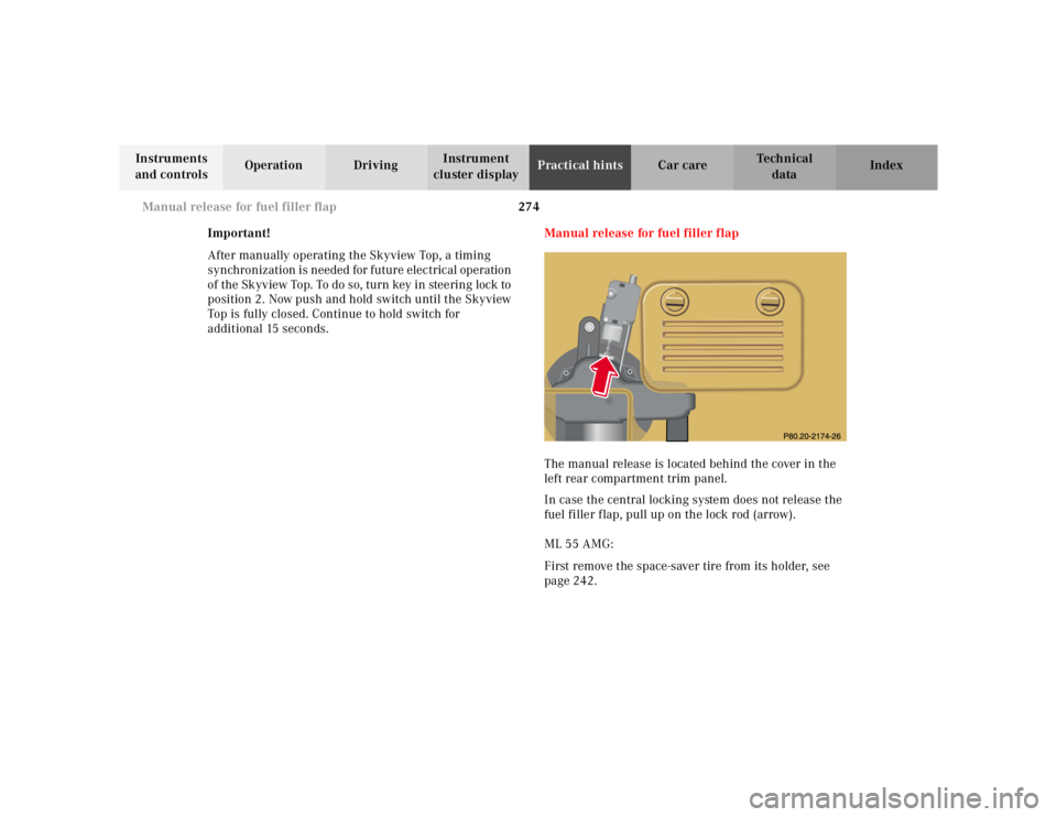
The manual release is located behind the cover in the
left rear compartment trim panel.
In case the central locking system does not release the
fuel filler flap, pull up on the lock rod (arrow).
ML 55 AMG:
First remove the space-saver tire from its holder, see
page 242.
Page 352 of 4133
302 Index
Te ch n ica l
data Instruments
and controlsOperation DrivingInstrument
cluster displayPractical hints Car careIndex
Clock, adjusting ............................................................... 80
Compartment under front passenger seat ..................116
Consumer information ..................................................298
Control and operation of radio transmitters ............. 146
Coolant level
Adding ........................................................................235
Checking ....................................................................234
Low engine coolant level warning ..........................224
Coolant temperature gauge ............................................ 81
Coolants ...........................................................................296
Anticorrosion/antifreeze quantity .........................296
Low engine coolant level warning ..........................224
Cover blind, cargo area ................................................. 137
Cruise control ................................................................. 196
Cup holder
Instrument panel .......................................................116
Rear center console ...................................................117
DDaytime running lamps .................................................. 91
Deep water
Driving instructions ................................................. 181
Defroster, rear window .................................................. 103
Display illumination ........................................................ 80Doors .................................................................................. 30
Drinking and driving ..................................................... 174
Drive sensibly - save fuel .............................................. 174
Driving instructions ...................................................... 174
Driving off ....................................................................... 176
EEBP (Electronic brake proportioning) ........................ 204
Electrical outlet ............................................................. 230
Electronic brake proportioning (EBP) ........................ 204
Electronic stability program (ESP) ............................. 205
Control switch .......................................................... 207
Malfunction indicator lamp .....................................221
Synchronizing .......................................................... 206
Warning lamp ............................................................221
Electronic traction system (4-ETS+) ........................... 203
LOW RANGE – 4-ETS ............................................... 204
Malfunction indicator lamp .....................................221
Emergency call
See Tele Aid ...............................................................148
Emergency operation of Skyview Top ....................... 273
Emergency tensioning retractor (ETR) .........................55
Emergency unlocking in case of accident ...................33
Emission control ............................................................ 161
Page 357 of 4133
307 Index
Te ch n ica l
data Instruments
and controlsOperation DrivingInstrument
cluster displayPractical hints Car careIndex
OObtaining replacement keys .......................................... 25
Odometer/Trip odometer ................................................ 80
Off-Road driving ............................................................. 183
On-board diagnostic system ......................................... 218
Operator’s manual ............................................................. 8
Outside temperature indicator ...................................... 82
Overhead control panel ................................................... 21PPanic button ...................................................................... 28
Parking .............................................................................176
Parking brake ....................... 118, 173, 175, 176, 219, 245
Partition net .................................................................... 133
Poly-V-belt
Layout .........................................................................286
Power assistance ............................................................ 175
Power seats, front ............................................................ 40
Memory ........................................................................ 42
Memory recalling ....................................................... 42
Memory storing ........................................................... 42Power windows ...............................................................104
Blocking of rear door windows ............................... 105
Express opening of front door windows ................ 105
Problems with your vehicle ............................................ 15
Product information .......................................................... 7
RRadio transmitters ......................................................... 146
Rain sensor
See windshield wiper/washer switch ......................95
Rear quarter windows ...................................................106
Rear seat bench ..............................................................120
Easy entry/exit feature ............................................123
Head restraints ..........................................................124
Rear seat head restraints ..............................................124
Adjusting ....................................................................125
Removal ......................................................................125
Rear view mirrors
Exterior ......................................................................... 73
Inside ............................................................................ 71
Rear window defroster .................................................. 103
Rear window wiper/washer ...........................................96
Page 377 of 4133
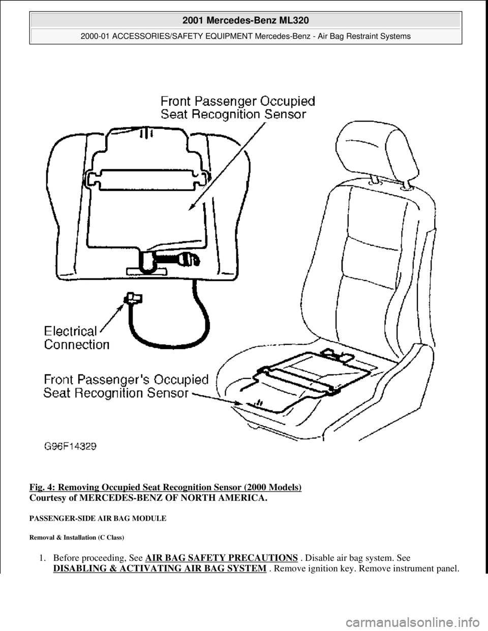
Fig. 4: Removing Occupied Seat Recognition Sensor (2000 Models)
Courtesy of MERCEDES-BENZ OF NORTH AMERICA.
PASSENGER-SIDE AIR BAG MODULE
Removal & Installation (C Class)
1. Before proceeding, See AIR BAG SAFETY PRECAUTIONS . Disable air bag system. See
DISABLING & ACTIVATI NG AIR BAG SYSTEM
. Remove ignition key. Remove instrument panel.
2001 Mercedes-Benz ML320
2000-01 ACCESSORIES/SAFETY EQUIPMENT Merc edes-Benz - Air Bag Restraint Systems
me
Saturday, October 02, 2010 3:44:45 PMPage 13 © 2006 Mitchell Repair Information Company, LLC.
Page 378 of 4133
Disconnect passenger-side air bag module squib connector. Remove 4 passenger-side air bag module
mounting nuts.
2. To install, reverse removal proc edure. Ensure passenger-side air bag module squib connector audibly
clicks when connecting connector. Activate air bag system. Perform system operation check to ensure
system is functioning properly. See SYSTEM OPERATION CHECK
.
Removal & Installation (E Class)
1. Before proceeding, See AIR BAG SAFETY PRECAUTIONS . Disable air bag system. See
DISABLING & ACTIVATI NG AIR BAG SYSTEM
. Remove ignition key. Remove 2 central
mounting bolts for passenger-side air bag module. Li ft air bag module enough to unplug connector from
rear of module. Place module away fr om work area, with pad facing upward.
2. If necessary to replace passenger air bag instal lation frame, remove 4 frame mounting bolts. Remove
installation frame from vehicle.
3. To install air bag module or inst allation frame, reverse removal proc edure. Activate air bag system.
Perform system operation check to ensu re system is functioning properly. See SYSTEM OPERATION
CHECK .
Removal & Installation (S Class)
1. Before proceeding, See AIR BAG SAFETY PRECAUTIONS . Disable air bag system. See
DISABLING & ACTIVATI NG AIR BAG SYSTEM
. Remove ignition key. Open glove box door.
Remove 4 clips securing glove bo x. Remove glove box compartment. When removing compartment,
disconnect glove box light. Remove glove box door lock striker.
2. Disconnect passenger-side air bag module squib c onnector. Remove 4 passenger-side air bag module
mounting nuts. Remove passenger- side air bag module through glove box opening. Place module away
from work area with pad facing up.
3. To install, reverse removal proc edure. Ensure module squib connector audibly clicks when connecting
connector. Activate air bag system. Perform system operation check to ensure system is functioning
properly. See SYSTEM OPERATION CHECK
.
Removal & Installation (SL Class)
1. Before proceeding, See AIR BAG SAFETY PRECAUTIONS . Disable air bag system. See
DISABLING & ACTIVATI NG AIR BAG SYSTEM
. Remove ignition key. Remove cover below
instrument panel. Remove one bolt in installation slot of center air outlet, and one bolt below right air
outlet.
2. Remove air bag panel (3 Phillips screws and 2 hex bol ts). Unplug connector at squib of passenger-side air
bag unit. Remove mounting bo lts. Pull off and take air bag out of panel opening.
3. To install air bag module, reverse removal procedur e. Activate air bag system. Perform system operation
check to ensure system is functioning properly. See SYSTEM OPERATION CHECK
.
Removal & Installation (CLK 320)
1. Before proceeding, See AIR BAG SAFETY PRECAUTIONS . Disable air bag system. See
DISABLING & ACTIVATI NG AIR BAG SYSTEM
. Remove ignition key. Remove instrument panel.
Disconnect passen
ger-side air bag module connector. Remove 4 screws and passenger-side air bag
2001 Mercedes-Benz ML320
2000-01 ACCESSORIES/SAFETY EQUIPMENT Merc edes-Benz - Air Bag Restraint Systems
me
Saturday, October 02, 2010 3:44:45 PMPage 14 © 2006 Mitchell Repair Information Company, LLC.
Page 379 of 4133
module.
2. To install air bag module, reverse removal procedur e. Activate air bag system. Perform system operation
check to ensure system is functioning properly. See SYSTEM OPERATION CHECK
.
Removal & Installation (SLK 320)
1. Before proceeding, See AIR BAG SAFETY PRECAUTIONS . Disable air bag system. See
DISABLING & ACTIVATI NG AIR BAG SYSTEM
. Remove ignition key. Remove top section of
instrument panel. Fold vapor barrier toward front to reveal 2 screws. Disconnect passenger-side air bag
module connector. Remove 4 screws and passenger-side air bag module.
2. To install air bag module, reverse removal procedur e. Activate air bag system. Perform system operation
check to ensure system is functioning properly. See SYSTEM OPERATION CHECK
.
DIAGNOSTICS
Before proceeding, see AIR BAG SAFETY PRECAUTIONS
. The SRS control module is capable of
diagnosing air bag system components and ETR components. If a fault is detected by the SRS control module
or system is malfunctioning, SRS warning light will do one or more of the following:
SRS warning light goes out after 2 minutes. System fault is noted, however occupant protection is not
affected. See RETRIEVING FAULT CODES
.
SRS warning light illuminates cont inuously. System is faulty which may result in a non deployment or
false deployment. See RETRIEVING FAULT CODES
.
SRS warning light blinks continuous ly. Control module has been replaced without setting control module
parameters.
RETRIEVING FAULT CODES
1. Check vehicle fuses. Replace any blown fuses as nece ssary. Ensure vehicle battery voltage is 11 volts or
more. Ensure SRS warning light functions. Turn i gnition off. Connect Hand-Held Tester (HHT) (965 589
00 01) to Data Link Connector (DLC).
2. DLC is located in right rear corner of engine comp artment. It may be necessary to use Adapter (965 589
00 40 or 965 589 00 50) to connect HHT to DLC. Afte r HHT displays module number and version, press
return key to start diagnosis. Us ing HHT, follow HHT prompts to re trieve SRS fault codes. For SRS
control modules beginning with number 000, fault c ode 1 is valid. For SRS control modules beginning
with number 001, fault code 2 is valid. See Fig. 6
.
3. HHT will display a 3 digit fault code, and may display additional graphic information. This additional
graphic information will help in diagnosis of fault code. See Fig. 5
. During diagnosis HHT will display 4
different graphic displays info rming technician if a test passes or fail s, or if seat belt buckle is latched or
NOTE: After component replacement, perf
orm a system operation check to ensure
proper system operation. S ee SYSTEM OPERATION CHECK
.
NOTE: Fault codes may only be retrieved us ing Hand-Held Tester (965 589 00 01) and
Adapter (965 589 00 40 or 965 589 00 50).
2001 Mercedes-Benz ML320
2000-01 ACCESSORIES/SAFETY EQUIPMENT Merc edes-Benz - Air Bag Restraint Systems
me
Saturday, October 02, 2010 3:44:45 PMPage 15 © 2006 Mitchell Repair Information Company, LLC.