1997 MERCEDES-BENZ ML430 instrument panel
[x] Cancel search: instrument panelPage 769 of 4133
302
Index
Te ch n ica l
data
Instruments
and controls Operation Driving
Instrument
cluster display Practical hints Car care
Index
Clock, adjusting ............................................................... 80
Compartment under front passenger seat ..................116
Consumer information ..................................................298
Control and operation of radio transmitters ............. 146
Coolant level Adding ........................................................................235
Checking ....................................................................234
Low engine coolant level warning ..........................224
Coolant temperature gauge ............................................ 81
Coolants ...........................................................................296
Anticorrosion/antifreeze quantity .........................296
Low engine coolant level warning ..........................224
Cover blind, cargo area ................................................. 137
Cruise control ................................................................. 196
Cup holder Instrument panel .......................................................116
Rear center console ...................................................117
DDaytime running lamps .................................................. 91
Deep water Driving instructions ................................................. 181
Defroster, rear window .................................................. 103
Display illumination ........................................................ 80 Doors .................................................................................. 30
Drinking and driving ..................................................... 174
Drive sensibly - save fuel .............................................. 174
Driving instructions ...................................................... 174
Driving off ....................................................................... 176
EEBP (Electronic brake proportioning) ........................ 204
Electrical outlet ............................................................. 230
Electronic brake proportioning (EBP) ........................ 204
Electronic stability program (ESP) ............................. 205 Control switch .......................................................... 207
Malfunction indicator lamp .....................................221
Synchronizing .......................................................... 206
Warning lamp ............................................................221
Electronic traction system (4-ETS+) ........................... 203 LOW RANGE – 4-ETS ............................................... 204
Malfunction indicator lamp .....................................221
Emergency call See Tele Aid ...............................................................148
Emergency operation of Skyview Top ....................... 273
Emergency tensioning retractor (ETR) .........................55
Emergency unlocking in case of accident ...................33
Emission control ............................................................ 161
Page 774 of 4133
307
Index
Te ch n ica l
data
Instruments
and controls Operation Driving
Instrument
cluster display Practical hints Car care
Index
OObtaining replacement keys .......................................... 25
Odometer/Trip odometer ................................................ 80
Off-Road driving ............................................................. 183
On-board diagnostic system ......................................... 218
Operator’s manual ............................................................. 8
Outside temperature indicator ...................................... 82
Overhead control panel ................................................... 21PPanic button ...................................................................... 28
Parking .............................................................................176
Parking brake ....................... 118, 173, 175, 176, 219, 245
Partition net .................................................................... 133
Poly-V-belt Layout .........................................................................286
Power assistance ............................................................ 175
Power seats, front ............................................................ 40 Memory ........................................................................ 42
Memory recalling ....................................................... 42
Memory storing ........................................................... 42 Power windows ...............................................................104
Blocking of rear door windows ............................... 105
Express opening of front door windows ................ 105
Problems with your vehicle ............................................ 15
Product information .......................................................... 7
RRadio transmitters ......................................................... 146
Rain sensor See windshield wiper/washer switch ......................95
Rear quarter windows ...................................................106
Rear seat bench ..............................................................120 Easy entry/exit feature ............................................123
Head restraints ..........................................................124
Rear seat head restraints ..............................................124 Adjusting ....................................................................125
Removal ......................................................................125
Rear view mirrors Exterior ......................................................................... 73
Inside ............................................................................ 71
Rear window defroster .................................................. 103
Rear window wiper/washer ...........................................96
Page 782 of 4133
2003 ACCESSORIES/SAFETY EQUIPMENT
Mercedes-Benz - Air Bag Restraint Systems
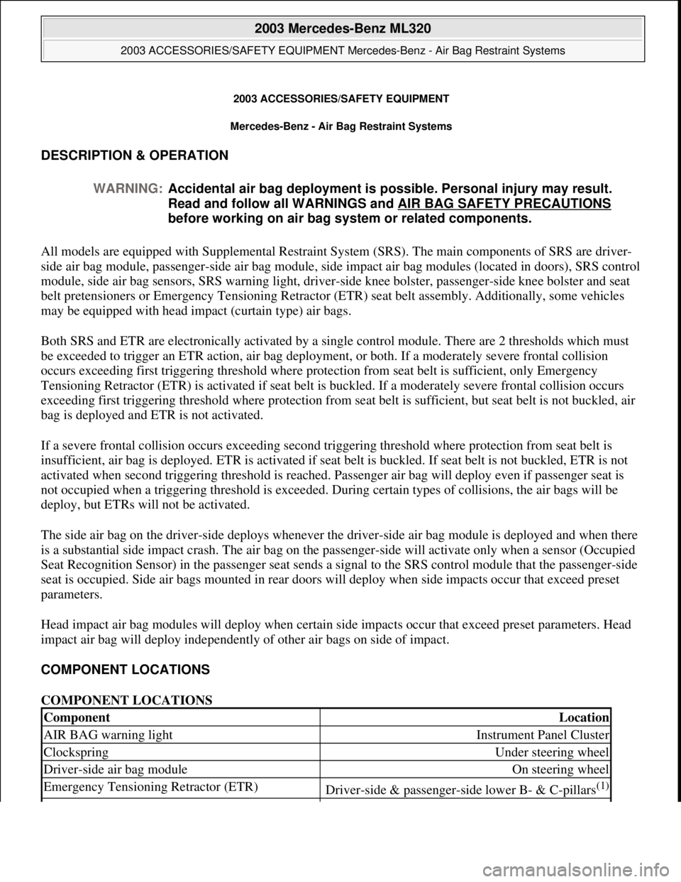
DESCRIPTION & OPERATION
All models are equipped with Supplemental Restraint System (SRS). The main components of SRS are driver-
side air bag module, passenger-side air bag module, side impact air bag modules (located in doors), SRS control
module, side air bag sensors, SRS warning light, driver-side knee bolster, passenger-side knee bolster and seat
belt pretensioners or Emergency Tensioning Retractor (ETR) seat belt assembly. Additionally, some vehicles
may be equipped with head impact (curtain type) air bags.
Both SRS and ETR are electronically activated by a single control module. There are 2 thresholds which must
be exceeded to trigger an ETR action, air bag deployment, or both. If a moderately severe frontal collision
occurs exceeding first triggering threshold where protection from seat belt is sufficient, only Emergency
Tensioning Retractor (ETR) is activated if seat belt is buckled. If a moderately severe frontal collision occurs
exceeding first triggering threshold where protection from seat belt is sufficient, but seat belt is not buckled, air
bag is deployed and ETR is not activated.
If a severe frontal collision occurs exceeding second triggering threshold where protection from seat belt is
insufficient, air bag is deployed. ETR is activated if seat belt is buckled. If seat belt is not buckled, ETR is not
activated when second triggering threshold is reached. Passenger air bag will deploy even if passenger seat is
not occupied when a triggering threshold is exceeded. During certain types of collisions, the air bags will be
deploy, but ETRs will not be activated.
The side air bag on the driver-side deploys whenever the driver-side air bag module is deployed and when there
is a substantial side impact crash. The air bag on the passenger-side will activate only when a sensor (Occupied
Seat Recognition Sensor) in the passenger seat sends a signal to the SRS control module that the passenger-side
seat is occupied. Side air bags mounted in rear doors will deploy when side impacts occur that exceed preset
parameters.
Head impact air bag modules will deploy when certain side impacts occur that exceed preset parameters. Head
impact air bag will deploy independently of other air bags on side of impact.
COMPONENT LOCATIONS
COMPONENT LOCATIONS WARNING:Accidental air bag deployment is possible. Personal injury may result.
Read and follow all WARNINGS and AIR BAG SAFETY PRECAUTIONS
before working on air bag system or related components.
ComponentLocation
AIR BAG warning lightInstrument Panel Cluster
ClockspringUnder steering wheel
Driver-side air bag moduleOn steering wheel
Emergency Tensioning Retractor (ETR)Driver-side & passenger-side lower B- & C-pillars(1)
2003 Mercedes-Benz ML320
2003 ACCESSORIES/SAFETY EQUIPMENT Mercedes-Benz - Air Bag Restraint Systems
2003 Mercedes-Benz ML320
2003 ACCESSORIES/SAFETY EQUIPMENT Mercedes-Benz - Air Bag Restraint Systems
me
Saturday, October 02, 2010 3:32:07 PMPage 1 © 2006 Mitchell Repair Information Company, LLC.
me
Saturday, October 02, 2010 3:32:10 PMPage 1 © 2006 Mitchell Repair Information Company, LLC.
Page 783 of 4133
SERVICING
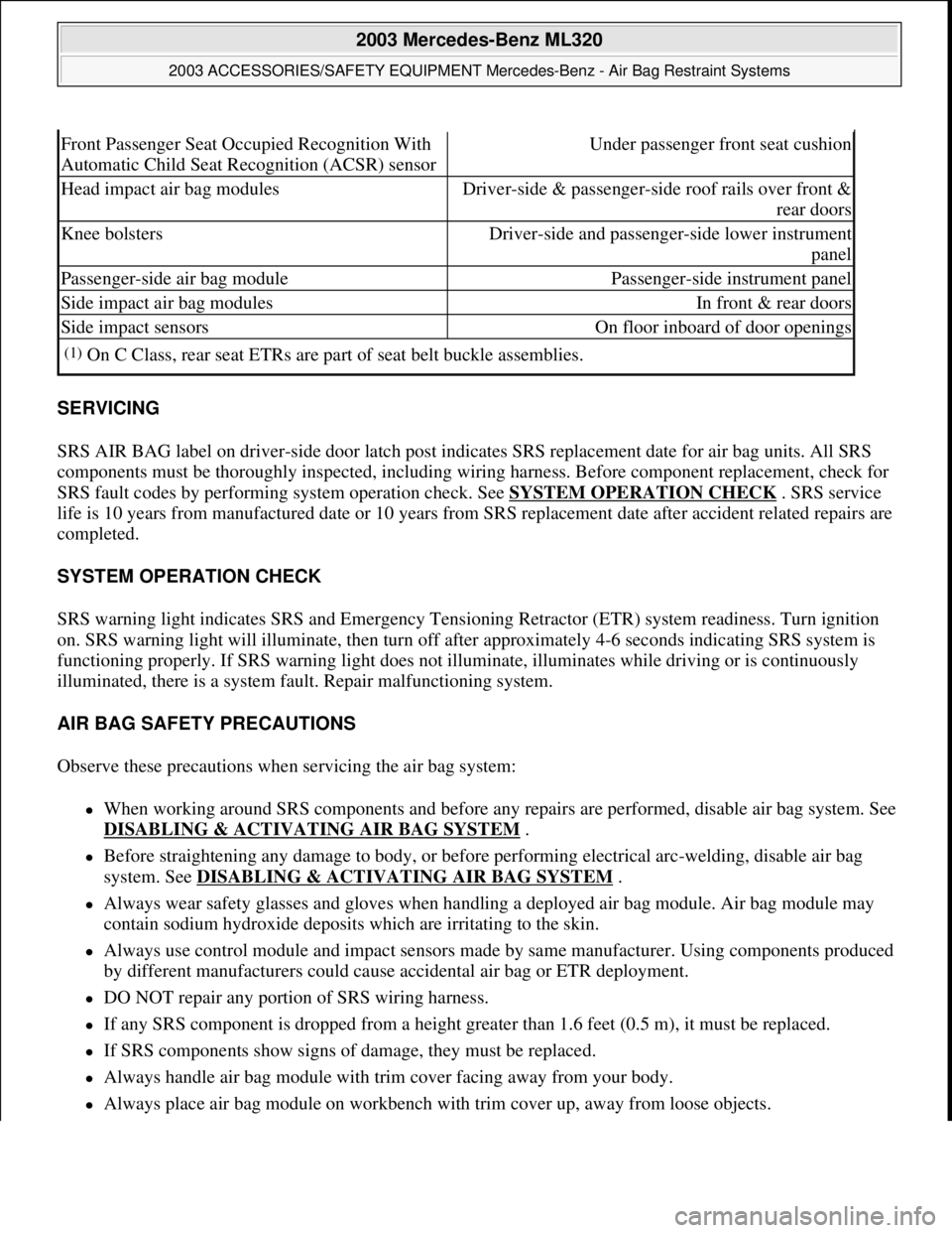
SRS AIR BAG label on driver-side door latch post indicates SRS replacement date for air bag units. All SRS
components must be thoroughly inspected, including wiring harness. Before component replacement, check for
SRS fault codes by performing system operation check. See SYSTEM OPERATION CHECK
. SRS service
life is 10 years from manufactured date or 10 years from SRS replacement date after accident related repairs are
completed.
SYSTEM OPERATION CHECK
SRS warning light indicates SRS and Emergency Tensioning Retractor (ETR) system readiness. Turn ignition
on. SRS warning light will illuminate, then turn off after approximately 4-6 seconds indicating SRS system is
functioning properly. If SRS warning light does not illuminate, illuminates while driving or is continuously
illuminated, there is a system fault. Repair malfunctioning system.
AIR BAG SAFETY PRECAUTIONS
Observe these precautions when servicing the air bag system:
When working around SRS components and before any repairs are performed, disable air bag system. See
DISABLING & ACTIVATING AIR BAG SYSTEM
.
Before straightening any damage to body, or before performing electrical arc-welding, disable air bag
system. See DISABLING & ACTIVATING AIR BAG SYSTEM
.
Always wear safety glasses and gloves when handling a deployed air bag module. Air bag module may
contain sodium hydroxide deposits which are irritating to the skin.
Always use control module and impact sensors made by same manufacturer. Using components produced
by different manufacturers could cause accidental air bag or ETR deployment.
DO NOT repair any portion of SRS wiring harness.
If any SRS component is dropped from a height greater than 1.6 feet (0.5 m), it must be replaced.
If SRS components show signs of damage, they must be replaced.
Always handle air bag module with trim cover facing away from your body.
Always place air bag module on workbench with trim cover up, away from loose objects.
Front Passenger Seat Occupied Recognition With
Automatic Child Seat Recognition (ACSR) sensorUnder passenger front seat cushion
Head impact air bag modulesDriver-side & passenger-side roof rails over front &
rear doors
Knee bolstersDriver-side and passenger-side lower instrument
panel
Passenger-side air bag modulePassenger-side instrument panel
Side impact air bag modulesIn front & rear doors
Side impact sensorsOn floor inboard of door openings
(1)On C Class, rear seat ETRs are part of seat belt buckle assemblies.
2003 Mercedes-Benz ML320
2003 ACCESSORIES/SAFETY EQUIPMENT Mercedes-Benz - Air Bag Restraint Systems
me
Saturday, October 02, 2010 3:32:07 PMPage 2 © 2006 Mitchell Repair Information Company, LLC.
Page 786 of 4133
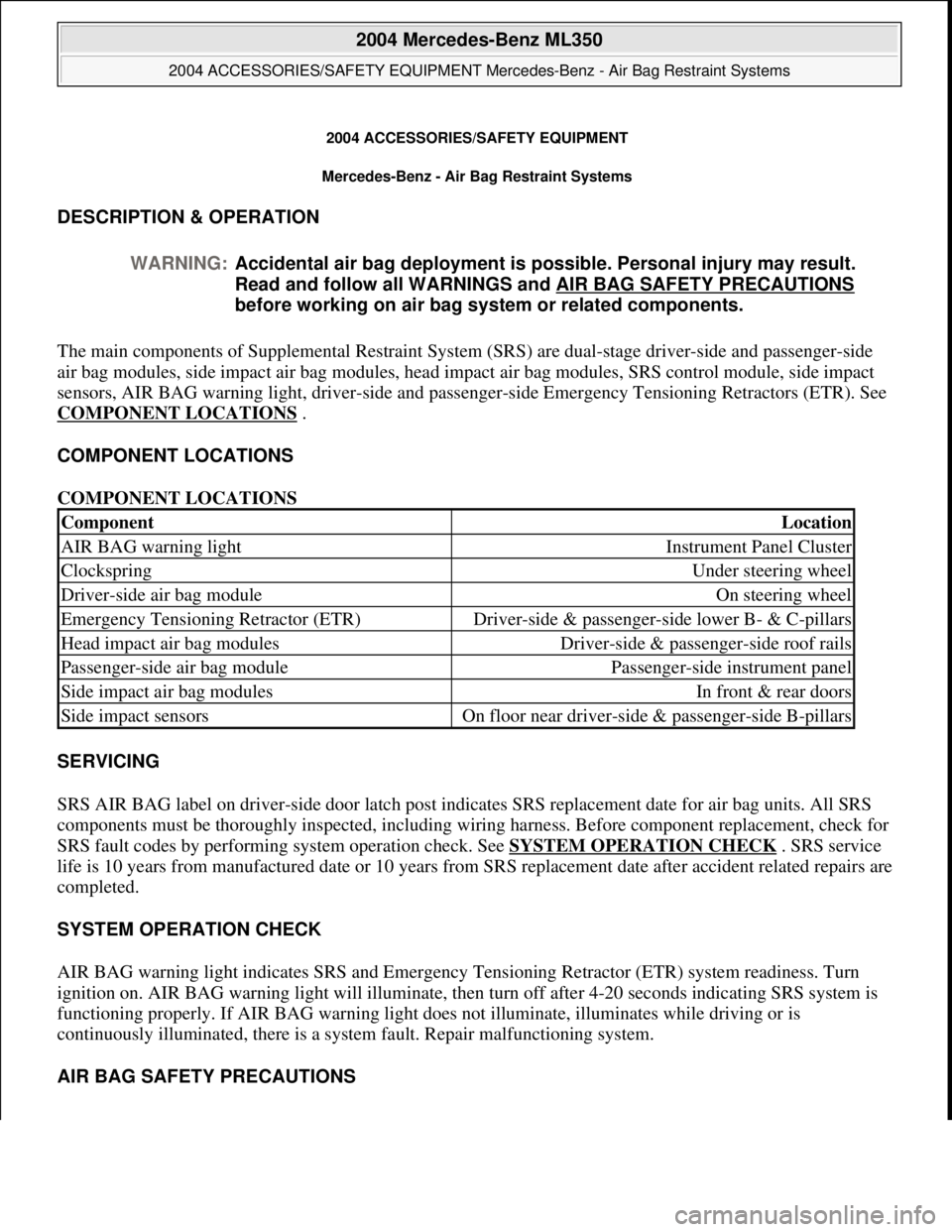
2004 ACCESSORIES/SAF ETY EQUIPMENT
Mercedes-Benz - Air Bag Restraint Systems
DESCRIPTION & OPERATION
The main components of Supplemental Restraint System (SRS) are dual-stage driver-side and passenger-side
air bag modules, side impact air bag modules, head impact air bag modules , SRS control module, side impact
sensors, AIR BAG warning light, driv er-side and passenger-side Emergency Tensioning Retractors (ETR). See
COMPONENT LOCATIONS
.
COMPONENT LOCATIONS
COMPONENT LOCATIONS
SERVICING
SRS AIR BAG label on driver-side door latch post indicates SRS replacement date for air bag units. All SRS
components must be thoroughly inspected, including wiring harness. Before component replacement, check for
SRS fault codes by performing system operation check. See SYSTEM OPERATION CHECK
. SRS service
life is 10 years from manufactured da te or 10 years from SRS replacement date after accident related repairs are
completed.
SYSTEM OPERATION CHECK
AIR BAG warning light indicates SRS and Emergency Te nsioning Retractor (ETR) system readiness. Turn
ignition on. AIR BAG warning light will illuminate, then turn off after 4-20 seconds indicating SRS system is
functioning properly. If AIR BAG warn ing light does not illuminate, illuminates while driving or is
continuously illuminated, ther e is a system fault. Repair malfunctioning system.
AIR BAG SAFETY PRECAUTIONS
WARNING:
Accidental air bag deployment is pos sible. Personal injury may result.
Read and follow all WARNINGS and AIR BAG SAFETY PRECAUTIONS
before working on ai r bag system or related components.
ComponentLocation
AIR BAG warning lightInstrument Panel Cluster
ClockspringUnder steering wheel
Driver-side air bag moduleOn steering wheel
Emergency Tensioning Retractor (ETR)Driver-side & passenger-si de lower B- & C-pillars
Head impact air bag modulesDriver-side & passenger-side roof rails
Passenger-side air bag modulePassenger-side instrument panel
Side impact air bag modulesIn front & rear doors
Side impact sensorsOn floor near driver-side & passenger-side B-pillars
2004 Mercedes-Benz ML350
2004 ACCESSORIES/SAFETY EQUIPMENT Merce des-Benz - Air Bag Restraint Systems
2004 Mercedes-Benz ML350
2004 ACCESSORIES/SAFETY EQUIPMENT Mercedes-Benz - Air Bag Restraint Systems
me
Saturday, October 02, 2010 3:40:40 PMPage 1 © 2006 Mitchell Repair Information Company, LLC.
me
Saturday, October 02, 2010 3:40:43 PMPage 1 © 2006 Mitchell Repair Information Company, LLC.
Page 793 of 4133
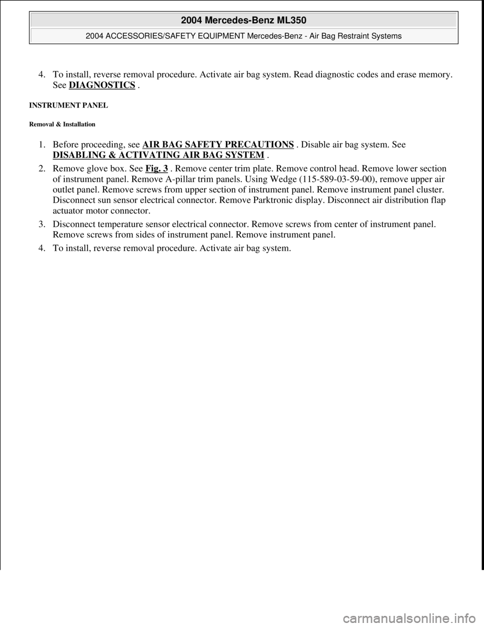
4. To install, reverse removal proce dure. Activate air bag system. Read diagnostic codes and erase memory.
See DIAGNOSTICS
.
INSTRUMENT PANEL
Removal & Installation
1. Before proceeding, see AIR BAG SAFETY PRECAUTIONS . Disable air bag system. See
DISABLING & ACTIVATI NG AIR BAG SYSTEM
.
2. Remove glove box. See Fig. 3
. Remove center trim plate. Remove control head. Remove lower section
of instrument panel. Remove A-pillar trim pa nels. Using Wedge (115-589-03-59-00), remove upper air
outlet panel. Remove screws from upper section of instrument panel. Remove instrument panel cluster.
Disconnect sun sensor electrical c onnector. Remove Parktronic display. Disconnect air distribution flap
actuator motor connector.
3. Disconnect temperature sensor el ectrical connector. Remove screws from center of instrument panel.
Remove screws from sides of instrument panel. Remove instrument panel.
4. To install, reverse remova l procedure. Activate air ba
g system.
2004 Mercedes-Benz ML350
2004 ACCESSORIES/SAFETY EQUIPMENT Merce des-Benz - Air Bag Restraint Systems
me
Saturday, October 02, 2010 3:40:40 PMPage 8 © 2006 Mitchell Repair Information Company, LLC.
Page 794 of 4133
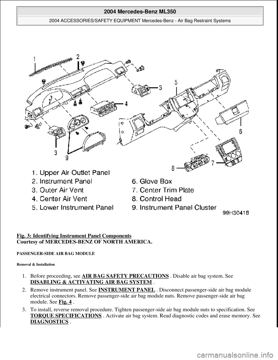
Fig. 3: Identifying Instrument Panel Components
Courtesy of MERCEDES-BENZ OF NORTH AMERICA.
PASSENGER-SIDE AIR BAG MODULE
Removal & Installation
1. Before proceeding, see AIR BAG SAFETY PRECAUTIONS . Disable air bag system. See
DISABLING & ACTIVATI NG AIR BAG SYSTEM
.
2. Remove instrument panel. See INSTRUMENT PANEL
. Disconnect passenger-side air bag module
electrical connectors. Remove pass enger-side air bag module nuts. Remove passenger-side air bag
module. See Fig. 4
.
3. To install, reverse removal proc edure. Tighten passenger-side air bag module nuts to specification. See
TORQUE SPECIFICATIONS
. Activate air bag system. Read di agnostic codes and erase memory. See
DIAGNOSTICS
.
2004 Mercedes-Benz ML350
2004 ACCESSORIES/SAFETY EQUIPMENT Merce des-Benz - Air Bag Restraint Systems
me
Saturday, October 02, 2010 3:40:40 PMPage 9 © 2006 Mitchell Repair Information Company, LLC.
Page 807 of 4133
Contents
Introduction.......................................... 9
Product information ................................ 9
Operator’s Manual ............................... 10
Service and warranty information .. 10
Important notice for California
retail buyers and lessees
of Mercedes-Benz automobiles ...... 11
Maintenance .................................. 12
Roadside Assistance ...................... 12
Change of address or ownership.... 13
Operating your vehicle outside
the USA or Canada......................... 13
Where to find it .................................... 15
Symbols ............................................... 16
Operating safety .................................. 17
Proper use of the vehicle ............... 17
Problems with your vehicle .................. 18
Reporting safety defects...................... 19
Reporting safety defects ................ 19
At a glance.......................................... 21
Cockpit ................................................. 22
Instrument cluster ................................ 24
Center console ..................................... 27
Upper part ...................................... 27
Lower part ...................................... 28
Overhead control panel ........................ 29Getting started................................... 31
Unlocking ............................................. 32
Remote control with folding key ..... 32
Adjusting .............................................. 34
Seats............................................... 34
Steering wheel ................................ 39
Mirrors ............................................ 40Driving .................................................. 42
Fastening the seat belts ................. 42
Starting the engine ......................... 46
Switching on headlamps ................. 48
Turn signals .................................... 49
Windshield wipers ........................... 49
Rear window wiper ......................... 51
Problems while driving.................... 51
Parking and locking .............................. 53
Parking brake ................................. 53
Switching off headlamps................. 54
Turning off engine ........................... 54